EP1387207A2 - Optisches Projektionssystem, Projektionsbildanzeigevorrichtung, und Bildanzeigesystem - Google Patents
Optisches Projektionssystem, Projektionsbildanzeigevorrichtung, und Bildanzeigesystem Download PDFInfo
- Publication number
- EP1387207A2 EP1387207A2 EP03254754A EP03254754A EP1387207A2 EP 1387207 A2 EP1387207 A2 EP 1387207A2 EP 03254754 A EP03254754 A EP 03254754A EP 03254754 A EP03254754 A EP 03254754A EP 1387207 A2 EP1387207 A2 EP 1387207A2
- Authority
- EP
- European Patent Office
- Prior art keywords
- optical system
- projection
- reflective
- image
- optical
- Prior art date
- Legal status (The legal status is an assumption and is not a legal conclusion. Google has not performed a legal analysis and makes no representation as to the accuracy of the status listed.)
- Withdrawn
Links
Images



Classifications
-
- G—PHYSICS
- G02—OPTICS
- G02B—OPTICAL ELEMENTS, SYSTEMS OR APPARATUS
- G02B17/00—Systems with reflecting surfaces, with or without refracting elements
- G02B17/08—Catadioptric systems
- G02B17/0852—Catadioptric systems having a field corrector only
-
- G—PHYSICS
- G02—OPTICS
- G02B—OPTICAL ELEMENTS, SYSTEMS OR APPARATUS
- G02B17/00—Systems with reflecting surfaces, with or without refracting elements
- G02B17/08—Catadioptric systems
- G02B17/0836—Catadioptric systems using more than three curved mirrors
- G02B17/0848—Catadioptric systems using more than three curved mirrors off-axis or unobscured systems in which not all of the mirrors share a common axis of rotational symmetry, e.g. at least one of the mirrors is warped, tilted or decentered with respect to the other elements
-
- G—PHYSICS
- G03—PHOTOGRAPHY; CINEMATOGRAPHY; ANALOGOUS TECHNIQUES USING WAVES OTHER THAN OPTICAL WAVES; ELECTROGRAPHY; HOLOGRAPHY
- G03B—APPARATUS OR ARRANGEMENTS FOR TAKING PHOTOGRAPHS OR FOR PROJECTING OR VIEWING THEM; APPARATUS OR ARRANGEMENTS EMPLOYING ANALOGOUS TECHNIQUES USING WAVES OTHER THAN OPTICAL WAVES; ACCESSORIES THEREFOR
- G03B21/00—Projectors or projection-type viewers; Accessories therefor
- G03B21/10—Projectors with built-in or built-on screen
-
- G—PHYSICS
- G03—PHOTOGRAPHY; CINEMATOGRAPHY; ANALOGOUS TECHNIQUES USING WAVES OTHER THAN OPTICAL WAVES; ELECTROGRAPHY; HOLOGRAPHY
- G03B—APPARATUS OR ARRANGEMENTS FOR TAKING PHOTOGRAPHS OR FOR PROJECTING OR VIEWING THEM; APPARATUS OR ARRANGEMENTS EMPLOYING ANALOGOUS TECHNIQUES USING WAVES OTHER THAN OPTICAL WAVES; ACCESSORIES THEREFOR
- G03B21/00—Projectors or projection-type viewers; Accessories therefor
- G03B21/14—Details
- G03B21/28—Reflectors in projection beam
Definitions
- the present invention relates generally to a projection optical system for use in a projection type image display apparatus such as a projector, and more particularly, to a projection optical system for projecting an image onto a projection surface in a direction which is oblique to the projection surface.
- Some of projection optical systems for use in such projectors allow projection in a direction which is oblique to the screen in order to reduce the distance between the screen and the projector.
- Japanese Patent Application Laid-Open No. H05(1993)-100312 has proposed a projection optical system which enlargingly projects an image produced on the basis of an original image formed on an image forming element onto a screen.
- a wide-angle lens with a wide field angle is used, and the image forming element and the screen are disposed with a displacement from the optical axis of the projection optical system to use marginal portions of the field angle for the projection, thereby projecting the image in a direction oblique to the screen.
- Japanese Patent Application Laid-Open No. H05(1993)-080418 has proposed a projection optical system which forms an intermediate image of luminous flux from an image forming element by a first projection optical system and enlargingly projects the intermediate image onto a screen by a second projection optical system.
- the optical axes of the first and second projection optical systems are appropriately inclined to project the image onto the screen in a direction oblique to the screen.
- Japanese Patent No. 2786796 has disclosed a projection optical system in which light incident on an ellipsoidal mirror at a first focal point is guided to a second focal point which is disposed to match a focal point of a parabolic mirror, and the light guided to the focal point of the inclined parabolic mirror is projected as collimated light onto a screen in a direction oblique to the screen.
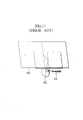
- Japanese Patent Application Laid-Open No. 2001-264627 has proposed an oblique projection optical system which includes an image forming optical system 602 with a positive optical power and a curved mirror 603 with a negative optical power and provides a positive optical power in total to project an image onto a screen 605, as shown in Fig. 11.
- the projection optical system proposed in Domestic re-publication of PCT international publication for patent application WO97/01787 uses one concave mirror and one or two convex mirrors to form a coaxial optical system and projects an image in an oblique direction by partially using reflective surfaces of the concave mirror and the convex mirror(s).
- the coaxial optical system is used, however, it is difficult to correct aberration and provide a brighter reflective optical system, that is, have a smaller F number.
- the projection optical system proposed in Japanese Patent Application Laid-Open No. 2001-264627 does not form an intermediate image since the overall system has the positive optical power.
- eliminating distortion of an image without affecting performance of image formation requires the curved mirror with the negative optical power disposed close to the screen, but the curved mirror has a large size.
- the present invention provides a projection optical system which projects luminous flux from an original image onto a projection surface which is oblique to a central principal ray which is a principal ray of luminous flux traveling from the center of the original image to the center of a projected image.
- the projection optical system comprises a refractive optical system which includes a plurality of refractive optical elements through which the luminous flux from the original image passes through, and a reflective optical system which includes a plurality of reflective surfaces each having an optical power and guides the luminous flux emerging from the refractive optical system to the projection surface.
- a light ray emerging from the center of an original image displayed on an image forming element to the center of a projected image on a projection surface through the center of a pupil is referred to as a central principal ray (or a reference axis ray).
- the center cannot be defined in azimuthal directions with no symmetry of the image forming element and the pupil (the aperture stop), the barycenter of each of them is defined as the center.
- the present invention is also applicable when a path (a reference axis) of the central principal ray can be considered as the substantial center of each of them in Embodiments of the present invention.
- Embodiments of the present invention section views and numerical data of optical systems are shown.
- Each of the rotationally asymmetric surfaces in Embodiments has a plane-symmetric shape which has a yz plane as a plane of symmetry since the above expression has only even-numbered order terms for x and no odd-numbered order terms.
- Embodiments of the present invention employ the expression with a sixth order for representing the surface
- the present invention is applicable without being limited to any particular order for defining the surface shape.
- the shape of each surface may be represented by another expression such as the Zernike polynomial.
- an image forming element modulates illumination light to form an image (an original image), and a projection optical system enlarges luminous flux emerging from the image forming element and guides the luminous flux to form an image on a projection surface or an image surface.
- the projection is performed obliquely such that the central principal ray of the luminous flux guided to the projection surface is projected at an angle not perpendicular to the projection surface.
- the oblique projection of the projection optical system onto the projection surface causes less interference of a projection of the projection optical system to the projection surface as compared with perpendicular projection when viewed from a direction of the normal line to the projection surface.
- An angle between the central principal ray and the normal line to the projection surface that is, an oblique projection angle may be increased to eliminate the interference, and a plane folding mirror may be used to fold the optical path.
- This can realize a thin rear projector (a rear projection type image display apparatus), for example.
- the projection optical system To enhance performance of image formation, on the projection surface, of light from the original image on the image forming element at a large oblique projection angle, the projection optical system must allow ready correction of an astigmatic difference, curvature of field, distortion, and trapezoidal distortion which occur significantly due to decentering of the image surface.
- the relationship between the focal length at the azimuth in the decentering direction and the focal length at the azimuth orthogonal thereto is such that the focal length at the azimuth orthogonal to the decentering direction is equal to the value determined by multiplying the focal length at the azimuth in the decentering direction by the cosine of the oblique projection angle if the image surface is decentered to realize the projection optical system of the oblique projection type.
- the focal length depends on the azimuth of the central principal ray. This is described, for example, in Japanese Patent Application Laid-Open No.2001-255462.
- azimuth dependence of the focal length of the overall optical system must be provided by having azimuth dependence of the optical power of each optical surface within the projection optical system for the oblique projection.
- each of Embodiments of the present invention employs a projection optical system formed of a refractive optical system and a reflective optical system.
- the refractive optical system mainly corrects spherical aberration and comatic aberration, and reflective surfaces having optical powers of the reflective optical system correct an astigmatic difference, curvature of field, distortion, and trapezoidal distortion which need considerable correction due to the large oblique projection angle.
- the ratio of a focal length f_a of the reflective optical system to a focal length f of the overall projection optical system desirably satisfies the following:
- the ratio is smaller, light rays are incident on the reflective optical system at a smaller height.
- the ratio is equal to or lower than the lower limit in the expression (2), the height of the light rays is extremely small to require stronger azimuth dependence of radius of curvature in order to make correction of azimuth dependence of the focal length necessary for the oblique projection of the central principal ray onto the projection surface. Consequently, other types of aberration are difficult to correct.
- the astigmatic difference and curvature of field are corrected by a rotationally asymmetric surface such as a free-form surface, an anamorphic surface, or a toric surface which allows flexible design of the optical power for each azimuth.
- a rotationally symmetric surface may be decentered.
- the optical power of the refractive optical system is excessively reduced, luminous flux is incident on the reflective surface at a light ray height which remains large.
- the number of reflective surfaces in the reflective optical system must be increased to correct the astigmatic difference, distortion, and trapezoidal distortion.
- luminous flux of the off-axis light ray is diverged to cause an increase in the size of the reflective optical system.
- the optical path can be folded before incidence on the inclined projection surface.
- the overall optical path can be folded to reduce the thickness.
- the projection optical system has an intermediate image forming position at an optical surface close to the image surface
- the height of the light ray at optical surfaces closer to the image surface becomes smaller to facilitate correction of distortion with optical power distribution which has less influence on the astigmatic difference.
- the distortion can be corrected even when the angle (the oblique projection angle) between the central principal ray and the projection surface is large.
- the optical power is asymmetric in the azimuthal direction of 0 and 90 degrees in an optical surface near the intermediate image forming position, a flexible relationship is established between the object height and the focal length, thereby allowing correction of distortion even at a large oblique projection angle.
- An optical surface closer to or closest to the intermediate image forming position can be formed as a reflective surface to correct large distortion with a small number of optical surfaces since the reflective surface can provide a larger optical power than the refractive surface.
- the concave and convex shapes of the intermediate image forming surface caused by the curvature of field are matched with the concave and convex shapes of an optical surfaces near the intermediate image forming surface, so that the distortion can be corrected favorably.
- each of optical surfaces having optical powers disposed immediately before and after the intermediate image forming surface may be shaped in the azimuthal directions of 0 and 90 degrees such that the surface has a concave shape toward each azimuthal direction when the refractive optical system has negative curvature of field and the surface has a convex shape toward each azimuthal direction when the refractive optical system has positive curvature of field.
- Table 6 shows values of the expression (2), vertical and horizontal dimensions of image forming elements (for example, reflective type liquid crystal display panels), effective F numbers, vertical and horizontal dimensions of screens (projection surfaces), focal lengths f_a of refractive optical systems, focal lengths f of projection optical systems in longitudinal directions of the screens, and oblique projection angles ⁇ of central principal rays projected onto the screens, in Numerical Examples 1 to 5.
- image forming elements for example, reflective type liquid crystal display panels
- effective F numbers for example, vertical and horizontal dimensions of screens (projection surfaces), focal lengths f_a of refractive optical systems, focal lengths f of projection optical systems in longitudinal directions of the screens, and oblique projection angles ⁇ of central principal rays projected onto the screens, in Numerical Examples 1 to 5.
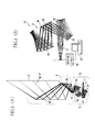
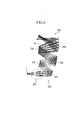
- Fig. 1(A) shows the structure of all optical systems of a rear projector (a projection type image display apparatus) which is Embodiment 1 of the present invention. While Embodiment 1 employs a reflective type liquid crystal panel (element) as an image forming element, the present invention is applicable to an apparatus using a transmissive type image forming element. In addition to the liquid crystal element, other image forming elements can be used as the image forming element, such as a self-light-emission element (for example, an organic or inorganic electroluminescence element) and a micromirror device.
- a self-light-emission element for example, an organic or inorganic electroluminescence element
- a micromirror device for example, a micromirror device.
- Fig. 1(B) shows a projection optical system 10 which is a main part of all the optical systems.
- reference numeral 1 shows a reflective type liquid crystal panel (the image forming element) which is connected to a driving circuit 20 as shown in Fig. 1(B).
- the driving circuit 20 receives image information from an image information supply apparatus 25 such as a personal computer, a VCR, a television, a DVD player, a camera (a video camera, a digital camera or the like), a cellular phone, and a radio wave receiver (wired or wireless). An image display system is formed in this manner.
- the driving circuit 20 drives the reflective type liquid crystal panel 1 such that an original image corresponding to the input image information is displayed on the reflective type liquid crystal panel 1. This structure is also used in other Embodiments later described, although not shown.
- the reflective type liquid crystal panel 1 Upon incidence of illumination light from an illumination system, not shown, the reflective type liquid crystal panel 1 modulates the light into image light and reflects the light. The image light modulated and reflected by the reflective type liquid crystal panel 1 is first incident on a refractive optical system 2 of the projection optical system 10.
- the refractive optical system 2 is disposed at a position closer to the reflective type liquid crystal panel 1 serving as an object surface in all the optical systems, where the refractive optical system 2 receives the light from the reflective type liquid crystal panel 1 at a large height of light rays, and mainly corrects spherical aberration and comatic aberration.
- the refractive optical system 2 is formed of lenses which are rotationally symmetric with respect to the central principal ray from the reflective type liquid crystal panel 1.
- the refractive optical system 2 of Embodiment 1 is formed of five spherical lenses. The number of the spherical lenses, however, is not limited thereto in the refractive optical system of the present invention.
- a rotationally asymmetric spherical surface may also be used in the refractive optical system to improve correction of the spherical aberration.
- Reference numeral 3 shows a reflective optical system of the projection optical system 10, on which the image light emerging from the refractive optical system 2 is incident.
- the reflective optical system 3 is disposed closer to a screen 5 serving as an image surface relative to the refractive optical system 2 in all the optical systems and mainly corrects distortion and trapezoidal distortion.
- the reflective optical system 3 is formed of four reflective surfaces (a first to a fourth reflective surface 31 to 34) or mirrors to sequentially reflect the image light from the refractive optical system 2.
- the number of the reflective surfaces is not limited thereto in the reflective optical system of the present invention.
- the reflective optical system 3 is preferably formed of three or more reflective surfaces since an astigmatic difference can be favorably corrected, satisfactory performance of image formation is achieved, and the distortion and trapezoidal distortion can be favorably corrected, even the central principal ray is projected onto the screen 5 at a large oblique projection angle of 42.5 degrees as in Embodiment 1.
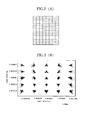
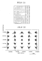
- Fig. 2(B) illustrates performance of image formation on the screen of the projection optical system 10 of Embodiment 1.
- the horizontal axis and vertical axis represent object heights in a horizontal direction and a vertical direction.
- Fig. 2(A) shows distortion of an image on the screen. It can be seen from Fig. 2(A) that the projection optical system 10 of Embodiment 1 can excellently correct the distortion and trapezoidal distortion.
- each of the first reflective surface 31 and the second reflective surface 32 is disposed at a relatively high position of light rays and corrects azimuth dependence of a focal length and astigmatism.
- rotationally asymmetric surfaces used as the first reflective surface 31 and the second reflective surface 32 can provide varying optical powers depending on the azimuth to enhance the effect of correction.
- Each of the third reflective surface 33 and the fourth reflective surface 34 is disposed at a position close to an intermediate image forming surface M shown in Fig. 1(B) where they receive light rays at a relatively small height, and corrects the distortion.
- the intermediate image forming surface M is provided within the reflective optical system 3 to dispose the reflective surfaces near the intermediate image forming surface M, thereby making it possible to reduce the distortion and trapezoidal distortion without affecting spherical aberration and astigmatism.
- the shape of the intermediate image forming surface M is matched with the shapes of the optical surfaces near the intermediate image forming surface M, so that distortion can be corrected favorably.
- Reference numeral 4 in Fig. 1(A) shows a plane mirror unit which is formed of three plane mirrors including a first to a third plane mirror 41 to 43 to sequentially reflect the image light from the projection optical system (reflective optical system 3) such that the image light is folded. This can reduce the depth dimension (in a lateral direction in Fig. 1(A)) required to form an optical path throughout the projector.
- Embodiment 1 is described for the case where the plane mirror unit 4 is formed of the three plane mirrors, the number of the plane mirrors is not limited thereto in the present invention.
- the screen 5 is disposed at the image forming surface of the image light emerging from the projection optical system formed of the refractive optical system 2 and the reflective optical system 3 and reflected by the plane mirror unit 4. Thus, a projected image formed by the image light is displayed on the screen 5.
- Embodiment 1 has been described for the case where the image light is projected onto the screen 5 through the plane mirror unit 4, the image light emerging from the projection optical system formed of the refractive optical system 2 and the reflective optical system 3 may be projected onto the screen 5 without passing through the plane mirror unit 4 to form a so-called front projector.
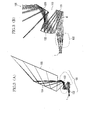
- Fig. 3(A) shows all optical systems of a rear projector which is Embodiment 2 of the present invention.
- Fig. 3(B) shows the structure of a projection optical system 100 which is a main part of all the optical systems.
- Embodiment 2 All the optical systems of Embodiment 2 are composed of a reflective type liquid crystal panel 1, the projection optical system 100, and a single plane mirror 104.
- the projection optical system 100 is formed of a refractive optical system 102 and a reflective optical system 103 similarly to Embodiment 1.
- the refractive optical system 102 is formed of seven rotationally symmetric glass lenses, while the reflective optical system 102 is formed of three reflective surfaces (mirrors) 131 to 133.
- An intermediate image forming surface M is provided between the first reflective surface 131 and the second reflective surface 132.
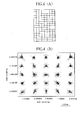
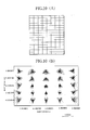
- Fig. 4(B) illustrates performance of image formation on a screen of the projection optical system of Embodiment 2.
- the horizontal axis and vertical axis are the same as those in Fig. 2(B).
- Fig. 4(A) shows distortion of an image on the screen. It can be seen from Fig. 4(A) that distortion can be corrected favorably by the projection optical system of Embodiment 2.
- Fig. 5 shows the structure of a projection optical system 200 which is a main part of all optical systems of a rear projector which is Embodiment 3 of the present invention.
- Reference numeral 1 shows a reflective type liquid crystal panel.
- the projection optical system 200 is formed of a refractive optical system 202 and a reflective optical system 203 similarly to Embodiment 1.
- the refractive optical system 202 is formed of six rotationally symmetric glass lenses, while the reflective optical system 203 is formed of five reflective surfaces (mirrors) 231 to 235.
- An intermediate image forming surface M is provided closer to the fourth reflective surface 234 between the fourth reflective surface 234 and the fifth reflective surface 235.
- Fig. 6(B) illustrates performance of image formation on a screen of the projection optical system of Embodiment 3.
- the horizontal axis and the vertical axis in Fig. 6(B) are the same as those in Fig. 2(B).
- Fig. 6(A) shows distortion of an image on the screen. It can be seen from Fig. 6(A) that distortion can be corrected favorably by the projection optical system of Embodiment 3.
- Fig. 7 shows the structure of a projection optical system 300 which is a main part of all optical systems of a rear projector which is Embodiment 4 of the present invention.
- Reference numeral 1 shows a reflective type liquid crystal panel.
- the projection optical system 300 is formed of a refractive optical system 302 and a reflective optical system 303 similarly to Embodiment 1.
- the refractive optical system 302 is formed of five rotationally symmetric glass lenses, while the reflective optical system 303 is formed of four reflective surfaces (mirrors) 331 to 334.
- the light is incident on the first reflective surface 331 at a small height of light rays, and varying optical powers depending on the azimuth are not easily provided in the reflective optical system 300.
- an intermediate image forming surface M is formed to extend on both sides of the third reflective surface 333.
- Fig. 8(B) illustrates performance of image formation on a screen of the projection optical system of Embodiment 4.
- the horizontal axis and the vertical axis in Fig. 8(B) are the same as those in Fig. 2(B).
- Fig. 8(A) shows distortion of an image on the screen. It can be seen from Fig. 8(A) that distortion can be corrected favorably by the projection optical system of Embodiment 4.
- Fig. 9 shows the structure of a projection optical system 400 which is a main part of all optical systems of a rear projector which is Embodiment 5 of the present invention.
- Reference numeral 1 shows a reflective type liquid crystal panel.
- the projection optical system 400 is formed of a refractive optical system 402 and a reflective optical system 403 similarly to Embodiment 1.
- the refractive optical system 402 is formed of five rotationally symmetric glass lenses, while the reflective optical system 403 is formed of four reflective surfaces (mirrors) 431 to 434.
- the light is incident on the first reflective surface 431 at a large height of light rays, but off-axis light rays are subjected to less refraction due to the large focal length. This results in less divergence of the overall luminous flux, so that the first reflective surface 431 can be formed with small dimensions.
- the value determined in the expression (2) as the condition of the focal lengths is 8.0 (
- 8.0).
- an intermediate image forming surface M is formed to extend on both sides of the third reflective surface 433.
- Fig. 10(B) illustrates performance of image formation on a screen of the projection optical system of Embodiment 5.
- the horizontal axis and the vertical axis in Fig. 10(B) are the same as those in Fig. 2(B).
- Fig. 10(A) shows distortion of an image on the screen. It can be seen from Fig. 10(A) that distortion can be corrected favorably by the projection optical system of Embodiment 5.
- n (n:) is an integer, it represents a surface number.
- OBJ Object surface
- STO aperture stop surface
- IMG image surface
- STO the integer corresponding to n is omitted, and the surface number thereof is determined by adding one to the number n of the preceding surface.
- RDY represents a radius of curvature of the surface.
- THI represents a spacing between the surface and the next surface.
- RMD represents a reflection mode of the surface. Numerical Examples below show data only in the reflection mode in which all light rays incident on the surface are reflected.
- XDE, YDE, and ZDE represent an amount of shifting of the origin of a surface shape from the origin of coordinates of a first surface serving as a reference, and specifically, represent the shifting in a +x direction, a +y direction, and a +z direction, respectively.
- ADE, BDE, and CDE represent an amount of tilt of the origin of a surface with respect to the origin of coordinates of the first surface serving as a reference, and specifically, represent the tilt in a -x direction, a -y direction, and a +z direction, respectively, in a right-handed direction.
- GLB Gn the origin and coordinates of a surface are represented by decentering from the origin and coordinates of an Sn surface by the amounts of XDE, YDE, ZDE, ADE, BDE, and CDE.
- DAR when GLB Gn is not specified for a surface, the position of the origin and coordinates of the next surface to the surface are defined by a coordinate system with no decentering from the surface. The origin and coordinates of the next surface are shifted parallel in the +Z direction by a spacing between surfaces specified by THI of the surface.
- GLA represents a glass name of a surface represented by a surface number.
- a blank in the field of the glass name means air.
- This data means the origin of a fourteenth surface positioned on coordinates shifted from the origin of the first surface relative to the coordinates of the first surface by the amounts of 0 in the +x direction, -0.174089 in the +y direction, and 86.646241 in the +z direction, and a right-handed orthogonal coordinate system tilted in a right-handed direction by 0 degrees in the -x direction, the -y direction, and +z direction.
- the radius of curvature is 85.13274.
- the origin and coordinates of the next surface are at positions shifted parallel in the +z direction by 5.000000 from the origin and coordinates of the fourteenth surface.
- the surface number is 13 which means a thirteenth surface.
- Cjk (j and k are integers equal to or larger than zero)
- C42: -5.0835E-12 it means that -5.0835E-12 is substituted into the coefficient C42 in the expression (1).
- E-X represents " ⁇ 10 -x ''.
- the function derived by similarly substituting all coefficients Cjk into the expression (1) represents the shape of the surface.
- Example 1 Example 2 Example 3 Example 4 Example 5 Expression(2)
- the plane including the central principal ray reflected by the plurality of reflective surfaces (having optical powers) is perpendicular to the screen (the projection surface).
- the plane including the central principal ray may be substantially parallel to the screen.
- the normal line to the image display surface of the image forming element an image display device such as a reflective type liquid crystal panel, a transmissive type liquid crystal panel, a DMD, and a self-light-emission element
- the normal line to the image display surface of the image forming element an image display device such as a reflective type liquid crystal panel, a transmissive type liquid crystal panel, a DMD, and a self-light-emission element
- a reflective member such as a plane mirror with no optical power can be used between the screen and the final reflective surface (the surface closest to the screen having an optical power) among the plurality of reflective surfaces to direct the optical path of the central principal ray toward the screen.
- This enables the optical path to be folded while the characteristics of the present invention are maintained, thereby achieving a further reduction in size and thickness of the whole apparatus.
- two or three plane mirrors may be used.
- the optical axis of the refractive optical system may be substantially parallel to the screen or may be substantially perpendicular to the normal line to the screen.
- the normal line to the plane including the reference axis within the reflective optical system may be substantially perpendicular to the normal line to the screen.
- the normal line to the plane including the reference axis within the reflective optical system may be substantially parallel to the normal line to the screen.
- the projection optical system and the projection type image display apparatus in which the reflective optical system receives the luminous flux with a large width emerging from the original image and passing through the refractive optical system, and excellent performance of image formation can be provided even with a small F number.
- the reflective optical system is formed of the plurality of reflective surfaces to favorably correct the astigmatic difference, curvature of field, distortion, and trapezoidal distortion which require considerable correction due to the oblique projection at a large angle with respect to the projection surface, and the projection distance is short.
- the distortion due to the oblique projection can be corrected near the image forming surface. This also can reduce the size of the reflective surface.
- the intermediate image forming surface When the intermediate image forming surface is formed within the reflective optical system, luminous flux for each field angle can be narrowed at the intermediate image forming surface, so that the size of the reflective surfaces can be reduced.
- the distortion and trapezoidal distortion can be corrected favorably with less influence on the spherical aberration and comatic aberration.
- the projection optical system may have at least one reflective surface among the optical surfaces having optical powers disposed immediately before or after the intermediate image forming surface. This arrangement enables correction of the distortion and trapezoidal distortion with a small number of the optical surfaces.
- the projection optical system may have a reflective surface as the optical surface having an optical power closest to the intermediate image forming surface to allow correction of the distortion and trapezoidal distortion without affecting the spherical aberration and comatic aberration.
- the reflective surfaces formed of rotationally asymmetric surfaces can provide varying image magnifications depending on the azimuthal direction. Consequently, the distortion and trapezoidal distortion due to the oblique projection can be reduced.
- At least one of the optical surfaces having optical powers disposed immediately before and after the intermediate image forming surface may have an asymmetric optical power in the azimuthal directions of 0 and 90 degrees, thereby making it possible to set different focal lengths depending on the azimuthal direction on the projection surface. It is thus possible to realize the projection optical system which can correct the distortion even at a large angle between the central principal ray and the projection surface.
- each of the optical surfaces having optical powers disposed immediately before and after the intermediate image forming surface may be shaped in the azimuthal directions of 0 and 90 degrees such that the surface has a concave shape toward each azimuthal direction when the refractive optical system has negative curvature of field and the surface has a convex shape toward each azimuthal direction when the refractive optical system has positive curvature of field.
- This can realize the projection optical system which can correct the distortion with a small number of optical surfaces even at a large angle formed between the central principal ray and the projection surface.
- the flat reflective surface provided on the optical path from the reflective optical system to the projection surface may fold and project luminous flux emerging from the reflective optical system onto the projection surface inclined with respect to the central principal ray.
- a large image can be provided even with a small depth of the apparatus.
Landscapes
- Physics & Mathematics (AREA)
- General Physics & Mathematics (AREA)
- Optics & Photonics (AREA)
- Lenses (AREA)
- Projection Apparatus (AREA)
Applications Claiming Priority (2)
| Application Number | Priority Date | Filing Date | Title |
|---|---|---|---|
| JP2002221770 | 2002-07-30 | ||
| JP2002221770A JP2004061959A (ja) | 2002-07-30 | 2002-07-30 | 投射光学系、投射型画像表示装置および画像表示システム |
Publications (2)
| Publication Number | Publication Date |
|---|---|
| EP1387207A2 true EP1387207A2 (de) | 2004-02-04 |
| EP1387207A3 EP1387207A3 (de) | 2004-04-07 |
Family
ID=30112933
Family Applications (1)
| Application Number | Title | Priority Date | Filing Date |
|---|---|---|---|
| EP03254754A Withdrawn EP1387207A3 (de) | 2002-07-30 | 2003-07-29 | Optisches Projektionssystem, Projektionsbildanzeigevorrichtung, und Bildanzeigesystem |
Country Status (2)
| Country | Link |
|---|---|
| EP (1) | EP1387207A3 (de) |
| JP (1) | JP2004061959A (de) |
Cited By (4)
| Publication number | Priority date | Publication date | Assignee | Title |
|---|---|---|---|---|
| EP1901106A3 (de) * | 2006-09-15 | 2008-04-16 | Ricoh Company, Ltd. | Optisches Projektionssystem mit zwei Subsystemen mit einem Dazwischenbild |
| CN102906619A (zh) * | 2010-05-27 | 2013-01-30 | 佳能株式会社 | 反射折射系统和图像拾取装置 |
| EP2587311A3 (de) * | 2011-10-31 | 2016-09-07 | Ricoh Company, Ltd. | Bildanzeigevorrichtung mit katadioptrischem Projektionsobjektiv |
| CN107894690A (zh) * | 2017-10-27 | 2018-04-10 | 上海理鑫光学科技有限公司 | 一种结构光三维测量中的投影系统 |
Families Citing this family (8)
| Publication number | Priority date | Publication date | Assignee | Title |
|---|---|---|---|---|
| JP4210314B2 (ja) * | 2003-02-06 | 2009-01-14 | 株式会社リコー | 投射光学系、拡大投射光学系、拡大投射装置及び画像投射装置 |
| JP4223936B2 (ja) | 2003-02-06 | 2009-02-12 | 株式会社リコー | 投射光学系、拡大投射光学系、拡大投射装置及び画像投射装置 |
| JP2006138882A (ja) * | 2004-11-10 | 2006-06-01 | Konica Minolta Opto Inc | 斜め投影光学系 |
| JP2008096983A (ja) | 2006-09-15 | 2008-04-24 | Ricoh Co Ltd | 投射光学系及び画像投射装置 |
| JP4329863B2 (ja) * | 2007-02-14 | 2009-09-09 | コニカミノルタオプト株式会社 | 投影光学系及び画像投影装置 |
| US7922340B2 (en) | 2007-02-14 | 2011-04-12 | Konica Minolta Opto, Inc. | Projection optical system with enlargement at a varying magnification |
| JP6048056B2 (ja) * | 2012-10-15 | 2016-12-21 | 株式会社ニコン | 反射屈折撮影レンズ |
| WO2022044674A1 (ja) * | 2020-08-28 | 2022-03-03 | 富士フイルム株式会社 | 反射光学系および投写型表示装置 |
Family Cites Families (3)
| Publication number | Priority date | Publication date | Assignee | Title |
|---|---|---|---|---|
| JP4419243B2 (ja) * | 2000-01-31 | 2010-02-24 | コニカミノルタオプト株式会社 | 斜め投影光学系 |
| JP3840031B2 (ja) * | 2000-03-09 | 2006-11-01 | キヤノン株式会社 | 投射光学系及びそれを用いた投射型表示装置 |
| JP3631182B2 (ja) * | 2001-09-04 | 2005-03-23 | キヤノン株式会社 | 画像投射装置 |
-
2002
- 2002-07-30 JP JP2002221770A patent/JP2004061959A/ja active Pending
-
2003
- 2003-07-29 EP EP03254754A patent/EP1387207A3/de not_active Withdrawn
Cited By (7)
| Publication number | Priority date | Publication date | Assignee | Title |
|---|---|---|---|---|
| EP1901106A3 (de) * | 2006-09-15 | 2008-04-16 | Ricoh Company, Ltd. | Optisches Projektionssystem mit zwei Subsystemen mit einem Dazwischenbild |
| US7946717B2 (en) | 2006-09-15 | 2011-05-24 | Ricoh Company, Ltd. | Projection optical system and image projecting apparatus |
| CN102906619A (zh) * | 2010-05-27 | 2013-01-30 | 佳能株式会社 | 反射折射系统和图像拾取装置 |
| CN102906619B (zh) * | 2010-05-27 | 2015-01-14 | 佳能株式会社 | 反射折射系统和图像拾取装置 |
| US9019633B2 (en) | 2010-05-27 | 2015-04-28 | Canon Kabushiki Kaisha | Catadioptric system and image pickup apparatus |
| EP2587311A3 (de) * | 2011-10-31 | 2016-09-07 | Ricoh Company, Ltd. | Bildanzeigevorrichtung mit katadioptrischem Projektionsobjektiv |
| CN107894690A (zh) * | 2017-10-27 | 2018-04-10 | 上海理鑫光学科技有限公司 | 一种结构光三维测量中的投影系统 |
Also Published As
| Publication number | Publication date |
|---|---|
| JP2004061959A (ja) | 2004-02-26 |
| EP1387207A3 (de) | 2004-04-07 |
Similar Documents
| Publication | Publication Date | Title |
|---|---|---|
| US6951395B2 (en) | Projection optical system, projection type image display apparatus, and image display system | |
| US6626541B2 (en) | Projection optical system and projection type displaying apparatus using the same | |
| US9983394B2 (en) | Projection optical system and image display apparatus | |
| US7631975B2 (en) | Projection optical system, magnification projection optical system, magnification projection apparatus, and image projection apparatus | |
| EP2073050B1 (de) | Optisches Projektionssystem mit zwei Subsystemen mit einem Dazwischenbild | |
| US6950240B2 (en) | Imaging optical system | |
| EP1806612B1 (de) | Optisches projektionssystem und projektionsbildanzeigevorrichtung | |
| US6989936B2 (en) | Variable power optical system | |
| US6984044B2 (en) | Projection optical system, projection type image display apparatus, and image display system | |
| US20100079733A1 (en) | Optical engine and wide angle projection lens module thereof | |
| JP2007079524A (ja) | 投射光学系及び投射型画像表示装置 | |
| CN102087463A (zh) | 投射型显示装置 | |
| US20100097581A1 (en) | Projection optical system | |
| US20100118281A1 (en) | Projection optical system | |
| JP2008090200A (ja) | ズームレンズおよび投射型画像表示装置 | |
| EP1387207A2 (de) | Optisches Projektionssystem, Projektionsbildanzeigevorrichtung, und Bildanzeigesystem | |
| JP5102940B2 (ja) | 投写映像表示装置及びそれに用いられる投写光学ユニット | |
| US7086742B2 (en) | Projection optical system | |
| US6991338B2 (en) | Projection optical system, projection type image display apparatus, and image display system | |
| JP4973793B2 (ja) | 投写光学ユニット | |
| CN100417969C (zh) | 投影光学系统及投影型图像显示装置 | |
| JP4551674B2 (ja) | 変倍光学系 | |
| JP2005189768A (ja) | 投射光学系、画像投射装置 |
Legal Events
| Date | Code | Title | Description |
|---|---|---|---|
| PUAI | Public reference made under article 153(3) epc to a published international application that has entered the european phase |
Free format text: ORIGINAL CODE: 0009012 |
|
| AK | Designated contracting states |
Kind code of ref document: A2 Designated state(s): AT BE BG CH CY CZ DE DK EE ES FI FR GB GR HU IE IT LI LU MC NL PT RO SE SI SK TR |
|
| AX | Request for extension of the european patent |
Extension state: AL LT LV MK |
|
| PUAL | Search report despatched |
Free format text: ORIGINAL CODE: 0009013 |
|
| AK | Designated contracting states |
Kind code of ref document: A3 Designated state(s): AT BE BG CH CY CZ DE DK EE ES FI FR GB GR HU IE IT LI LU MC NL PT RO SE SI SK TR |
|
| AX | Request for extension of the european patent |
Extension state: AL LT LV MK |
|
| RIC1 | Information provided on ipc code assigned before grant |
Ipc: 7G 02B 17/08 B Ipc: 7G 02B 27/18 A |
|
| 17P | Request for examination filed |
Effective date: 20040819 |
|
| AKX | Designation fees paid |
Designated state(s): DE FR GB IT NL |
|
| 17Q | First examination report despatched |
Effective date: 20041203 |
|
| STAA | Information on the status of an ep patent application or granted ep patent |
Free format text: STATUS: THE APPLICATION HAS BEEN WITHDRAWN |
|
| 18W | Application withdrawn |
Effective date: 20060717 |