EP1387371A2 - Bouton rotatif et escamotable - Google Patents
Bouton rotatif et escamotable Download PDFInfo
- Publication number
- EP1387371A2 EP1387371A2 EP03011391A EP03011391A EP1387371A2 EP 1387371 A2 EP1387371 A2 EP 1387371A2 EP 03011391 A EP03011391 A EP 03011391A EP 03011391 A EP03011391 A EP 03011391A EP 1387371 A2 EP1387371 A2 EP 1387371A2
- Authority
- EP
- European Patent Office
- Prior art keywords
- household appliance
- retractable
- rotary
- switched
- unit according
- Prior art date
- Legal status (The legal status is an assumption and is not a legal conclusion. Google has not performed a legal analysis and makes no representation as to the accuracy of the status listed.)
- Withdrawn
Links
Images

Classifications
-
- H—ELECTRICITY
- H01—ELECTRIC ELEMENTS
- H01H—ELECTRIC SWITCHES; RELAYS; SELECTORS; EMERGENCY PROTECTIVE DEVICES
- H01H3/00—Mechanisms for operating contacts
- H01H3/02—Operating parts, i.e. for operating driving mechanism by a mechanical force external to the switch
- H01H3/08—Turn knobs
-
- H—ELECTRICITY
- H01—ELECTRIC ELEMENTS
- H01H—ELECTRIC SWITCHES; RELAYS; SELECTORS; EMERGENCY PROTECTIVE DEVICES
- H01H25/00—Switches with compound movement of handle or other operating part
- H01H25/06—Operating part movable both angularly and rectilinearly, the rectilinear movement being along the axis of angular movement
-
- H—ELECTRICITY
- H01—ELECTRIC ELEMENTS
- H01H—ELECTRIC SWITCHES; RELAYS; SELECTORS; EMERGENCY PROTECTIVE DEVICES
- H01H3/00—Mechanisms for operating contacts
- H01H3/02—Operating parts, i.e. for operating driving mechanism by a mechanical force external to the switch
- H01H3/16—Operating parts, i.e. for operating driving mechanism by a mechanical force external to the switch adapted for actuation at a limit or other predetermined position in the path of a body, the relative movement of switch and body being primarily for a purpose other than the actuation of the switch, e.g. for a door switch, a limit switch, a floor-levelling switch of a lift
Definitions
- the invention relates to a retractable rotary toggle unit the preamble of claim 1.
- rotary selector switches for setting work programs and / or program parameters provided.
- These rotary selector switches are common in a control panel unit behind a switch panel arranged and can be turned using a rotary knob, which is placed in front of the switch panel. Arranging in front of the switch panel is for manual operation essential.
- this is Setting the work programs or program parameters or after switching on a main switch of the device.
- a main switch often consists of one Pushbutton switch next to the rotary knob on the switch panel is arranged.
- the retractable rotary toggle unit is preferably designed such that that the home appliance is turned off in the sunken position is. Alternatively, however, it can be provided that the household appliance does not always come with the transfer the rotary toggle unit in its lowered position in the switched off state, but that initially an ongoing work program is ended according to the program before the device is switched off.
- the household appliance after the transfer the rotary toggle unit from its lowered position to yours protruding position can be switched on or already in this state is switched on. This ensures that it can be switched on be that the home appliance in the sense of a standby mode still waiting for program input before the entered one Work program is started.
- a defined or by the user of the Household appliance definable standard work program or a program part after switching on the household appliance by pulling out the retractable toggle, preferably immediately is started.
- Many users vary in their Choice of work program very little, so in the vast majority Number of program runs only one work program is used as standard.
- Such a standard program is particularly suitable immediately after switching on of the device, if necessary after waiting for a possible change, directly or by pressing one separate or included in the rotary knob unit Start function to be started.
- At least one switch on the rotary toggle unit coupled by a to a shaft of the rotary knob unit arranged actuator switched becomes.
- This actuator performs in particular the same axial stroke as the rotary knob when sinking or bring out.
- this is at least a switch a microswitch that is preferred by one ramp-shaped actuating device switchable is.
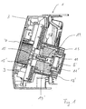
- a household washing machine not shown, has one Control panel unit 1 with a switch panel 3, which Includes controls and indicators.
- One of these controls is a rotary selector switch 5 which is used for setting Wash programs and also individual program parameters provided is.
- This rotary selector switch 5 has a rotary knob 7 on that for actuating the rotary selector switch 5 with the Hand serves.
- This rotary knob 7 can be from one in the figures 1 and 2 shown in a protruding position Transfer position, which by means of an overtravel function, comparable to a ballpoint pen mechanism, guaranteed is. Only in the extracted position According to FIG. 3 it is possible to operate the rotary selector switch, since in the recessed position (see Figure 1) the front rotary knob surface is in a flush position with the switch panel.
- the lowering function of the rotary knob unit has the task to provide an attractive design, still a main switch function, with which the washing machine is switched on and off becomes.
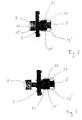
- the retractable body 9 on the fixed body Rotary knob unit 7 two microswitches 11, 11 'arranged.
- Each of these microswitches 11, 11 ' has a two-pole Connection contact 13, 13 'on, each microswitch a pole L or N of the power supply switches, so that All-pole switching on and off is possible.
- Both switching plungers 15, 15 'of the microswitches 11, 11' point to Shaft 17 of the retractable rotary toggle, which together with the rotary knob. 7 is axially movable. There are 17 on this shaft two switching ramps 19, 19 'rigidly coupled and are with this axially guided. Are in the recessed state of the rotary knob 7 the switching ramps 19, 19 'away from the switching plungers 15, 15 ', so that the latter relaxes and the microswitch 11, 11 'are switched off. If the rotary knob 7 in his exposed position transferred, so operate the switching ramps 19, 19 'the respective switching plunger 15, 15' of the microswitch 11, 11 '. The household washing machine is thus on all poles the power supply connected. The device is reversed when the rotary knob 7 is lowered again from the power supply Cut. After switching on the washing machine the user can make a program selection in the usual way.
Landscapes
- Rotary Switch, Piano Key Switch, And Lever Switch (AREA)
- Detail Structures Of Washing Machines And Dryers (AREA)
- Mechanical Control Devices (AREA)
Priority Applications (1)
| Application Number | Priority Date | Filing Date | Title |
|---|---|---|---|
| EP12007018A EP2546845A3 (fr) | 2002-08-03 | 2003-05-20 | Bouton rotatif et escamotable |
Applications Claiming Priority (2)
| Application Number | Priority Date | Filing Date | Title |
|---|---|---|---|
| DE2002135694 DE10235694A1 (de) | 2002-08-03 | 2002-08-03 | Versenkbare Drehknebeleinheit |
| DE10235694 | 2002-08-03 |
Publications (2)
| Publication Number | Publication Date |
|---|---|
| EP1387371A2 true EP1387371A2 (fr) | 2004-02-04 |
| EP1387371A3 EP1387371A3 (fr) | 2005-09-28 |
Family
ID=30010596
Family Applications (2)
| Application Number | Title | Priority Date | Filing Date |
|---|---|---|---|
| EP03011391A Withdrawn EP1387371A3 (fr) | 2002-08-03 | 2003-05-20 | Bouton rotatif et escamotable |
| EP12007018A Withdrawn EP2546845A3 (fr) | 2002-08-03 | 2003-05-20 | Bouton rotatif et escamotable |
Family Applications After (1)
| Application Number | Title | Priority Date | Filing Date |
|---|---|---|---|
| EP12007018A Withdrawn EP2546845A3 (fr) | 2002-08-03 | 2003-05-20 | Bouton rotatif et escamotable |
Country Status (2)
| Country | Link |
|---|---|
| EP (2) | EP1387371A3 (fr) |
| DE (1) | DE10235694A1 (fr) |
Cited By (1)
| Publication number | Priority date | Publication date | Assignee | Title |
|---|---|---|---|---|
| EP1647774A2 (fr) | 2004-10-12 | 2006-04-19 | BSH Bosch und Siemens Hausgeräte GmbH | Dispositif de commande |
Families Citing this family (3)
| Publication number | Priority date | Publication date | Assignee | Title |
|---|---|---|---|---|
| DE102004055945A1 (de) * | 2004-11-19 | 2006-05-24 | BSH Bosch und Siemens Hausgeräte GmbH | Dunstabzugsvorrichtung und Verfahren zum Belüften einer Kochfläche |
| DE102010063995A1 (de) | 2010-12-22 | 2012-06-28 | BSH Bosch und Siemens Hausgeräte GmbH | Elektrisches Haushaltsgerät mit einer Bedienblende |
| EP3380912B1 (fr) * | 2015-11-23 | 2021-10-06 | Bombardier Inc. | Système et procédé de commande de fonctions dans une cabine de véhicule |
Citations (7)
| Publication number | Priority date | Publication date | Assignee | Title |
|---|---|---|---|---|
| DE2364667A1 (de) | 1973-12-24 | 1975-06-26 | Neff Werke | Schalterblende mit betaetigungsknebel |
| DE8428301U1 (de) | 1984-09-26 | 1985-10-24 | Licentia Patent-Verwaltungs-Gmbh, 6000 Frankfurt | Versenkbarer Drehknebel |
| DE4203427A1 (de) | 1992-02-06 | 1993-08-12 | Haschkamp Ernestine | Nockendrehschalter |
| EP0709513A1 (fr) | 1994-10-26 | 1996-05-01 | Merloni Elettrodomestici S.p.A. | Machines à laver et/ou à sécher incorporant un éclairage |
| DE19722044A1 (de) | 1997-05-27 | 1998-12-03 | Kueppersbusch | Gargerät, insbesondere Backofen |
| EP0936643A2 (fr) | 1998-02-11 | 1999-08-18 | BSH Bosch und Siemens Hausgeräte GmbH | Ensemble interrupteur rotatif pour appareils de ménage électriques |
| JP2000315431A (ja) | 1999-04-28 | 2000-11-14 | Mitsubishi Electric Corp | スイッチ連動型伸縮式ツマミ |
Family Cites Families (2)
| Publication number | Priority date | Publication date | Assignee | Title |
|---|---|---|---|---|
| US4948928A (en) * | 1989-08-16 | 1990-08-14 | Eaton Corporation | Push/push reset programmer |
| GB2260026B (en) * | 1991-09-27 | 1995-01-04 | Gibbs & Hill Limited | Dual function electrical control unit |
-
2002
- 2002-08-03 DE DE2002135694 patent/DE10235694A1/de not_active Withdrawn
-
2003
- 2003-05-20 EP EP03011391A patent/EP1387371A3/fr not_active Withdrawn
- 2003-05-20 EP EP12007018A patent/EP2546845A3/fr not_active Withdrawn
Patent Citations (7)
| Publication number | Priority date | Publication date | Assignee | Title |
|---|---|---|---|---|
| DE2364667A1 (de) | 1973-12-24 | 1975-06-26 | Neff Werke | Schalterblende mit betaetigungsknebel |
| DE8428301U1 (de) | 1984-09-26 | 1985-10-24 | Licentia Patent-Verwaltungs-Gmbh, 6000 Frankfurt | Versenkbarer Drehknebel |
| DE4203427A1 (de) | 1992-02-06 | 1993-08-12 | Haschkamp Ernestine | Nockendrehschalter |
| EP0709513A1 (fr) | 1994-10-26 | 1996-05-01 | Merloni Elettrodomestici S.p.A. | Machines à laver et/ou à sécher incorporant un éclairage |
| DE19722044A1 (de) | 1997-05-27 | 1998-12-03 | Kueppersbusch | Gargerät, insbesondere Backofen |
| EP0936643A2 (fr) | 1998-02-11 | 1999-08-18 | BSH Bosch und Siemens Hausgeräte GmbH | Ensemble interrupteur rotatif pour appareils de ménage électriques |
| JP2000315431A (ja) | 1999-04-28 | 2000-11-14 | Mitsubishi Electric Corp | スイッチ連動型伸縮式ツマミ |
Cited By (2)
| Publication number | Priority date | Publication date | Assignee | Title |
|---|---|---|---|---|
| EP1647774A2 (fr) | 2004-10-12 | 2006-04-19 | BSH Bosch und Siemens Hausgeräte GmbH | Dispositif de commande |
| EP1647774A3 (fr) * | 2004-10-12 | 2010-01-06 | BSH Bosch und Siemens Hausgeräte GmbH | Dispositif de commande |
Also Published As
| Publication number | Publication date |
|---|---|
| EP2546845A2 (fr) | 2013-01-16 |
| EP2546845A3 (fr) | 2013-03-13 |
| DE10235694A1 (de) | 2004-02-19 |
| EP1387371A3 (fr) | 2005-09-28 |
Similar Documents
| Publication | Publication Date | Title |
|---|---|---|
| DE3338064C2 (fr) | ||
| DE69906932T2 (de) | Elektrisch betriebenes haushaltsgerät, insbesondere handmixer | |
| DE19729459A1 (de) | Endoskopisches, chirurgisches Gerät | |
| DE19712048C2 (de) | Bedienvorrichtung | |
| DE4215097C2 (de) | Schalteranordnung | |
| DE69607064T2 (de) | Steuerungssystem, insbesondere für Geräte die Dampf erzeugen für Haushalts und/oder gewerbliche Reinigung | |
| DE3039584C2 (de) | Regulierhebel, insbesondere zur Vorwahl der Fahrgeschwindigkeit an selbstfahrenden landwirtschaftlichen Maschinen | |
| EP1387371A2 (fr) | Bouton rotatif et escamotable | |
| EP4103884A1 (fr) | Dispositif de commande d'opérateur comprenant un élément de commande d'opérateur à composants multiples, et appareil ménager et procédé de fonctionnement d'un appareil ménager | |
| WO2005066547A2 (fr) | Appareil de cuisson avec un parametre, programme et/ou mode de fonctionnement predetermine | |
| DE602004013191T2 (de) | Elektrowerkzeug mit doppelt steuerbarem schalter | |
| DE1054863B (de) | Schalter fuer einen Scheibenwischer-antriebsmotor und den Motor einer Spuelgeraetpumpe fuer Windschutzscheiben | |
| DE2904159C2 (de) | Elektrisches Handgerät, wie Elektromesser, Handrührer o.dgl. | |
| EP1459339A1 (fr) | Dispositif de commutation par paliers electromecanique presentant des fonctions supplementaires temporisees | |
| EP1008809B1 (fr) | Dispositif de commande d'appareils électroménagers, en particulier de fours | |
| DE19909100C2 (de) | Thermostatventilaufsatz | |
| DE60126037T2 (de) | Steuervorrichtung mit Taste | |
| DE2805553C2 (de) | Programmwähler und Programmfortschrittanzeigevorrichtung | |
| DE3243723A1 (de) | Leistungssteuerung fuer einen staubsauger, insbesondere bodenstaubsauger | |
| DE202004006163U1 (de) | Dusch-Armatur | |
| DE3919947C2 (fr) | ||
| DE19948754A1 (de) | Waage mit motorisch betätigbarem Windschutz | |
| EP2015163B1 (fr) | Procédé de transmission de signaux et dispositif d'exécution d'un tel procédé | |
| DE922957C (de) | Drucktastenschalter, insbesondere zur Wellenbereichumschaltung in Rundfunk-Empfaengern | |
| DE2118681C3 (de) | Elektrischer Schalter |
Legal Events
| Date | Code | Title | Description |
|---|---|---|---|
| PUAI | Public reference made under article 153(3) epc to a published international application that has entered the european phase |
Free format text: ORIGINAL CODE: 0009012 |
|
| AK | Designated contracting states |
Kind code of ref document: A2 Designated state(s): AT BE BG CH CY CZ DE DK EE ES FI FR GB GR HU IE IT LI LU MC NL PT RO SE SI SK TR |
|
| AX | Request for extension of the european patent |
Extension state: AL LT LV MK |
|
| PUAL | Search report despatched |
Free format text: ORIGINAL CODE: 0009013 |
|
| AK | Designated contracting states |
Kind code of ref document: A3 Designated state(s): AT BE BG CH CY CZ DE DK EE ES FI FR GB GR HU IE IT LI LU MC NL PT RO SE SI SK TR |
|
| AX | Request for extension of the european patent |
Extension state: AL LT LV MK |
|
| 17P | Request for examination filed |
Effective date: 20060314 |
|
| AKX | Designation fees paid |
Designated state(s): DE FR GB IT |
|
| 17Q | First examination report despatched |
Effective date: 20101001 |
|
| RAP1 | Party data changed (applicant data changed or rights of an application transferred) |
Owner name: ELECTROLUX HOME PRODUCTS CORPORATION N.V. |
|
| RAP1 | Party data changed (applicant data changed or rights of an application transferred) |
Owner name: ELECTROLUX HOME PRODUCTS CORPORATION N.V. |
|
| STAA | Information on the status of an ep patent application or granted ep patent |
Free format text: STATUS: THE APPLICATION IS DEEMED TO BE WITHDRAWN |
|
| 18D | Application deemed to be withdrawn |
Effective date: 20150509 |