EP1387562A2 - Tragbares Gerät mit belichtungsabhäniger Bildaufnahmevorrichtung und Gerät zur Einstellung der Belichtung - Google Patents
Tragbares Gerät mit belichtungsabhäniger Bildaufnahmevorrichtung und Gerät zur Einstellung der Belichtung Download PDFInfo
- Publication number
- EP1387562A2 EP1387562A2 EP03016076A EP03016076A EP1387562A2 EP 1387562 A2 EP1387562 A2 EP 1387562A2 EP 03016076 A EP03016076 A EP 03016076A EP 03016076 A EP03016076 A EP 03016076A EP 1387562 A2 EP1387562 A2 EP 1387562A2
- Authority
- EP
- European Patent Office
- Prior art keywords
- exposure
- light emission
- light
- level
- emission quantity
- Prior art date
- Legal status (The legal status is an assumption and is not a legal conclusion. Google has not performed a legal analysis and makes no representation as to the accuracy of the status listed.)
- Ceased
Links
- 230000004044 response Effects 0.000 claims description 4
- 238000000034 method Methods 0.000 description 21
- 230000008569 process Effects 0.000 description 11
- 230000008859 change Effects 0.000 description 5
- 230000006870 function Effects 0.000 description 4
- 238000012545 processing Methods 0.000 description 4
- 238000004891 communication Methods 0.000 description 3
- 238000005286 illumination Methods 0.000 description 3
- 238000003384 imaging method Methods 0.000 description 3
- 238000012544 monitoring process Methods 0.000 description 3
- 238000012937 correction Methods 0.000 description 2
- 230000007423 decrease Effects 0.000 description 1
- 238000010586 diagram Methods 0.000 description 1
- 238000011156 evaluation Methods 0.000 description 1
- 230000005669 field effect Effects 0.000 description 1
- 238000010348 incorporation Methods 0.000 description 1
- 230000010354 integration Effects 0.000 description 1
- 239000004973 liquid crystal related substance Substances 0.000 description 1
- 230000035945 sensitivity Effects 0.000 description 1
Images




Classifications
-
- H—ELECTRICITY
- H04—ELECTRIC COMMUNICATION TECHNIQUE
- H04N—PICTORIAL COMMUNICATION, e.g. TELEVISION
- H04N1/00—Scanning, transmission or reproduction of documents or the like, e.g. facsimile transmission; Details thereof
- H04N1/024—Details of scanning heads ; Means for illuminating the original
- H04N1/028—Details of scanning heads ; Means for illuminating the original for picture information pick-up
- H04N1/02815—Means for illuminating the original, not specific to a particular type of pick-up head
-
- H—ELECTRICITY
- H04—ELECTRIC COMMUNICATION TECHNIQUE
- H04N—PICTORIAL COMMUNICATION, e.g. TELEVISION
- H04N1/00—Scanning, transmission or reproduction of documents or the like, e.g. facsimile transmission; Details thereof
- H04N1/024—Details of scanning heads ; Means for illuminating the original
- H04N1/028—Details of scanning heads ; Means for illuminating the original for picture information pick-up
- H04N1/02815—Means for illuminating the original, not specific to a particular type of pick-up head
- H04N1/0282—Using a single or a few point light sources, e.g. a laser diode
-
- H—ELECTRICITY
- H04—ELECTRIC COMMUNICATION TECHNIQUE
- H04N—PICTORIAL COMMUNICATION, e.g. TELEVISION
- H04N23/00—Cameras or camera modules comprising electronic image sensors; Control thereof
- H04N23/70—Circuitry for compensating brightness variation in the scene
- H04N23/74—Circuitry for compensating brightness variation in the scene by influencing the scene brightness using illuminating means
Definitions
- the present invention relates to a portable device having an image pick-up unit and to an exposure adjusting device and, more specifically, it relates to a portable device having an image pick-up unit that adjusts brightness of an object (hereinafter referred to as exposure) utilizing an auxiliary light source, as well as to an exposure adjusting device.
- This laid-open application discloses a light adjusting device adjusting quantity of light emitted by an auxiliary light source for image pick-up.
- the light adjusting device receives light reflected from the object and adjusts the quantity of light emitted by the light source such that the exposure level detected from an image signal based on a photo reception signal attains to an appropriate level.
- Japanese Patent Laying-Open No. 6-222429 discloses a strobe that automatically adjusts light emission of a flashing discharge tube. Specifically, in accordance with the diaphragm stop at the time of image pick-up, data representing quantity of strobe light emission corresponding to appropriate exposure is set, and the set data is input to one side of a comparator. To the other side of the comparator, data representing a result of integration of a current in accordance with the level of the reflected light from the object is input. When the data at the two inputs of the comparator match, emission of light from the flashing discharge tube is stopped.
- Japanese Patent Laying-Open No. 2000-267151 discloses a camera that controls the quantity of stroboscopic light emission. According to this laid-open application, before a normal light emission by a strobe for image pick-up, a preliminary light emission of the strobe is performed to adjust exposure, and in accordance with the result of evaluation of the light reflected from the object at the time of the preliminary light emission, the level of the normal light emission of the strobe is determined.
- Japanese Patent Laying-Open No. 2001-230970 discloses an apparatus that picks-up an image of an object in accordance with image pick-up conditions defined by the position of the object. Specifically, at the time of image pick-up, distance to the object is measured, for example, by a distance measuring sensor, and based on the measured distance, various conditions including the quantity of light emission by a strobe are determined.
- the light adjusting device disclosed in Japanese Utility Model Laying-Open No. 58-83864 is fixedly provided in connection with a television camera fixedly installed at an entrance for picking-up an image of a visitor. Therefore, the quantity of light emission is adjusted simply to compensate for underexposure, while the distance between the light adjusting device and the object and the distance between the camera and the object do not vary. Therefore, it is impossible by the technique described in this reference to adjust the quantity of light emission while linearly following variation in the distance between the camera and the object.
- quantity of light entering an imaging device is controlled by arranging an ND filter in front of the imaging device.
- Japanese Patent Laying-Open No. 60-6930 discloses a method of controlling exposure of a camera. Specifically, exposure of a camera is adjusted by using data of a range that can be regarded as appropriate exposure of a film, data of film sensitivity and data of light intensity from an object.
- the quantity of strobe light emission is determined such that the optimal exposure is attained in accordance with the diaphragm stop at the time of image pick-up. Therefore, when the distance between the camera and the object happens to change as the camera moves, for example, the optimal exposure set in accordance with the diaphragm stop would result in under-exposure or over-exposure.
- image pick-up conditions including the quantity of light emission are determined based on the distance to the object detected by a distance measuring sensor. Therefore, the structure of the device becomes complicated by the incorporation of the sensor, and the cost of the device also increases.
- An object of the present invention is to provide a portable device having an image pick-up unit that can attain appropriate exposure level and an exposure adjusting device.
- a portable device having an image pick-up unit picking-up an image and outputting image information, including a light source emitting light to an object, a control unit controlling emission of light by the light source based on the quantity of light emission in an image pick-up mode, and an exposure detecting unit detecting the exposure level based on the image information.
- the control unit includes a light emission quantity determining unit, and a comparing unit comparing an exposure level detected by the exposure detecting unit with the light source emitting light based on the quantity of light emission determined by the light emission quantity determining unit with an exposure level detected by the exposure detecting unit with the light source not emitting light. Based on the result of comparison, the light emission quantity determining unit determines the quantity of light emission.
- the quantity is determined with reference to the result of comparison between the exposure level when the light source emits light with the quantity of light emission as determined for the last time and the exposure level when the light source does not emit light, that is, with reference to two exposure levels.
- the two reference values are relative (opposing) values, that is, the exposure levels with and without light emission from the light source. Therefore, the quantity of light emission can be determined with high accuracy, and the exposure level can be attained with high accuracy.
- the comparing unit compares the exposure level detected by the exposure detecting unit with the light source emitting light with the quantity of light emission determined by the light emission quantity determining unit with the exposure level detected by the exposure detecting unit with the light source not emitting light, and detects a difference.
- the light emission quantity determining unit determines the quantity of light emission to have the exposure level attain the optimal level, based on the difference detected by the comparing unit.
- the quantity is determined with reference to the result of comparison between the exposure level when the light source emits light with the quantity of light emission as determined for the last time with the exposure level when the light source does not emit light, that is, with reference to two exposure levels.
- the quantity of light emission there are two reference values to determine the quantity of light emission, and hence, the quantity of light emission to have the exposure level attain the optimal level can be determined with high accuracy. As a result, the optimum exposure level can be obtained with high accuracy.
- the two reference values are relative (opposing) values, that is, the exposure levels with and without light emission from the light source. Therefore, the quantity of light emission can be determined with high accuracy, and the exposure level can be attained with high accuracy.
- the optimal level mentioned above is the target exposure level related to the image information. Therefore, in the image pick-up mode, the target exposure level can be attained with high accuracy.
- the comparing unit and the light emission quantity determining unit are repeatedly activated.
- the quantity of light emission can be determined following the variation. Therefore, it becomes possible to have the exposure level always matching the optimal level.
- control unit described above further includes a starting state setting unit setting the light source to non-emission state at the start of the image pick-up mode, and a start level determining unit determining whether the exposure level detected by the exposure detecting unit in the non-emission state set by the starting state setting unit matches the optimal level or not.
- start level determining unit determines whether the exposure level detected by the exposure detecting unit in the non-emission state set by the starting state setting unit matches the optimal level or not.
- the light source is set to the non-emission state, whether the exposure level matches the optimal level or not is determined, and when it is determined to be not matching, the light emission quantity determining unit and the comparing unit are activated to execute the repetition of the series of operations.
- the light emission quantity determining unit determines the quantity of light emission to be the maximum quantity that can be attained by the light source.
- the light source emits light with the maximum quantity of light. Therefore, it becomes possible to quickly attain the exposure level matching the optimal level, when an image is to be picked-up in the dark.
- the portable device having the image pick-up unit further has a storing unit for storing image data corresponding to the image information, and when the exposure level detected by the exposure detecting unit matches the optimal level, the image data is stored in the storing unit.
- image data corresponding to that image information which is output when the detected exposure level matches the optimal level is stored in the storing unit. Therefore, the image data of which exposure level matches the optimal level can be stored and held in the storing unit.
- the portable device having the image pick-up unit described above further has a shutter key operated from outside to instruct storage of image data to the storing unit, and when the exposure level detected by the exposure detecting unit matches the optimal level, whether the shutter key is operated or not is determined.
- the image pick-up mode includes a close-up mode and a non-close-up mode that are switchable.
- the image pick-up mode In the image pick-up mode, a series of operations is repeated until the detected exposure level matches the optimal level, in which light is emitted with the quantity of light emission as determined last time, emission of light is stopped immediately thereafter, and the quantity of light emission is determined. Therefore, even when in the image pick-up mode the close-up mode and the non-close-up mode are switched and the distance between the object and the image pick-up unit varies, the quantity of light emission can be determined following the variation. Therefore, it becomes possible to have the exposure level always matching the optimal level.
- the portable device having the image pick-up unit described above further includes a display unit displaying an image in accordance with the image information.
- the light emission quantity determining unit includes a table in which light emission quantities are registered for a plurality of differences, and based on the difference detected by the comparing unit, the table is looked-up and the corresponding light emission quantity is read.
- the light emission quantity determining unit determines the light emission quantity by looking-up the table and reading the corresponding quantity. Accordingly, the light emission quantity can be determined quickly in a simple manner.
- the present invention provides an exposure adjusting device including an exposure detecting unit detecting an exposure level based on image information obtained by picking-up an image of an object, a light emission quantity determining unit determining quantity of light emission by a light source provided in advance for emitting light to the object in an image pick-up mode, and a comparing unit comparing an exposure level detected by the exposure detecting unit with the light source emitting light with the quantity of light emission as determined by the light emission quantity determining unit with an exposure level detected by the exposure detecting unit with the light source not emitting light.
- the light emission quantity determining unit determines the quantity of light emission based on the result of comparison by the comparing unit.
- the quantity is determined with reference to the result of comparison between the exposure level with the light source emitting light with the quantity of light emission as determined for the last time and the exposure level with the light source not emitting light, that is, with reference to two exposure levels.
- the two reference values are relative (opposing) values, that is, the exposure levels with and without light emission from the light source. Therefore, the quantity of light emission can be determined with high accuracy, and the exposure level can be attained with high accuracy.
- the comparing unit compares the exposure level detected by the exposure detecting unit with the light source emitting light with the quantity of light emission determined by the light emission quantity determining unit with the exposure level detected by the exposure detecting unit with the light source not emitting light, and detects a difference.
- the light emission quantity determining unit determines the quantity of light emission to have the exposure level attain the optimal level based on the difference detected by the comparing unit.
- the quantity is determined with reference to the result of comparison between the exposure level with the light source emitting light with the quantity of light emission as determined for the last time with the exposure level with the light source not emitting light, that is, with reference to two exposure levels.
- the quantity of light emission there are two reference values to determine the quantity of light emission, and hence, the quantity of light emission to have the exposure level attain the optimal level can be determined with high accuracy. As a result, the optimum exposure level can be obtained with high accuracy.
- the two reference values are relative (opposing) values, that is, the exposure levels with and without light emission from the light source. Therefore, the quantity of light emission can be determined with high accuracy, and the exposure level can be attained with high accuracy.
- the optimal level mentioned above is the target exposure level related to the image information. Therefore, in the image pick-up mode, the target exposure level can be attained with high accuracy.
- the comparing unit and the light emission quantity determining unit are repeatedly activated.
- the quantity of light emission can be determined following the variation. Therefore, it becomes possible to have the exposure level always matching the optimal level.
- the exposure adjusting device described above further includes a starting state setting unit setting the light source to non-emission state at the start of the image pick-up mode, and a start level determining unit determining whether the exposure level detected by the exposure detecting unit in the non-emission state set by the starting state setting unit matches the optimal level or not.
- the light emission quantity determining unit and the comparing unit are activated.
- the light source is set to the non-emission state, whether the exposure level matches the optimal level or not is determined, and when it is determined to be not matching, the light emission quantity determining unit and the comparing unit are activated to execute the repetition of the series of operations.
- the light emission quantity determining unit determines the quantity of light emission to be the maximum quantity that can be attained by the light source.
- the light source emits light with the maximum quantity of light. Therefore, it becomes possible to quickly attain the exposure level matching the optimal level, when an image is to be picked-up in the dark.
- the image pick-up mode includes a close-up mode and a non-close-up mode that are switchable.
- the image pick-up mode In the image pick-up mode, a series of operations is repeated until the detected exposure level matches the optimal level, in which light is emitted with the quantity of light emission as determined last time, emission of light is stopped immediately thereafter, and the quantity of light emission is determined. Therefore, even when in the image pick-up mode the close-up mode and the non-close-up mode are switched and the distance between the object and the image pick-up unit varies, the quantity of light emission can be determined following the variation. Therefore, it becomes possible to have the exposure level always matching the optimal level.
- the light emission quantity determining unit includes a table in which light emission quantities are registered corresponding to a plurality of differences, and based on the difference detected by the comparing unit, the table is looked-up and the corresponding light emission quantity is read.
- the light emission quantity determining unit determines the light emission quantity by looking-up the table and reading the corresponding quantity. Accordingly, the light emission quantity can be determined quickly in a simple manner.
- the present invention provides an exposure adjusting method, including the exposure detecting step of detecting an exposure level based on image information obtained by picking-up an image of an object, the light emission quantity determining step of determining the quantity of light emission by a light source provided in advance for emitting light to the object, and the difference detecting step of detecting a difference between an exposure level detected by the exposure detecting step with the light source emitting light with the quantity of light emission as determined by the light emission quantity determining step and an exposure level detected by the exposure detecting step without light emission by the light source.
- the quantity of light emission is determined to attain the optimal exposure level, based on the difference detected in the difference detecting step.
- the portable device having an image pick-up unit picking-up an image of an object and outputting image information further includes a light source emitting light to the object, a storing unit storing image data corresponding to the image information, a shutter key, and control means.
- the control means stores the image data corresponding to the image information in the storing unit in response to an operation of the shutter key, and in accordance with the exposure level based on the image information, starts emission of the light source, regardless of the operation of the shutter key.
- the object image can be picked-up while monitoring the object, without requiring any special operation by the user.
- control means sets the light source to a non-emission state, in accordance with the exposure level based on the image information, regardless of the operation of the shutter key, after the start of light emission by the light source.
- a display unit for displaying various pieces of information is further provided, and the control means has the image data corresponding to the image information displayed on the display unit, when the image pick-up mode is set. Therefore, it is possible for the user to monitor the image at the display unit while picking-up an image of the object by a camera.
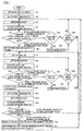
- Fig. 1 shows an exposure level control procedure in the image pick-up mode in accordance with an embodiment of the present invention.
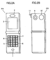
- Figs. 2A and 2B show an appearance of the portable camera-phone PH in accordance with the present embodiment.
- portable camera-phone PH on the front surface, portable camera-phone PH is provided with a microphone 1 for voice communication, a speaker 2 for sound output, an LCD (Liquid Crystal Display) 3 for displaying various information, and operation key unit 4 having various keys to be operated by a user arranged thereon.
- portable camera-phone PH on the back surface, portable camera-phone PH is provided with a camera 9 for picking-up images of an object, and a strobe 10 functioning as an auxiliary light source at the time of an image pick-up.
- the camera-phone further includes a mode switching lever that is operated by a user.
- Image pick-up by camera 9 is either in a close-up mode or a non-close-up mode (hereinafter referred to as a normal mode).
- Mode switching lever 11 is operated to switch operation either to the close-up mode or the normal mode.
- the normal mode is suitable for picking up an image of a normal object 44, while in the close-up mode, camera 9 (lens 91 as will be described later) is positioned close to the object 44 such as bar-codes, to pick-up the image thereof at a relatively close distance to read information precisely from the image data.
- the distance between lens 91 and a CCD array of a CCD circuit 92 which will be described later, is changed such that the image of object 44 is appropriately formed on the CCD array.
- Operation key unit 4 includes an ON/OFF key 5 operated to turn ON/OFF light emission of strobe 10, a shutter key 6 that is turned ON (pressed) to activate a shutter operation of camera 9, and a strobe key 7 pressed to instruct light emission of strobe 10.
- Fig. 3 is a schematic block diagram representing the configuration of portable camera-phone PH.
- portable camera-phone PH includes a control unit 29, and microphone 1, speaker 2, LCD 3, operation key unit 4 and camera 9 described above, that are connected to control unit 29.
- Portable camera-phone PH further includes an antenna 21 transmitting and receiving radio wave, a wireless unit 22 controlling radio communication through antenna 21 in accordance with an instruction from control unit 29, a strobe control circuit 13 controlling light emission operation of strobe 10 in accordance with an instruction from control unit 29, and a storing unit 27 storing information including image data 34, which will be described later.
- shutter key 6 is operated from the outside for instructing storage of image data 34 to storing unit 27, the timing at which the image data 34 is stored in storing unit 27 is the same as the timing of ON operation of shutter key 6.
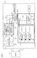
- Fig. 4 shows a circuit configuration related to camera 9 and strobe 10 of the portable camera phone PH.
- camera 9 includes a lens 91, a CCD circuit 92 consisting of a CCD (Charge Coupled Device) array, receiving light reflected from object 44 through lens 91 and outputting an image signal that is an electric signal in accordance with the received light level, and an image circuit 93 receiving as an input the image signal from CCD circuit 92, performing a prescribed process on the input image signal, and outputting image data 34 and total exposure value 31.
- CCD Charge Coupled Device
- Image circuit 93 includes an image processing unit 94 that performs, on the input image signal, white balance adjustment, ⁇ correction, color signal processing, luminance signal processing or the like, converts the result to image data 34 in the form of digital signals and outputs the same, and an exposure control unit 95 outputting total exposure value 31 of the input image signals.
- Control unit 29 has a CPU (Central Processing Unit) 15 and a memory 14 storing various pieces of information.
- CPU 15 executes various processes including a process for displaying the image on LCD 3. Therefore, it is possible for the user to monitor the image on the screen of LCD 3 while picking-up an image of object 44 by camera 9.
- Memory 14 stores, in advance, optimal exposure value 141, MAX value 142 representing the maximum level of light emission that can be attained by strobe 10 and a table TB as can be seen from Fig. 5, and it has an area TE for temporarily storing data.
- the optimal exposure value 141 represents an exposure value that is optimal for camera 9 of portable camera-phone PH to pick-up an image. In other words, it represents the target value of luminance signal level among the image signals of object 44.
- MAX value 142 represents the maximum quantity of light emission when strobe 10 is ON (lit).
- Exposure control unit 95 calculates total exposure value 31 of the image signals successively input from CCD circuit 92, and outputs the calculated value to control unit 29. Specifically, when strobe 10 is turned ON (lit) and images are to be picked-up using strobe 10 as an auxiliary light source, a sum of luminance signal levels of image signals input from CCD circuit 92 is calculated frame by frame, and the sums of a plurality of frames are totaled. The resulting value is referred to as the total exposure value 31, and quantity of light emission by strobe 10 is controlled to attain the optimal exposure value, based on the total exposure value 31.
- exposure control unit 95 calculates the total exposure value described above in the similar manner, and receives the optimal exposure value 141 read by CPU 15 from memory 14. Then, exposure control unit 95 applies a control signal for exposure correction to CCD 92, so that the total exposure values attains to the optimal exposure value 141.
- the strobe control circuit 13 has a boosting circuit 131, to which a voltage to drive strobe 10 is supplied from a battery BAT.
- CPU 15 of control unit 29 compares the optimal exposure value 141 stored in memory 14 with total exposure value 31 input from exposure control unit 95, and based on the result of comparison, outputs boosting control signal 32 and an ON/OFF signal 33 to strobe control circuit 13, whereby the light emission operation of strobe 10 is controlled through strobe control circuit 13.
- strobe 10 includes an LED (Light Emitting Diode) 15 emitting red light, an LED 16 emitting green light, an LED 17 emitting blue light and switching FETs (Field Effect Transistors) 18 to 20 corresponding to the LEDs 15 to 17, respectively.
- boosting circuit 131 boosts the voltage applied from battery BAT to a level for driving LEDs 15 to 17.
- Boosting circuit 131 has a function of controlling a constant current circuit and the current thereof such that an output has a constant current level based on the boosting control signal 32.
- LEDs 15 to 17 are connected in series to an output of boosting circuit 131, switching FETs 18 to 20 are connected in parallel to corresponding LEDs 15 to 17, respectively, and to the gates of FETs 18 to 20, ON/OFF control signal 33 from CPU 15 is supplied.
- ON/OFF control signal 33 As the gates of FETs 18 to 20 are individually turned ON/OFF by the ON/OFF control signal 33, no current flows from boosting circuit 131 to the LED having the gate of the corresponding FET turned ON as both ends are short-circuited.
- the current from boosting circuit 131 flows, in the forward direction, only to that LED having the gate of the corresponding FET turned OFF, and the LED emits light. Therefore, when FETs 18 to 20 are all turned OFF by ON/OFF control signal 33, currents are supplied in the forward direction simultaneously to LEDs 15 to 17, whereby the LEDs emit light simultaneously and hence white illumination light is emitted.
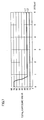
- Fig. 6 represents a relation between distance D (unit: ⁇ 10 cm) from camera 9 to an object 44 and illuminance (unit: lx) of object 44, when strobe 10 emits light, assuming that the object 44 is white and that illumination level by the natural light other than the strobe light emission does not vary on the object 44.
- the distance D is small, the illuminance of object 44 is sufficiently high, and as the distance D increases, the illuminance of object 44 decreases.
- Fig. 7 represents relations between total exposure value 31 and the distance D from camera 9 to an object 44, by a solid line Llwhen strobe 10 emits light (ON) and a dotted line L2 when strobe 10 does not emit light (OFF), assuming that the object 44 is white and that illumination level by the natural light other than strobe light emission does not vary on the object 44.
- the relations represented by the solid line L1 and the dotted line L2 of Fig. 7 hold, regardless of whether the image pick-up operation is in the close-up mode or normal mode.
- Fig. 8 represents, in the form of a table, the range of total exposure value 31 with respect to brightness of a space between camera 9 and object 44.
- the optimal brightness target brightness
- the total exposure value 31 for the image signals picked-up and output by camera 9 is in the range of 19 to 21. If it is not the optimal brightness, the total exposure value 31 is smaller than or larger than this range of 19 to 21. Therefore, here, the range of 19 to 21 is set as the optimal exposure value 141.
- Fig. 9 represents exemplary contents of the table TB mentioned previously.
- table TB shown in Fig. 9 a plurality of differences DF and quantities of light emission LM corresponding to respective differences DF are registered.
- the difference DF represents the difference between the total exposure value B that is the total exposure value 31 when strobe 10 is ON and the total exposure value C that is the total exposure value 31 when strobe 10 is OFF.
- the quantity of light emission LM represents quantity of light emission that is to be output from strobe 10 in order to have the total exposure value 31 attain to the level of the optimal exposure value 141 when the corresponding difference DF is detected.
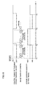
- Fig. 10 shows a sequence of ON/OFF control of strobe 10 along with time T, in accordance with the procedure of Fig. 1. The operation in accordance with the procedure of Fig. 1 will be described with reference to Fig. 10.
- mode switching lever 11 is operated and the operation mode is set either to the normal mode or the close-up mode (step (hereinafter simply represented by S) 1).
- CPU 15 reads optimal exposure value 141 from memory 14, and compares the read optimal exposure value 141 with total exposure value A (S5). When it is the case from the result of comparison that total exposure value A ⁇ optimal exposure value 141, it means that sufficient exposure value is attained without emission of strobe 10. Therefore, CPU 15 determines that image data 34 can be stored in storing unit 27, and determines whether shutter key 6 is tuned ON by the user or not (S18). When it is determined that shutter key 6 is turned ON, CPU 15 stores the image data 34 input at this time to storing unit 27 (S19). Thereafter, whether the image pick-up mode is terminated or not is determined (S20). If it is determined to be terminated (YES in S20), the series of processes is terminated (EXIT). Otherwise (NO in S20), the flow returns to the process of S3, the next image data 34 is input and the following steps are repeated in the similar manner.
- CPU 15 proceeds to (activates) the process following S6, in which the quantity of light emission is determined based on the difference between the total exposure value 31 calculated with light emission of strobe 10 and the total exposure value 31 calculated without light emission of strobe 10.
- the quantity of light emission by strobe 10 is set to the MAX value 142 (S6).
- MAX value 142 is read from memory 14, and boosting control signal 32 and ON/OFF signal 33 in accordance with the read MAX value 142 are generated and output to strobe control circuit 13. Accordingly, at timing T2 of Fig. 10, strobe 10 emits light at the level in accordance with the MAX value 142 in accordance with ON/OFF signal 33 under the control of strobe control circuit 13 (S7).
- CPU 15 receives as inputs image data 34 at this time and total exposure value 31 of the image data 34 (S8, S9).
- the total exposure value 31 input here will be total exposure value B.
- CPU 15 compares total exposure value B with optimal exposure value 141 read from memory 14 (S10). When it is determined from the result of comparison that total exposure value B ⁇ optimal exposure value 141, then whether shutter key 6 is turned ON or not is determined (S21). When it is determined that shutter key 6 is turned ON, CPU 15 stores the input image data 34 to storing unit 27 (S22). Thereafter, whether the image pick-up mode is terminated or not is determined (S23). If it is determined to be terminated (YES in S23), the series of processes is terminated (EXIT). Otherwise (NO in S23), the next image data 34 is input (S8) and the following steps are repeated in the similar manner.
- strobe 10 when strobe 10 is turned ON immediately after it is turned OFF, strobe 10 emits light with the MAX value 142, and therefore, appropriate brightness, that is, appropriate exposure level can quickly be attained when, for example, an image is to be picked-up in the dark.
- CPU 15 proceeds to the following process, in order to eliminate the state of over-exposure and to attain appropriate exposure value.
- CPU 15 stores the total exposure value B in a temporary storage area TE of memory 14 (S11), and controls (S12) strobe 10 such that emission of strobe 10 is turned OFF by boosting control signal 32 and ON/OFF control signal 33 at timing T3 of Fig. 10. Thereafter, CPU 15 receives as inputs image data 34 and total exposure value 31 of the image data 34 (S13, S14).
- the input total exposure value 31 will be total exposure value C.
- CPU 15 compares total exposure value C with the optimal exposure value 141 read from memory 14 (S15), and when it is determined from the result of comparison that total exposure value C ⁇ optimal exposure value 141, the flow returns to the process of S3 and the following processes are repeated in the similar manner.
- CPU 15 calculates a difference between the total exposure value B read from temporary storage area TE that represents the exposure when strobe 10 is turned ON with the MAX value 142 and the total exposure value C representing the exposure with strobe 10 OFF, and based on the difference, CPU 15 looks up the table TB, determines the corresponding quantity of strobe emission LM and reads the quantity (S17). Thus, the quantity of strobe emission can be determined simply by looking up the table TB.
- Boosting control signal 32 and ON/OFF signal 33 are generated and output in accordance with the strobe emission quantity LM so that strobe 10 emits light with the read strobe emission quantity LM. Therefore, at timing T4 of Fig. 10, strobe 10 emits light at the level of the emission quantity LM that corresponds to the difference DF (S7). Thereafter, the process is repeated in the similar manner.
- the light emission quantity LM of strobe 10 is determined such that total exposure value 31 matches the optimal exposure value 141, based on the difference between the total exposure value B when the strobe is ON and the total exposure value C when the strobe is OFF.
- the determination is made with reference to two values, that is, the total exposure value B when the strobe is ON and the total exposure value C when the strobe is OFF. Therefore, as compared with a determination made with reference to only one value, the light emission quantity LM that attains the optimal exposure value 141 can be determined more accurately.
- the two total exposure values B and C are relative (opposing) values that represent the total exposure values with and without emission of strobe 10, and therefore, the light emission quantity can be determined more accurately as compared with a determination using two total exposure values with emission of strobe 10 or two total exposure values without emission of strobe 10.
- the user picks-up an image of object 44 while monitoring an image on LCD 3, with the portable camera-phone PH itself held and moved by the user's hand. Therefore, at the time of image pick-up, when the operation is switched from the close-up mode to the normal mode or vice versa, and the distance between object 44 and camera 9 changes all the time, the light emission quantity of strobe 10 can be adjusted to always attain the optimal exposure value, following the variation in the distance D, as described above.
- the light emission quantity is adjusted to always attain the optimal state of exposure in the image pick-up mode, and therefore it is possible to know the operation timing of shutter key 6 from the monitor image on LCD 3. Further, whether the image is well focused or not can quickly be confirmed, and hence, it is possible for the user to switch between the close-up mode and the normal mode appropriately.
- the portable camera-phone PH shown in Fig. 3 has a function of connecting to the Internet, not shown, by communication through wireless unit 22 and antenna 21.
- URL Uniform Resource Locators
- the URL information can be obtained by CPU 15 analyzing image data 34 of a bar code as the object 44 picked-up in the close-up mode.
- optimal exposure value 141 is fixed in the present embodiment, it may be changed arbitrarily.
- a user may wish to pick-up an image of an object with not the optimal exposure level but a brighter level, or a darker level.
- the optimal exposure value 141 may variably set in accordance with the user's request.
- LEDs are used for strobe 10 in the present embodiment, other light source may be used.
- strobe 10 emits white light as red, green and blue lights are emitted simultaneously, the color of emission is not limited.
- portable camera-phone PH is not limited to the one in accordance with the present embodiment shown in Fig. 2.
- the portable device to which the function may be applied is not limited thereto.
- a digital camera using a strobe a PDA (Personal Digital Assistant) having a camera with strobe may also be possible.
Landscapes
- Engineering & Computer Science (AREA)
- Multimedia (AREA)
- Signal Processing (AREA)
- Physics & Mathematics (AREA)
- Optics & Photonics (AREA)
- Studio Devices (AREA)
- Exposure Control For Cameras (AREA)
- Stroboscope Apparatuses (AREA)
- Telephone Set Structure (AREA)
Applications Claiming Priority (2)
| Application Number | Priority Date | Filing Date | Title |
|---|---|---|---|
| JP2002215048A JP2004056713A (ja) | 2002-07-24 | 2002-07-24 | 撮影部を有した携帯機器および露出調整装置 |
| JP2002215048 | 2002-07-24 |
Publications (2)
| Publication Number | Publication Date |
|---|---|
| EP1387562A2 true EP1387562A2 (de) | 2004-02-04 |
| EP1387562A3 EP1387562A3 (de) | 2005-09-28 |
Family
ID=30112878
Family Applications (1)
| Application Number | Title | Priority Date | Filing Date |
|---|---|---|---|
| EP03016076A Ceased EP1387562A3 (de) | 2002-07-24 | 2003-07-15 | Tragbares Gerät mit belichtungsabhäniger Bildaufnahmevorrichtung und Gerät zur Einstellung der Belichtung |
Country Status (5)
| Country | Link |
|---|---|
| US (1) | US7414666B2 (de) |
| EP (1) | EP1387562A3 (de) |
| JP (1) | JP2004056713A (de) |
| CN (1) | CN1249512C (de) |
| AU (1) | AU2003213470B2 (de) |
Cited By (4)
| Publication number | Priority date | Publication date | Assignee | Title |
|---|---|---|---|---|
| WO2007140819A1 (en) * | 2006-06-09 | 2007-12-13 | Sony Ericsson Mobile Communications Ab | Mobile terminals including image sensor integrated flash sensing circuits and methods of operating the same |
| WO2008055714A1 (en) * | 2006-11-08 | 2008-05-15 | Sony Ericsson Mobile Communications Ab | Camera and method in a camera |
| WO2009100738A1 (en) * | 2008-02-14 | 2009-08-20 | Sony Ericsson Mobile Communications Ab | Method of capturing an image with a mobile device and mobile device |
| WO2018052604A1 (en) * | 2016-09-16 | 2018-03-22 | Qualcomm Incorporated | Smart camera flash system |
Families Citing this family (25)
| Publication number | Priority date | Publication date | Assignee | Title |
|---|---|---|---|---|
| US7350156B2 (en) * | 2001-09-21 | 2008-03-25 | Yamaha Corporation | Audio signal editing apparatus and control method therefor |
| AU2003902319A0 (en) | 2003-05-14 | 2003-05-29 | Garrett Thermal Systems Limited | Laser video detector |
| JP4574185B2 (ja) * | 2004-02-17 | 2010-11-04 | キヤノン株式会社 | 撮像装置及び閃光装置の制御方法 |
| KR100621007B1 (ko) * | 2004-02-19 | 2006-09-08 | 엘지전자 주식회사 | 휴대단말기의 카메라 플래쉬 장치 및 제어방법 |
| US8345120B2 (en) * | 2004-04-06 | 2013-01-01 | Nikon Corporation | Electronic camera with self-adjusting flash and image-capture sensitivity |
| CA2965635C (en) | 2004-11-12 | 2020-07-21 | Xtralis Technologies Ltd | Particle detector, system and method |
| US20060279652A1 (en) * | 2005-06-13 | 2006-12-14 | Shou-An Yang | Display panel with camera function |
| US7885690B2 (en) * | 2005-12-28 | 2011-02-08 | Toppoly Optoelectronics Corp. | Methods for driving devices capable of displaying images and processing audio messages |
| US20070260886A1 (en) * | 2006-05-02 | 2007-11-08 | Labcal Technologies Inc. | Biometric authentication device having machine-readable-zone (MRZ) reading functionality and method for implementing same |
| US7646971B2 (en) * | 2006-11-07 | 2010-01-12 | Sony Ericsson Mobile Communications Ab | Assist light illuminance control |
| US10499029B2 (en) | 2007-01-09 | 2019-12-03 | Capso Vision Inc | Methods to compensate manufacturing variations and design imperfections in a display device |
| US9007478B2 (en) * | 2007-01-09 | 2015-04-14 | Capso Vision, Inc. | Methods to compensate manufacturing variations and design imperfections in a capsule camera |
| JP5325408B2 (ja) * | 2007-10-15 | 2013-10-23 | オリンパスイメージング株式会社 | カメラ及びその制御方法 |
| TWI481846B (zh) | 2007-11-15 | 2015-04-21 | Xtralis Technologies Ltd | 在主動視頻煙霧檢測(avsd)系統中測定光束對準之技術 |
| EP2244463B1 (de) * | 2008-01-18 | 2015-10-07 | Nikon Corporation | Beleuchtunganordnung für abbildung und kamera |
| JP4883073B2 (ja) * | 2008-10-10 | 2012-02-22 | ソニー株式会社 | 動画像撮像装置および撮像方法 |
| CN101750848B (zh) * | 2008-12-11 | 2011-03-30 | 鸿富锦精密工业(深圳)有限公司 | 摄像装置及其补光方法 |
| KR101695243B1 (ko) * | 2010-02-02 | 2017-01-11 | 한화테크윈 주식회사 | 보조광 제어 장치 및 방법 |
| TWM414771U (en) * | 2011-06-10 | 2011-10-21 | Digilife Technologies Co Ltd | Real-time AV transmission device |
| KR101832372B1 (ko) * | 2011-09-02 | 2018-02-27 | 엘지전자 주식회사 | 이동 단말기 및 그 제어방법 |
| US8804029B2 (en) * | 2012-06-22 | 2014-08-12 | Microsoft Corporation | Variable flash control for improved image detection |
| JP6197412B2 (ja) * | 2013-07-01 | 2017-09-20 | 株式会社リコー | 撮像装置、画像読取装置、画像形成装置、および撮像装置の駆動方法 |
| EP3066508A4 (de) * | 2013-11-07 | 2017-08-09 | Samsung Electronics Co., Ltd. | Verfahren und system zur erzeugung eines refokussierungseffekts bei einer kamera |
| US11086198B2 (en) | 2016-01-20 | 2021-08-10 | Lumileds Llc | Driver for an adaptive light source |
| CN108989700B (zh) * | 2018-08-13 | 2020-05-15 | Oppo广东移动通信有限公司 | 成像控制方法、装置、电子设备以及计算机可读存储介质 |
Family Cites Families (29)
| Publication number | Priority date | Publication date | Assignee | Title |
|---|---|---|---|---|
| JPS5883864U (ja) | 1981-12-02 | 1983-06-07 | ヤマハ株式会社 | 調光光源装置 |
| JPS58147722A (ja) * | 1982-02-26 | 1983-09-02 | Canon Inc | カメラ |
| JPH0679128B2 (ja) | 1983-06-24 | 1994-10-05 | ミノルタカメラ株式会社 | カメラの露出制御装置 |
| US5504584A (en) * | 1991-01-30 | 1996-04-02 | Fuji Photo Film Co., Ltd. | Video movie camera capable of still photography using a stroboscopic flash |
| JP3286859B2 (ja) | 1993-01-26 | 2002-05-27 | 富士写真フイルム株式会社 | 自動調光ストロボ |
| JP3009561B2 (ja) * | 1993-04-26 | 2000-02-14 | 富士写真フイルム株式会社 | スチル・ビデオ・カメラおよびそのストロボ発光量制御データ調整装置 |
| JPH0772536A (ja) * | 1993-09-06 | 1995-03-17 | Nikon Corp | 閃光発光装置内蔵型カメラ |
| US5860029A (en) * | 1993-10-20 | 1999-01-12 | Minolta Co., Ltd. | Camera system having a flash device capable of performing a high speed synchronized photography |
| JPH0961911A (ja) | 1995-08-21 | 1997-03-07 | Canon Inc | カメラシステム |
| US6167202A (en) * | 1995-08-21 | 2000-12-26 | Canon Kabushiki Kaisha | Camera system or flash unit |
| EP0973156B1 (de) * | 1996-10-25 | 2000-12-20 | Matsushita Electric Industrial Co., Ltd. | Optische Platte mit oszillierenden Stegen und Rillen |
| US6069659A (en) * | 1997-06-03 | 2000-05-30 | Olympus Optical Co., Ltd. | Strobe device that prevents the flicker of flashlight and flashing method thereof |
| JP3926897B2 (ja) | 1997-10-09 | 2007-06-06 | オリンパス株式会社 | ストロボ装置 |
| JP3873157B2 (ja) * | 1997-11-13 | 2007-01-24 | カシオ計算機株式会社 | 電子カメラ装置および撮像方法 |
| JP2000122128A (ja) | 1998-10-16 | 2000-04-28 | Fuji Photo Film Co Ltd | カメラにおけるストロボの発光量調整方法 |
| JP4000413B2 (ja) * | 1998-11-18 | 2007-10-31 | 富士フイルム株式会社 | 電子カメラ |
| US6272292B1 (en) * | 1998-12-22 | 2001-08-07 | Nikon Corporation | Electronic flash control apparatus |
| JP4366740B2 (ja) | 1998-12-22 | 2009-11-18 | 株式会社ニコン | 閃光制御装置及びカメラ |
| JP2000267151A (ja) | 1999-03-12 | 2000-09-29 | Olympus Optical Co Ltd | カメラ |
| JP3793982B2 (ja) * | 1999-04-07 | 2006-07-05 | 富士写真フイルム株式会社 | 電子カメラ、電子カメラの指掛かり検出方法及び電子カメラのレベル変換方法 |
| GB2354832B (en) * | 1999-07-23 | 2003-05-14 | Hewlett Packard Co | Digital still camera with strobe control |
| US7345702B2 (en) * | 2000-02-07 | 2008-03-18 | Canon Kabushiki Kaisha | Image sensing apparatus, control method for illumination device, flash photographing method, and computer program product |
| JP2001230970A (ja) | 2000-02-16 | 2001-08-24 | Fuji Photo Film Co Ltd | 撮像装置 |
| US7092029B1 (en) * | 2000-03-24 | 2006-08-15 | Ess Technology, Inc. | Strobe lighting system for digital images |
| JP2001343579A (ja) | 2000-06-01 | 2001-12-14 | Canon Inc | カメラシステム |
| JP3907397B2 (ja) * | 2000-10-11 | 2007-04-18 | 富士通株式会社 | 映像監視装置 |
| JP4123327B2 (ja) * | 2000-11-28 | 2008-07-23 | 富士フイルム株式会社 | オーディオ再生機能付きカメラ |
| US6546203B2 (en) * | 2001-06-21 | 2003-04-08 | Hewlett-Packard Company | Camera with adjustable strobe energy |
| JP2003174586A (ja) * | 2001-12-07 | 2003-06-20 | Seiko Precision Inc | 撮像装置および携帯電子機器 |
-
2002
- 2002-07-24 JP JP2002215048A patent/JP2004056713A/ja active Pending
-
2003
- 2003-07-15 EP EP03016076A patent/EP1387562A3/de not_active Ceased
- 2003-07-15 AU AU2003213470A patent/AU2003213470B2/en not_active Ceased
- 2003-07-21 US US10/622,697 patent/US7414666B2/en not_active Expired - Lifetime
- 2003-07-24 CN CNB031330789A patent/CN1249512C/zh not_active Expired - Fee Related
Non-Patent Citations (1)
| Title |
|---|
| None |
Cited By (9)
| Publication number | Priority date | Publication date | Assignee | Title |
|---|---|---|---|---|
| WO2007140819A1 (en) * | 2006-06-09 | 2007-12-13 | Sony Ericsson Mobile Communications Ab | Mobile terminals including image sensor integrated flash sensing circuits and methods of operating the same |
| US7576798B2 (en) | 2006-06-09 | 2009-08-18 | Sony Ericsson Mobile Communications Ab | Mobile terminals including image sensor integrated flash sensing circuits and methods of operating the same |
| TWI422208B (zh) * | 2006-06-09 | 2014-01-01 | Sony Ericsson Mobile Comm Ab | 包含集成快閃感測電路的影像感測器之行動終端及其操作方法 |
| WO2008055714A1 (en) * | 2006-11-08 | 2008-05-15 | Sony Ericsson Mobile Communications Ab | Camera and method in a camera |
| US7697062B2 (en) | 2006-11-08 | 2010-04-13 | Sony Ericsson Mobile Communications Ab | Camera and method in a camera |
| RU2428811C2 (ru) * | 2006-11-08 | 2011-09-10 | Сони Эрикссон Мобайл Коммьюникейшнз Аб | Фотокамера и способ, выполняемый в фотокамере |
| WO2009100738A1 (en) * | 2008-02-14 | 2009-08-20 | Sony Ericsson Mobile Communications Ab | Method of capturing an image with a mobile device and mobile device |
| US8130311B2 (en) | 2008-02-14 | 2012-03-06 | Sony Ericsson Mobile Communications Ab | Method of capturing an image with a mobile device |
| WO2018052604A1 (en) * | 2016-09-16 | 2018-03-22 | Qualcomm Incorporated | Smart camera flash system |
Also Published As
| Publication number | Publication date |
|---|---|
| AU2003213470A1 (en) | 2004-02-12 |
| US20040017505A1 (en) | 2004-01-29 |
| AU2003213470B2 (en) | 2009-02-26 |
| CN1477438A (zh) | 2004-02-25 |
| JP2004056713A (ja) | 2004-02-19 |
| CN1249512C (zh) | 2006-04-05 |
| US7414666B2 (en) | 2008-08-19 |
| EP1387562A3 (de) | 2005-09-28 |
Similar Documents
| Publication | Publication Date | Title |
|---|---|---|
| US7414666B2 (en) | Portable device having exposure-adjustable image pick-up unit and exposure adjusting device | |
| US7711257B2 (en) | Image quality in cameras using flash | |
| CN100489642C (zh) | 有摄影功能的便携式装置及移动电话机 | |
| US7683967B2 (en) | Digital camera having an electronic flash device LED as a flashlight source | |
| JP4228277B2 (ja) | Led照明装置 | |
| US7847859B2 (en) | Exposure control method and imaging apparatus | |
| JP2002116481A (ja) | カメラのストロボ装置、電子カメラ及び発光ヘッド | |
| US7616874B2 (en) | Image-taking apparatus | |
| US7321395B2 (en) | Image capturing apparatus and method of setting exposure for AF control executed by image capturing apparatus | |
| JP4355500B2 (ja) | デジタルカメラ | |
| JP2003241266A (ja) | 発光装置 | |
| US7639304B2 (en) | Image pickup device and method for automatic exposure control and exposure control based on a user-set value and computer-readable storage medium having a program for controlling such a device | |
| US7542182B2 (en) | Image pickup apparatus with light emission control adapted for light-receiving characteristics | |
| KR101124243B1 (ko) | 휴대기기용 디지털 카메라 | |
| JP4662332B2 (ja) | カメラ撮影画像色調補正装置および携帯端末装置 | |
| KR100602722B1 (ko) | 플래시 광량 자동 조절 기능을 가지는 무선통신 단말기 및그 방법 | |
| KR20060014843A (ko) | 플래쉬 밝기 조절 기능을 갖는 무선통신 단말기 및 그 방법 | |
| JP3814622B2 (ja) | 撮影機能を有した携帯電話機 | |
| JPH11133476A (ja) | 撮像装置 | |
| JP2004328068A (ja) | 撮像装置及び携帯電話機 | |
| JP2005084368A (ja) | カメラ付き携帯電話機 | |
| CN100510939C (zh) | 有摄影功能的便携式装置及移动电话机 | |
| JPH10285455A (ja) | 撮影装置 | |
| JP2005062899A (ja) | 撮影機能を有した携帯機器 | |
| KR20060063331A (ko) | 휴대 단말에서 카메라 촬영을 위한 밝기 조절 장치 및 방법 |
Legal Events
| Date | Code | Title | Description |
|---|---|---|---|
| PUAI | Public reference made under article 153(3) epc to a published international application that has entered the european phase |
Free format text: ORIGINAL CODE: 0009012 |
|
| AK | Designated contracting states |
Kind code of ref document: A2 Designated state(s): AT BE BG CH CY CZ DE DK EE ES FI FR GB GR HU IE IT LI LU MC NL PT RO SE SI SK TR |
|
| AX | Request for extension of the european patent |
Extension state: AL LT LV MK |
|
| RIC1 | Information provided on ipc code assigned before grant |
Ipc: 7H 04N 5/235 B Ipc: 7G 03B 15/05 B Ipc: 7H 04N 1/028 A |
|
| PUAL | Search report despatched |
Free format text: ORIGINAL CODE: 0009013 |
|
| AK | Designated contracting states |
Kind code of ref document: A3 Designated state(s): AT BE BG CH CY CZ DE DK EE ES FI FR GB GR HU IE IT LI LU MC NL PT RO SE SI SK TR |
|
| AX | Request for extension of the european patent |
Extension state: AL LT LV MK |
|
| 17P | Request for examination filed |
Effective date: 20051221 |
|
| AKX | Designation fees paid |
Designated state(s): AT BE BG CH CY CZ DE DK EE ES FI FR GB GR HU IE IT LI LU MC NL PT RO SE SI SK TR |
|
| 17Q | First examination report despatched |
Effective date: 20060707 |
|
| STAA | Information on the status of an ep patent application or granted ep patent |
Free format text: STATUS: THE APPLICATION HAS BEEN REFUSED |
|
| 18R | Application refused |
Effective date: 20130323 |