EP1387774B2 - Luftleitkasten - Google Patents
Luftleitkasten Download PDFInfo
- Publication number
- EP1387774B2 EP1387774B2 EP02727932.2A EP02727932A EP1387774B2 EP 1387774 B2 EP1387774 B2 EP 1387774B2 EP 02727932 A EP02727932 A EP 02727932A EP 1387774 B2 EP1387774 B2 EP 1387774B2
- Authority
- EP
- European Patent Office
- Prior art keywords
- valve
- shell
- air inlet
- air
- butterfly valve
- Prior art date
- Legal status (The legal status is an assumption and is not a legal conclusion. Google has not performed a legal analysis and makes no representation as to the accuracy of the status listed.)
- Expired - Lifetime
Links
Images



Classifications
-
- B—PERFORMING OPERATIONS; TRANSPORTING
- B60—VEHICLES IN GENERAL
- B60H—ARRANGEMENTS OF HEATING, COOLING, VENTILATING OR OTHER AIR-TREATING DEVICES SPECIALLY ADAPTED FOR PASSENGER OR GOODS SPACES OF VEHICLES
- B60H1/00—Heating, cooling or ventilating devices
- B60H1/00642—Control systems or circuits; Control members or indication devices for heating, cooling or ventilating devices
- B60H1/00814—Control systems or circuits characterised by their output, for controlling particular components of the heating, cooling or ventilating installation
- B60H1/00821—Control systems or circuits characterised by their output, for controlling particular components of the heating, cooling or ventilating installation the components being ventilating, air admitting or air distributing devices
- B60H1/00835—Damper doors, e.g. position control
- B60H1/00849—Damper doors, e.g. position control for selectively commanding the induction of outside or inside air
Definitions
- the present invention generally relates to an air guiding casing and in particular to an air guiding casing which is also referred to as fresh air-to-air air box, comprising a fresh air inlet, an ambient air inlet and an air outlet.
- an ambient fresh-air valve is usually provided so that the air outlet can be connected as desired. at the fresh air inlet or the ambient air inlet.
- the document DE19748787 which constitutes the closest prior art, proposes an air guiding box with a fresh air inlet, an ambient air inlet and an air outlet, a shell valve being provided for connecting, in its extreme positions, optionally the air outlet to the fresh air inlet or to the ambient air inlet, said housing comprising at least one butterfly or butterfly valve which is actuated according to the position of the shell valve and which can rotate freely using the volume released by the shell valve and is then partially inserted into the volume in which the shell valve acts.
- the present invention therefore aims to improve an air guide housing of the type mentioned in the introduction, so that one can influence the flow of air involved in a versatile manner while maintaining a simple kinematic.
- the invention is based on the idea of combining the advantages of an air flow control by means of a shell valve and a butterfly valve, without increasing the necessary construction space at least on the side fresh air intake.
- the fresh air-to-air function and the dynamic pressure control can be realized with a simple kinematics by combining a shell valve and a butterfly valve, saving space and efficiently cooperating the respective advantageous properties of the two types of valves in a synergistic manner, which improves the overall flow characteristics and allows to influence them in an extremely varied manner.
- the axes of the shell valve and the butterfly valve are essentially parallel, these being, in a particularly preferred manner, spaced apart by at least the maximum radial dimension of the shell valve with respect to its axis. .
- the parallel axes it is possible to perform an alternating coupled activation by means of a very simple kinematics. Especially advantageous spacing ensures that the shell valve remains freely movable because it can not interact at any time with the fixed part of the butterfly valve.
- the axes of the shell valve and the butterfly valve are provided substantially perpendicular to each other. This configuration allows for example to take into account the dynamic pressure profile existing inside the housing, placing the axes in a position where the prevailing dynamic pressure is highest, so that the lever forces acting on the valve Butterfly can be handled easily.
- the butterfly valve can reduce the cross section of the outlet opening and / or the ambient air inlet opening.
- the regulation of the dynamic pressure can take place directly in front of the blower, when the butterfly valve is provided at the outlet opening, an air duct element can in this case be provided in the so-called ambient air mode.
- the butterfly valve is provided so that it can reduce the ambient air inlet opening, this makes it possible to use the shell valve selectively to perform the function of switching of fresh air to ambient air or as a valve for dynamic pressure.
- the butterfly valve is in at least one position completely in the ambient air inlet.
- the shell valve can be freely movable at least in this position of the butterfly valve.
- the shell valve can close the fresh air intake, while the butterfly valve can serve for the regulation of the ambient air flow.
- the volume in which the shell valve can be located is used to allow pivoting of the butterfly valve, especially when the shell valve is not in this part of the volume. . If, therefore, the shell valve is used in the "closed fresh air” or “dynamic pressure control” mode, the shell valve will be decisively located in the region of the inlet of the shell. fresh air, so that the region of the ambient air inlet is free and can be used to pivot the butterfly valve, to allow an addition of ambient air or also to prevent a flow in the opposite direction to the inside the outlet of the ambient air.
- the butterfly valve support and / or replace its function in the position blocking the ambient air inlet It is thus possible, through the butterfly valve, to realize the air guide housing according to the invention as if only a supply of fresh air was possible, closing the passage of ambient air.
- the shell valve may cover the butterfly valve to such an extent that the fresh air inlet is released.
- the sealing device which hermetically isolates the clamshell valve in at least one of the positions deviating from the extreme positions relative to the guide housing air.
- several lips may be provided on the outer contour of the shell valve to prevent air from passing backwards in an intermediate position of the shell valve.
- the flaps may be positioned such that dynamic pressure control and / or a partial ambient air mode can be provided.
- the figure 1 illustrates a first embodiment of an air guide housing.
- This comprises, in an upper housing portion 30, a fresh air inlet 1, an ambient air inlet 2 and an air outlet 3, which leads to a lower housing portion 40 in which one may have a blower not shown to activate the air and then push through the components of a heating and / or air conditioning system to be able to return this air by air nozzles in the inner part of the vehicle.
- a shell valve 10 is pivotally mounted about an axis 11, and has, at its ends, V-shaped sealing lips 12 in order to be able to hermetically engage in its extreme positions with portions of
- the shell valve 10 is illustrated in dashed lines in the position in which it blocks the fresh air inlet 1 and in full lines in the position in which it blocks the inlet. 2.
- the shell valve 10 may be disposed in any position between these two extreme positions.
- the butterfly valve 20 is made in an asymmetrical configuration, the two fins having an angle less than 180 °. Subsequently, the various operating modes of the illustrated air guide housing will be briefly exposed:
- the shell valve closes the fresh air inlet 1 in a sealed manner, by applying the sealing lips 11 against the wall 30 of the housing (position shown in dotted lines).
- the butterfly valve 20 can freely rotate using the volume released by the flapper With the shell 10.
- the two valves 10, 20 form a channel-shaped air duct system, which allows a better suction of the ambient air out of the interior space of the vehicle by means of the blower (not illustrated).
- the shell valve 10 In the fresh air only mode, for example for rapid ventilation of the interior space, the shell valve 10 is in a position in which it blocks the ambient air inlet 2 (position of the shell valve illustrated in lines). solid) and completely releases the fresh air inlet 1.
- the sealing lips 12 again seal against the upper portion 30 of the housing.
- the sealing function can be supported from the point of view of the fluid technique behind the closed shell valve 10 in the ambient air inlet 2 by the closed butterfly valve 20, so that even at high velocities vehicle, we can guarantee a good seal.
- the dynamic pressure caused by the vehicle speed must be regulated.
- a partial ambient air mode can also be achieved with the illustrated embodiment.
- the wing or butterfly valve 20 is open, the two valves being in a partially open position.
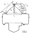
- the figure 2 illustrates an alternative embodiment with respect to the embodiment illustrated in FIG. figure 1 and which does not form part of the claimed invention, in which the same components are provided with the same reference numerals and these will not be described again in detail to the extent that they remain unchanged.
- the axes 21 extend substantially parallel to the axis 11 of the shell valve 10, the distance to the axis 11 being slightly larger than the maximum radial dimension of the shell valve 10.
- the partial ambient air can be used thus in the measurement of the partial covering of the fresh air inlet 1 by the shell valve 10 for the dynamic pressure.
- the figure 3 illustrates another embodiment of the air guide housing in a partial view with respect to the upper portion.
- the corresponding components are provided with the same reference numerals.
- the shell valve 10 can take the most diverse geometries, such as, for example, in section, the shape of an arc of a circle, a free curve, an elliptical trajectory or also a straight line. It is also possible to articulate the cylindrical valve for various possible angles of rotation on the axis 11, for example with a rotation angle of about 90 ° or also an angle of rotation higher or lower than this value.
- the butterfly valve 20 for opening the ambient air inlet 2 can no longer rotate counterclockwise but clockwise.
- the butterfly valve 20 can first utilize the space which is first released by the shell valve 10.
- the dynamic pressure applied in an intermediate position of the flapper With shell 10 pushes the butterfly valve to close, so that inadvertent backward flow into the channel behind the ambient air inlet 2 can practically be ruled out.
- the figure 4 illustrates, in a similar representation to the figure 3 , various possibilities of configuration and arrangement of the fin or butterfly valve 20 in the region of the ambient air inlet 2. It is thus illustrated the plurality of possibilities of combination of the shell valve and the finned valve or Butterfly. As can be seen, the insertion of the butterfly valve into the volume in which the shell valve 10 acts, is all the more important that the axis 21 is provided upward, with a corresponding reduction in space required in the area of the ambient air inlet 2.
- FIG 5 illustrates a representation according to the Figures 3 and 4 of an alternative embodiment, wherein the axes are no longer parallel but rather extend substantially perpendicular to each other.
- the figure 6 illustrates an air guide housing according to the invention, essentially corresponding to the embodiment illustrated in FIG. figure 3 .
- the butterfly valve is in the closed position, completely in the ambient air inlet 2.
- the operating modes are again corresponding, and in a more limited representation, the recurrent components, which are provided with the same numerical references, are not described again in detail.
- the shell valve 10 also has a plurality of injection molded sealing lips, which extend, in accordance with the conformation technique, into essentially parallel groups.
- the sealing lips which together form a sealing device 50, allow sealing engagement between the shell valve 10 and the upper housing portion 30 in a plurality of intermediate positions of the shell valve.
- the figure 7 finally illustrates an alternative embodiment of an air guide housing in which the butterfly valve is arranged not in the region of the ambient air inlet 2 but at the level of the air outlet 3 and can function as valve for dynamic pressure.
- the shell valve 10 may in turn be disposed in two extreme positions in which in each case only a fresh air mode and an ambient air mode only are possible.
- the butterfly valve 20 In the ambient air mode, the butterfly valve 20 will usually be open, to drive ambient air to the blower.
- the butterfly valve In the fresh air mode, the butterfly valve may be restrictively disposed in the air outlet 3, for example depending on the speed of the vehicle. It should be mentioned that in the embodiment illustrated here, the butterfly valve can be designed very simply because a sealing function must not be fulfilled.
- the illustrated arrangement of the two valves allows a virtually independent control for a very simple kinematics, because the axes 11, 21 are substantially perpendicular to each other and because the butterfly valve serving as a valve for the dynamic pressure, for each of its positions, is completely in the defined volume inside the shell valve.
- the regulation of the dynamic pressure can be performed by both the shell valve 10 and the butterfly valve 20.
- the off-center positioning of the butterfly valve 20 allows for configure the necessary building space in a very compact way on the air outlet side.
- the air guiding unit according to the invention makes it possible to use the advantages of the different types of valves as defined in claim 1 in a synergistic manner, so that a simple control allows a plurality different operating modes without requiring additional building space, especially in the area of fresh air intake.
Landscapes
- Physics & Mathematics (AREA)
- Thermal Sciences (AREA)
- Engineering & Computer Science (AREA)
- Mechanical Engineering (AREA)
- Lift Valve (AREA)
- Air-Flow Control Members (AREA)
- Exhaust Gas After Treatment (AREA)
- Fluid-Driven Valves (AREA)
Claims (7)
- Luftführungsgehäuse mit einem Frischlufteintritt (1), einem Umlufteintritt (2) und einem Luftaustritt (3), in welchem eine Schalenklappe (10) vorgesehen ist, die in ihren Endpositionen wahlweise den Luftaustritt (3) mit dem Frischlufteintritt (1) oder dem Umlufteintritt (2) in Verbindung setzen kann, wobei das Gehäuse mindestens eine Schmetterlingsklappe (20) umfasst, die in Abhängigkeit von der Position der Schalenklappe (10) betätigt wird, wobei die Schmetterlingsklappe (20) frei schwenken kann, indem sie ein Volumen verwendet, das von der Schalenklappe (10) freigesetzt wird, und indem sie sich dann in das Volumen einfügt, in dem die Schalenklappe (10) wirkt, wobei die mindestens eine Schmetterlingsklappe (20) den Umlufteintritt (2) in einer ihrer Endpositionen komplett verschließt, dadurch gekennzeichnet, dass die Schalenklappe (10) Dichtlippen umfasst, die zusammen eine Dichtungseinrichtung (50) bilden, was einen dichten Eingriff zwischen der Schalenklappe (10) und einem oberen Abschnitt (30) des Gehäuses in vielen Zwischenpositionen der Schmetterlingsklappe (10) gestattet.
- Luftführungsgehäuse nach Anspruch 1, dadurch gekennzeichnet, dass die Achsen (11, 21) der Schalenklappe (10) und der Schmetterlingsklappe (20) im Wesentlichen parallel vorliegen, insbesondere um mindestens die maximale radiale Abmessung der Schalenklappe (10) in Bezug auf ihre Achse (11) beabstandet.
- Luftführungsgehäuse nach Anspruch 1, dadurch gekennzeichnet, dass die Achsen (11, 21) der Schalenklappe (10) und der Schmetterlingsklappe (20) im Wesentlichen normal zueinander vorgesehen sind.
- Luftführungsgehäuse nach einem der vorhergehenden Ansprüche, dadurch gekennzeichnet, dass sich die Schmetterlingsklappe (20) in mindestens einer Position vollständig im Umlufteintritt (2) befindet.
- Luftführungsgehäuse nach einem der vorhergehenden Ansprüche, dadurch gekennzeichnet, dass die Schmetterlingsklappe (20) die Funktion der Schalenklappe (10) in der den Umlufteintritt (2) sperrenden Position unterstützt und/oder ersetzt.
- Luftführungsgehäuse nach einem der vorhergehenden Ansprüche, dadurch gekennzeichnet, dass die Dichtungseinrichtung (50) vorgesehen ist, die die Schalenklappe (10) in mindestens einer von den Endpositionen abweichenden Position in Bezug auf das Luftführungsgehäuse hermetisch abdichtet.
- Luftführungsgehäuse nach einem der vorhergehenden Ansprüche, dadurch gekennzeichnet, dass die Klappen (10, 20) derart positionierbar sind, dass eine Staudruckregelung und/oder ein Teilumluftmodus bereitgestellt sind.
Applications Claiming Priority (3)
| Application Number | Priority Date | Filing Date | Title |
|---|---|---|---|
| DE10124153 | 2001-05-17 | ||
| DE10124153A DE10124153B4 (de) | 2001-05-17 | 2001-05-17 | Luftführungsgehäuse |
| PCT/IB2002/001741 WO2002092367A1 (fr) | 2001-05-17 | 2002-05-15 | Boîtier de guidage d'air |
Publications (3)
| Publication Number | Publication Date |
|---|---|
| EP1387774A1 EP1387774A1 (de) | 2004-02-11 |
| EP1387774B1 EP1387774B1 (de) | 2009-04-22 |
| EP1387774B2 true EP1387774B2 (de) | 2013-11-13 |
Family
ID=7685207
Family Applications (1)
| Application Number | Title | Priority Date | Filing Date |
|---|---|---|---|
| EP02727932.2A Expired - Lifetime EP1387774B2 (de) | 2001-05-17 | 2002-05-15 | Luftleitkasten |
Country Status (6)
| Country | Link |
|---|---|
| EP (1) | EP1387774B2 (de) |
| AT (1) | ATE429350T1 (de) |
| DE (1) | DE10124153B4 (de) |
| ES (1) | ES2324287T3 (de) |
| MX (1) | MXPA03010457A (de) |
| WO (1) | WO2002092367A1 (de) |
Families Citing this family (10)
| Publication number | Priority date | Publication date | Assignee | Title |
|---|---|---|---|---|
| DE10339337A1 (de) * | 2003-08-25 | 2005-04-14 | Behr Gmbh & Co. Kg | Trommelklappe |
| DE102005021675A1 (de) * | 2005-05-11 | 2006-11-16 | Daimlerchrysler Ag | Belüftungsvorrichtung eines Kraftfahrzeugs |
| DE102005043502A1 (de) * | 2005-09-12 | 2007-03-15 | Behr Gmbh & Co. Kg | Ansaugmodul für eine Belüftungs-, Heizungs- oder Klimaanlage eines Fahrzeugs |
| DE102007024632A1 (de) * | 2007-05-24 | 2008-11-27 | Behr Gmbh & Co. Kg | Vorrichtung zum Steuern von Luftströmen |
| FR2934815B1 (fr) * | 2008-08-07 | 2010-09-03 | Valeo Systemes Thermiques | Boitier d'entree d'air comprenant des moyens d'attenuation de nuisances acoustiques |
| DE102008038350B4 (de) * | 2008-08-19 | 2016-05-12 | Mahle International Gmbh | Schallübertragungsvorrichtung |
| DE102008050139A1 (de) | 2008-10-04 | 2010-04-08 | Daimler Ag | Verfahren zum Vermeiden von Staulufteintragung in die Fahrgastzelle eines Kraftfahrzeugs |
| EP4045344A1 (de) | 2019-10-18 | 2022-08-24 | Highly Marelli UK Limted | Aufnahmestruktur |
| DE102021208048A1 (de) | 2021-07-27 | 2023-02-02 | Mahle International Gmbh | Ansauggehäuse |
| CN114145558B (zh) * | 2021-12-23 | 2025-03-18 | 新联电器厂有限公司 | 一种电吹风的出风组件 |
Citations (11)
| Publication number | Priority date | Publication date | Assignee | Title |
|---|---|---|---|---|
| DE19817896A1 (de) † | 1997-04-30 | 1998-11-05 | Valeo Climatisation | Luftverteilungsvorrichtung mit mehreren Klappen für Kraftfahrzeuge |
| FR2778151A1 (fr) † | 1998-04-30 | 1999-11-05 | Valeo Climatisation | Dispositif repartiteur d'un flux d'air dans un habitacle, notamment d'un vehicule automobile |
| FR2783756A1 (fr) † | 1998-09-30 | 2000-03-31 | Valeo Climatisation | Dispositif de chauffage-ventilation et/ou climatisation avec isolement du circuit d'air de l'exterieur |
| DE19957858A1 (de) † | 1998-12-01 | 2000-06-08 | Valeo Climatisation | Kraftfahrzeugheiz- und/oder Klimaanlage mit kompakter Motor-Ventilatoranordnung |
| DE10025334A1 (de) † | 1999-05-28 | 2000-11-30 | Valeo Climatisation | Luftverteiler einer Heiz-, Lüftungs- und/oder Klimaanlage |
| DE19926389A1 (de) † | 1999-06-10 | 2000-12-14 | Behr Gmbh & Co | Luftführungsanordnung für eine Kraftfahrzeug-Klimatisierungsanlage |
| JP2001071735A (ja) † | 1999-09-08 | 2001-03-21 | Denso Corp | 車両用空調装置 |
| US6319112B2 (en) † | 1999-12-07 | 2001-11-20 | Behr Gmbh & Co. | Air flap for a ventilation, heating or air conditioning system of a motor vehicle |
| EP1500532A1 (de) † | 2003-07-25 | 2005-01-26 | Delphi Technologies, Inc. | Klimatisierungsmodul |
| DE102005048910A1 (de) † | 2005-10-11 | 2007-04-12 | Behr Gmbh & Co. Kg | Regelvorrichtung für ein Kraftfahrzeug und Verfahren zur Regelung |
| DE102009009912A1 (de) † | 2008-03-03 | 2009-09-10 | DENSO CORPORATION, Kariya-shi | Innen-/Außenluftumschaltvorrichtung eines Fahrzeugklimatisierungssystems |
Family Cites Families (6)
| Publication number | Priority date | Publication date | Assignee | Title |
|---|---|---|---|---|
| DE4228866C2 (de) * | 1992-08-29 | 1999-03-18 | Behr Gmbh & Co | Absperrvorrichtung, insbesondere für eine Heizungs- oder Klimaanlage eines Kraftfahrzeugs |
| DE4414036A1 (de) * | 1994-04-22 | 1995-10-26 | Behr Gmbh & Co | Lufteintritt für eine Heizungs- oder Klimaanlage eines Kraftfahrzeugs |
| US5876277A (en) * | 1997-02-04 | 1999-03-02 | Denso Corporation | Air conditioning apparatus for vehicle, having deodorizing filter |
| DE19733052B4 (de) * | 1997-07-31 | 2006-06-08 | Behr Gmbh & Co. Kg | Lufteintritt für eine Heizungs- oder Klimaanlage eines Kraftfahrzeuges |
| DE19748787B4 (de) * | 1997-11-05 | 2006-06-08 | Behr Gmbh & Co. Kg | Lufteinlaßvorrichtung für eine Lüftungs-, Heizungs- oder Klimaanlage eines Kraftfahrzeugs |
| FR2788086B1 (fr) * | 1998-12-30 | 2001-02-09 | Valeo Climatisation | Dispositif de chauffage, ventilation et/ou climatisation comportant un pulseur d'aspiration |
-
2001
- 2001-05-17 DE DE10124153A patent/DE10124153B4/de not_active Expired - Lifetime
-
2002
- 2002-05-15 WO PCT/IB2002/001741 patent/WO2002092367A1/fr not_active Ceased
- 2002-05-15 ES ES02727932T patent/ES2324287T3/es not_active Expired - Lifetime
- 2002-05-15 AT AT02727932T patent/ATE429350T1/de not_active IP Right Cessation
- 2002-05-15 EP EP02727932.2A patent/EP1387774B2/de not_active Expired - Lifetime
- 2002-05-15 MX MXPA03010457A patent/MXPA03010457A/es active IP Right Grant
Patent Citations (11)
| Publication number | Priority date | Publication date | Assignee | Title |
|---|---|---|---|---|
| DE19817896A1 (de) † | 1997-04-30 | 1998-11-05 | Valeo Climatisation | Luftverteilungsvorrichtung mit mehreren Klappen für Kraftfahrzeuge |
| FR2778151A1 (fr) † | 1998-04-30 | 1999-11-05 | Valeo Climatisation | Dispositif repartiteur d'un flux d'air dans un habitacle, notamment d'un vehicule automobile |
| FR2783756A1 (fr) † | 1998-09-30 | 2000-03-31 | Valeo Climatisation | Dispositif de chauffage-ventilation et/ou climatisation avec isolement du circuit d'air de l'exterieur |
| DE19957858A1 (de) † | 1998-12-01 | 2000-06-08 | Valeo Climatisation | Kraftfahrzeugheiz- und/oder Klimaanlage mit kompakter Motor-Ventilatoranordnung |
| DE10025334A1 (de) † | 1999-05-28 | 2000-11-30 | Valeo Climatisation | Luftverteiler einer Heiz-, Lüftungs- und/oder Klimaanlage |
| DE19926389A1 (de) † | 1999-06-10 | 2000-12-14 | Behr Gmbh & Co | Luftführungsanordnung für eine Kraftfahrzeug-Klimatisierungsanlage |
| JP2001071735A (ja) † | 1999-09-08 | 2001-03-21 | Denso Corp | 車両用空調装置 |
| US6319112B2 (en) † | 1999-12-07 | 2001-11-20 | Behr Gmbh & Co. | Air flap for a ventilation, heating or air conditioning system of a motor vehicle |
| EP1500532A1 (de) † | 2003-07-25 | 2005-01-26 | Delphi Technologies, Inc. | Klimatisierungsmodul |
| DE102005048910A1 (de) † | 2005-10-11 | 2007-04-12 | Behr Gmbh & Co. Kg | Regelvorrichtung für ein Kraftfahrzeug und Verfahren zur Regelung |
| DE102009009912A1 (de) † | 2008-03-03 | 2009-09-10 | DENSO CORPORATION, Kariya-shi | Innen-/Außenluftumschaltvorrichtung eines Fahrzeugklimatisierungssystems |
Also Published As
| Publication number | Publication date |
|---|---|
| WO2002092367A1 (fr) | 2002-11-21 |
| MXPA03010457A (es) | 2004-03-09 |
| DE10124153B4 (de) | 2010-08-05 |
| EP1387774B1 (de) | 2009-04-22 |
| ES2324287T3 (es) | 2009-08-04 |
| ATE429350T1 (de) | 2009-05-15 |
| DE10124153A1 (de) | 2002-11-21 |
| EP1387774A1 (de) | 2004-02-11 |
Similar Documents
| Publication | Publication Date | Title |
|---|---|---|
| EP1387774B2 (de) | Luftleitkasten | |
| FR3092650A1 (fr) | Event à élément aérodynamique pour réguler un flux d’air | |
| FR2894315A1 (fr) | Vanne comportant des moyens d'actionnement entre deux conduits de sortie. | |
| EP2889168B1 (de) | Vorrichtung zum Heizen, Belüften und/oder Klimatisieren | |
| FR2871413A1 (fr) | Systeme de commande de refroidissement/climatisation combine pour vehicules a moteur | |
| FR3009362A1 (fr) | Ensemble a vanne et installation de gaz d'echappement | |
| EP1514707B1 (de) | Verbesserte Lufttemperatursteuerung einer Heiz- und/oder Klimaanlage einer Fahrgastzelle | |
| FR3045741A1 (fr) | Pulseur d'aspiration destine a un dispositif de chauffage, ventilation et/ou climatisation d'un vehicule automobile et dispositif de chauffage, ventilation et/ou climatisation | |
| EP0709241A1 (de) | Heizungs- und/oder Belüftungsanlage eines Fahrzeuginnenraumes | |
| EP1242258B1 (de) | Luftleitkasten | |
| EP3702189A1 (de) | Belüftungsvorrichtung für fahrzeug | |
| EP1473449B1 (de) | Vorrichtung zur Steuerung des Luftstromes für ein Kühlmodul eines Kraftfahrzeugs | |
| FR3083164A1 (fr) | Aerateur a effet coanda pour vehicule automobile | |
| FR2947319A1 (fr) | Vanne a boisseau, boisseau pour une telle vanne et circuit d'admission de gaz dans un moteur thermique de vehicule avec une telle vanne | |
| WO2020174146A1 (fr) | Installation de chauffage et/ou ventilation et/ou climatisation comportant un volet de mixage avec déflecteur | |
| FR3064542A1 (fr) | Systeme de gestion d'entree d'air pour face avant de vehicule automobile | |
| EP1514708B1 (de) | Heiz und/oder Klimatiserungsvorrichtung für Fahrzeuginnenraum, mit hoch entwickelter aerothermischer Regelung | |
| EP1556659B1 (de) | Wärmetauscher mit durchflussregelung, insbesondere für kraftfahrzeuge | |
| FR2862255A1 (fr) | Dispositif de chauffage, ventilation et conditionnement d'air de vehicules | |
| FR2746714A1 (fr) | Dispositif de chauffage et/ou climatisation de l'habitacle d'un vehicule automobile | |
| FR2914978A1 (fr) | Vanne quatre voies a obturation simultanee de deux voies | |
| FR3032154A1 (fr) | Dispositif de sortie d'air d'un systeme d'aeration pour vehicule | |
| FR2816360A1 (fr) | Element de canalisation d'un flux d'air, bloc avant et vehicule automobile correspondants | |
| FR2826912A1 (fr) | Installation de chauffage d'habitacle de vehicule automobile | |
| EP2850349A1 (de) | Flüssigkeitsumlaufventil |
Legal Events
| Date | Code | Title | Description |
|---|---|---|---|
| PUAI | Public reference made under article 153(3) epc to a published international application that has entered the european phase |
Free format text: ORIGINAL CODE: 0009012 |
|
| 17P | Request for examination filed |
Effective date: 20031113 |
|
| AK | Designated contracting states |
Kind code of ref document: A1 Designated state(s): AT BE CH CY DE DK ES FI FR GB GR IE IT LI LU MC NL PT SE TR |
|
| 17Q | First examination report despatched |
Effective date: 20070703 |
|
| GRAP | Despatch of communication of intention to grant a patent |
Free format text: ORIGINAL CODE: EPIDOSNIGR1 |
|
| GRAS | Grant fee paid |
Free format text: ORIGINAL CODE: EPIDOSNIGR3 |
|
| GRAA | (expected) grant |
Free format text: ORIGINAL CODE: 0009210 |
|
| RBV | Designated contracting states (corrected) |
Designated state(s): AT BE CH CY DK ES FI FR GB GR IE IT LI LU MC NL PT SE TR |
|
| RBV | Designated contracting states (corrected) |
Designated state(s): AT BE CH CY DK ES FI FR GB GR IE IT LI LU MC NL PT SE TR |
|
| AK | Designated contracting states |
Kind code of ref document: B1 Designated state(s): AT BE CH CY DK ES FI FR GB GR IE IT LI LU MC NL PT SE TR |
|
| REG | Reference to a national code |
Ref country code: GB Ref legal event code: FG4D Free format text: NOT ENGLISH |
|
| REG | Reference to a national code |
Ref country code: CH Ref legal event code: EP |
|
| REG | Reference to a national code |
Ref country code: IE Ref legal event code: FG4D |
|
| REG | Reference to a national code |
Ref country code: DE Ref legal event code: 8566 |
|
| REG | Reference to a national code |
Ref country code: ES Ref legal event code: FG2A Ref document number: 2324287 Country of ref document: ES Kind code of ref document: T3 |
|
| NLV1 | Nl: lapsed or annulled due to failure to fulfill the requirements of art. 29p and 29m of the patents act | ||
| PG25 | Lapsed in a contracting state [announced via postgrant information from national office to epo] |
Ref country code: PT Free format text: LAPSE BECAUSE OF FAILURE TO SUBMIT A TRANSLATION OF THE DESCRIPTION OR TO PAY THE FEE WITHIN THE PRESCRIBED TIME-LIMIT Effective date: 20090822 Ref country code: FI Free format text: LAPSE BECAUSE OF FAILURE TO SUBMIT A TRANSLATION OF THE DESCRIPTION OR TO PAY THE FEE WITHIN THE PRESCRIBED TIME-LIMIT Effective date: 20090422 Ref country code: AT Free format text: LAPSE BECAUSE OF FAILURE TO SUBMIT A TRANSLATION OF THE DESCRIPTION OR TO PAY THE FEE WITHIN THE PRESCRIBED TIME-LIMIT Effective date: 20090422 |
|
| BERE | Be: lapsed |
Owner name: VALEO KLIMASYSTEME G.M.B.H. Effective date: 20090531 |
|
| PG25 | Lapsed in a contracting state [announced via postgrant information from national office to epo] |
Ref country code: SE Free format text: LAPSE BECAUSE OF FAILURE TO SUBMIT A TRANSLATION OF THE DESCRIPTION OR TO PAY THE FEE WITHIN THE PRESCRIBED TIME-LIMIT Effective date: 20090722 Ref country code: NL Free format text: LAPSE BECAUSE OF FAILURE TO SUBMIT A TRANSLATION OF THE DESCRIPTION OR TO PAY THE FEE WITHIN THE PRESCRIBED TIME-LIMIT Effective date: 20090422 |
|
| REG | Reference to a national code |
Ref country code: IE Ref legal event code: FD4D |
|
| PG25 | Lapsed in a contracting state [announced via postgrant information from national office to epo] |
Ref country code: MC Free format text: LAPSE BECAUSE OF NON-PAYMENT OF DUE FEES Effective date: 20090531 |
|
| REG | Reference to a national code |
Ref country code: CH Ref legal event code: PL |
|
| PG25 | Lapsed in a contracting state [announced via postgrant information from national office to epo] |
Ref country code: LI Free format text: LAPSE BECAUSE OF NON-PAYMENT OF DUE FEES Effective date: 20090531 Ref country code: IE Free format text: LAPSE BECAUSE OF FAILURE TO SUBMIT A TRANSLATION OF THE DESCRIPTION OR TO PAY THE FEE WITHIN THE PRESCRIBED TIME-LIMIT Effective date: 20090422 Ref country code: DK Free format text: LAPSE BECAUSE OF FAILURE TO SUBMIT A TRANSLATION OF THE DESCRIPTION OR TO PAY THE FEE WITHIN THE PRESCRIBED TIME-LIMIT Effective date: 20090422 Ref country code: CH Free format text: LAPSE BECAUSE OF NON-PAYMENT OF DUE FEES Effective date: 20090531 |
|
| PLBI | Opposition filed |
Free format text: ORIGINAL CODE: 0009260 |
|
| PLAX | Notice of opposition and request to file observation + time limit sent |
Free format text: ORIGINAL CODE: EPIDOSNOBS2 |
|
| 26 | Opposition filed |
Opponent name: BEHR GMBH & CO. KG Effective date: 20100122 |
|
| GBPC | Gb: european patent ceased through non-payment of renewal fee |
Effective date: 20090722 |
|
| PG25 | Lapsed in a contracting state [announced via postgrant information from national office to epo] |
Ref country code: GB Free format text: LAPSE BECAUSE OF NON-PAYMENT OF DUE FEES Effective date: 20090722 |
|
| PLAB | Opposition data, opponent's data or that of the opponent's representative modified |
Free format text: ORIGINAL CODE: 0009299OPPO |
|
| PG25 | Lapsed in a contracting state [announced via postgrant information from national office to epo] |
Ref country code: BE Free format text: LAPSE BECAUSE OF NON-PAYMENT OF DUE FEES Effective date: 20090531 |
|
| PLAF | Information modified related to communication of a notice of opposition and request to file observations + time limit |
Free format text: ORIGINAL CODE: EPIDOSCOBS2 |
|
| R26 | Opposition filed (corrected) |
Opponent name: BEHR GMBH & CO. KG Effective date: 20100122 |
|
| PG25 | Lapsed in a contracting state [announced via postgrant information from national office to epo] |
Ref country code: GR Free format text: LAPSE BECAUSE OF FAILURE TO SUBMIT A TRANSLATION OF THE DESCRIPTION OR TO PAY THE FEE WITHIN THE PRESCRIBED TIME-LIMIT Effective date: 20090723 |
|
| PLBB | Reply of patent proprietor to notice(s) of opposition received |
Free format text: ORIGINAL CODE: EPIDOSNOBS3 |
|
| PG25 | Lapsed in a contracting state [announced via postgrant information from national office to epo] |
Ref country code: LU Free format text: LAPSE BECAUSE OF NON-PAYMENT OF DUE FEES Effective date: 20090515 |
|
| PG25 | Lapsed in a contracting state [announced via postgrant information from national office to epo] |
Ref country code: TR Free format text: LAPSE BECAUSE OF FAILURE TO SUBMIT A TRANSLATION OF THE DESCRIPTION OR TO PAY THE FEE WITHIN THE PRESCRIBED TIME-LIMIT Effective date: 20090422 |
|
| PG25 | Lapsed in a contracting state [announced via postgrant information from national office to epo] |
Ref country code: CY Free format text: LAPSE BECAUSE OF FAILURE TO SUBMIT A TRANSLATION OF THE DESCRIPTION OR TO PAY THE FEE WITHIN THE PRESCRIBED TIME-LIMIT Effective date: 20090422 |
|
| PLAB | Opposition data, opponent's data or that of the opponent's representative modified |
Free format text: ORIGINAL CODE: 0009299OPPO |
|
| R26 | Opposition filed (corrected) |
Opponent name: BEHR GMBH & CO. KG Effective date: 20100122 |
|
| PGFP | Annual fee paid to national office [announced via postgrant information from national office to epo] |
Ref country code: ES Payment date: 20120524 Year of fee payment: 11 |
|
| APBM | Appeal reference recorded |
Free format text: ORIGINAL CODE: EPIDOSNREFNO |
|
| APBP | Date of receipt of notice of appeal recorded |
Free format text: ORIGINAL CODE: EPIDOSNNOA2O |
|
| APAH | Appeal reference modified |
Free format text: ORIGINAL CODE: EPIDOSCREFNO |
|
| APBU | Appeal procedure closed |
Free format text: ORIGINAL CODE: EPIDOSNNOA9O |
|
| PUAH | Patent maintained in amended form |
Free format text: ORIGINAL CODE: 0009272 |
|
| STAA | Information on the status of an ep patent application or granted ep patent |
Free format text: STATUS: PATENT MAINTAINED AS AMENDED |
|
| 27A | Patent maintained in amended form |
Effective date: 20131113 |
|
| AK | Designated contracting states |
Kind code of ref document: B2 Designated state(s): AT BE CH CY DK ES FI FR GB GR IE IT LI LU MC NL PT SE TR |
|
| PG25 | Lapsed in a contracting state [announced via postgrant information from national office to epo] |
Ref country code: ES Free format text: LAPSE BECAUSE OF FAILURE TO SUBMIT A TRANSLATION OF THE DESCRIPTION OR TO PAY THE FEE WITHIN THE PRESCRIBED TIME-LIMIT Effective date: 20131113 |
|
| REG | Reference to a national code |
Ref country code: FR Ref legal event code: PLFP Year of fee payment: 15 |
|
| REG | Reference to a national code |
Ref country code: FR Ref legal event code: PLFP Year of fee payment: 16 |
|
| REG | Reference to a national code |
Ref country code: FR Ref legal event code: PLFP Year of fee payment: 17 |
|
| PGFP | Annual fee paid to national office [announced via postgrant information from national office to epo] |
Ref country code: FR Payment date: 20210531 Year of fee payment: 20 Ref country code: IT Payment date: 20210512 Year of fee payment: 20 |
|
| P01 | Opt-out of the competence of the unified patent court (upc) registered |
Effective date: 20230629 |