EP1388446A2 - Garniture intérieure pour carosserie de véhicule - Google Patents
Garniture intérieure pour carosserie de véhicule Download PDFInfo
- Publication number
- EP1388446A2 EP1388446A2 EP03016743A EP03016743A EP1388446A2 EP 1388446 A2 EP1388446 A2 EP 1388446A2 EP 03016743 A EP03016743 A EP 03016743A EP 03016743 A EP03016743 A EP 03016743A EP 1388446 A2 EP1388446 A2 EP 1388446A2
- Authority
- EP
- European Patent Office
- Prior art keywords
- inner shell
- flap
- use position
- shell
- bearing
- Prior art date
- Legal status (The legal status is an assumption and is not a legal conclusion. Google has not performed a legal analysis and makes no representation as to the accuracy of the status listed.)
- Withdrawn
Links
- 230000033001 locomotion Effects 0.000 claims description 16
- 239000006260 foam Substances 0.000 claims description 12
- 239000004033 plastic Substances 0.000 claims description 10
- 229920003023 plastic Polymers 0.000 claims description 10
- 239000012925 reference material Substances 0.000 claims description 7
- 230000000295 complement effect Effects 0.000 claims description 3
- 230000000694 effects Effects 0.000 claims description 2
- 230000036316 preload Effects 0.000 claims description 2
- 239000004744 fabric Substances 0.000 description 9
- 239000000853 adhesive Substances 0.000 description 5
- 230000001070 adhesive effect Effects 0.000 description 5
- 238000007789 sealing Methods 0.000 description 5
- 239000011324 bead Substances 0.000 description 4
- 229910052751 metal Inorganic materials 0.000 description 4
- 239000002184 metal Substances 0.000 description 4
- 238000005187 foaming Methods 0.000 description 3
- 238000004519 manufacturing process Methods 0.000 description 3
- 230000004397 blinking Effects 0.000 description 2
- 239000010985 leather Substances 0.000 description 2
- 239000000463 material Substances 0.000 description 2
- 239000002985 plastic film Substances 0.000 description 2
- 229920006255 plastic film Polymers 0.000 description 2
- 238000004026 adhesive bonding Methods 0.000 description 1
- 229910052782 aluminium Inorganic materials 0.000 description 1
- XAGFODPZIPBFFR-UHFFFAOYSA-N aluminium Chemical compound [Al] XAGFODPZIPBFFR-UHFFFAOYSA-N 0.000 description 1
- 230000009286 beneficial effect Effects 0.000 description 1
- 230000001447 compensatory effect Effects 0.000 description 1
- 239000002131 composite material Substances 0.000 description 1
- 238000005520 cutting process Methods 0.000 description 1
- 238000011161 development Methods 0.000 description 1
- 230000018109 developmental process Effects 0.000 description 1
- 238000005516 engineering process Methods 0.000 description 1
- 230000002349 favourable effect Effects 0.000 description 1
- 239000002657 fibrous material Substances 0.000 description 1
- 239000003365 glass fiber Substances 0.000 description 1
- 238000009434 installation Methods 0.000 description 1
- 230000002787 reinforcement Effects 0.000 description 1
- 230000000284 resting effect Effects 0.000 description 1
- 238000009958 sewing Methods 0.000 description 1
- 238000007493 shaping process Methods 0.000 description 1
- 238000004904 shortening Methods 0.000 description 1
- 239000004753 textile Substances 0.000 description 1
Images


Classifications
-
- B—PERFORMING OPERATIONS; TRANSPORTING
- B60—VEHICLES IN GENERAL
- B60R—VEHICLES, VEHICLE FITTINGS, OR VEHICLE PARTS, NOT OTHERWISE PROVIDED FOR
- B60R13/00—Elements for body-finishing, identifying, or decorating; Arrangements or adaptations for advertising purposes
- B60R13/02—Internal Trim mouldings ; Internal Ledges; Wall liners for passenger compartments; Roof liners
- B60R13/0212—Roof or head liners
-
- B—PERFORMING OPERATIONS; TRANSPORTING
- B60—VEHICLES IN GENERAL
- B60R—VEHICLES, VEHICLE FITTINGS, OR VEHICLE PARTS, NOT OTHERWISE PROVIDED FOR
- B60R13/00—Elements for body-finishing, identifying, or decorating; Arrangements or adaptations for advertising purposes
- B60R13/02—Internal Trim mouldings ; Internal Ledges; Wall liners for passenger compartments; Roof liners
- B60R13/0275—Internal Trim mouldings ; Internal Ledges; Wall liners for passenger compartments; Roof liners comprising removable or hinged parts
Definitions
- the present invention relates to an inner shell or an interior trim part for vehicle bodies accordingly the preamble of claim 1.
- the invention relates to a vehicle roof module, the inner shell assigned at least one flap serving as a sun visor is.
- Such prefabricated vehicle roofs ready for installation are finished separately from the vehicle body and only on the assembly line in the automobile factory with the vehicle body united. Especially because of the considerable shortening Such vehicle roof modules gain the assembly time on the assembly line increasingly important in mass production.
- a vehicle roof module whose inner shell at least one as a sun visor serving flap is assigned are according to the invention trained inner shells basically for all surface areas of vehicle bodies, including hoods, doors and flaps / lids, and regardless of whether the each area now around a fixed body component or a module part, suitable, on the inside a flap-like element is provided, which is optional can be opened or closed, for example, to access Allow functional elements on the respective part where fasteners, locks, drive elements, such as electric motors, gears or cables for window regulators, electrical components, e.g.
- Lamps, antennas or loudspeakers, or the like functional elements can act.
- flaps optionally close cavities, such as the Serve inclusion of sunglasses, garage door openers, etc. insofar is a vehicle roof module with a sun visor arrangement to be precise about the place of application described or case of the invention, but without restrictive meaning.
- the invention has for its object an inner shell for vehicle bodies, the at least one optional movable between a non-use position and a use position Flap is assigned to develop such that the Flap arrangement is designed to save space.
- the valve is not in its non-use position or at most only very slightly over the inner shell in Thickness direction before, so that they are particularly in their use as a sun visor on a vehicle roof or module of the driver is not additionally restricted and furthermore the Vehicle interior with a view to maximum headroom can be optimized for the driver or passengers. Also is a visually appealing by the measures according to the invention outer appearance of the inner shell achieved because the flaps to be provided on the inner shell for functional reasons in their non-use position for the vehicle occupants visible surface of the inner shell not in terms of design undesirably "fissured".
- the flap as Part of the inner shell is formed, the overall structure is simplified, being a part that is used to form the interior trim of the vehicle is to be provided anyway, namely the inner shell, at least one additional function is assigned. Not least in terms of the total weight of the corresponding Body part is the solution according to the invention as advantageous to evaluate: The fact that the flap as part of the Inner shell is designed for the flap as such no additional part that increases the total weight, such as conventional sun visor arrangements.
- the flap is useful connected at one edge to the inner shell via a hinge. If the hinge lies in the direction of travel of the vehicle in front of the flap serving as a sun visor, as in the claim 3 indicated, this has the advantage that if the Driver opens the flap for shading the vehicle interior swings down when not in use, the flap Blinking angle continuously narrowed.
- the hinge in Driving direction of the vehicle seen behind the as a sun visor serving flap it occurs during the pivoting movement of the Flap from their non-use position to their use position at short notice in addition to restricting headroom also an extreme narrowing of the viewing angle during which it is for it is difficult for the driver to observe the traffic situation, which can lead to dangerous situations.
- Claim 4 also sees a manufacturing technology here Favorable embodiment that the flap in one piece is formed with the inner shell, the hinge in advantageously simple by a reduced in thickness Section of the inner shell is formed.
- the flap points to the Hinge edge adjoining side edges that in the non-use position the flap from adjacent edges of the inner shell are separated by parting lines, which are advantageous just get trained. It is basically possible that the joints in a central area of the inner shell, i.e. formed from the edge of the inner shell in its surface become. Technically simpler and at least in this respect however, it is preferred if, as in claim 6 specified, the parting lines starting from one end of the Inner shell, i.e. from its edge to the inside of the inner shell extend.
- a guide device provided for the pivoting movement of the flap, which is complementary interlocking circular arc sections which provide guidance has, which with respect to a pivot axis of Flap are centered.
- a management facility on the one hand ensures a good feeling of activity when the Flap is swung out of its non-use position because the flap is not only held over the hinge.
- the Flap also in intermediate positions between their non-use position and let go of their position of use without the flap due to its own weight from this intermediate position moved away.
- a circular arc section through a foamed bearing shell formed during the other arc section through one of the flap adjacent the inner shell is foamed bearing shell, wherein one of the bearing shells has an arcuate slot, which has an arcuate end of the other bearing shell slidably accommodates.
- a holding device for releasably fixing the flap in its non-use position and / or their position of use may be provided with one assigned to the non-use position or use position, with respect to a non-movable part of the inner shell Locking groove, into the locking lug assigned to the flap can be snapped into place.
- Such a holding device can each According to requirements for an additional fixation the flap in their respective end position, so that about a relatively long flap when the motor vehicle is in motion tends to vibrate rather than accidentally can move away from their respective end position.
- the locking grooves on circular arc-shaped slot of one bearing shell, while the latch at the circular end of the other Bearing shell is formed.
- the flap is by means of biased at least one spring element into the non-use position, that instead of or in addition to that mentioned above Guide or holding device may be provided can.
- the spring element is on the one hand a good feeling of operation beneficial when swinging the flap down or out, because the spring element for a defined actuation resistance provides.
- When swiveling the Flap supports the spring element in an advantageous manner Operator during the swivel movement.
- that ensures Spring element for a defined end position of the flap in the Non-use position, from which the flap is due to the spring preload also not automatically or in unintentional Way can move away.
- advantageous Further spring devices are two spring elements provided, each on one of the flexible side wall sections attack, the spring elements the side wall sections and thus the flap indirectly in the non-use position Pretension.
- the spring elements here in advantageously also for the flexible side wall sections assume a defined end position when the Flap is in its non-use position.
- the spring elements pull when the flap moves the flexible from the use position to the non-use position.
- Sidewall sections from the parting lines between the side edges the flap and the adjacent edges of the inner shell away so that the side wall sections are not in the parting lines can be damaged or there the pivoting movement of the Can hinder flap.
- Claim 17 provides that in one piece with the flap a recessed grip is formed on which the operator can attack can to the flap from the non-use position in the Use position or vice versa to move. As a result of the one-piece There is no need to form the recessed grip with the flap here other parts such as handle scales and the associated additional assembly steps.
- the figures show one molded from a foam plastic Inner shell 10 for a vehicle roof module 12 as an example for a module part on vehicle bodies, the inner shell 10 at least one, two in the illustrated embodiment Flaps 14 are assigned, which can be selected from one of the 1, 3, 4 and 6 non-use position shown in a in the Fig. 2 and 5 use position shown and vice versa can be moved.
- the flaps 14 are used in the illustrated embodiment as sun visors, but instead or in addition also access to a functional element (not shown) and / or allow a cavity 16 of the vehicle roof module 12. It is essential that the flaps 14 as part of the inner shell 10 are formed and in their non-use position in essentially flush with the flap Complete 14 adjacent areas of the inner shell 10, such as 1, 4 and 6 in particular.
- the vehicle roof module 12 also includes the inner shell 10 with the flaps 14 etc. a centrally located Interior light 18, which is embedded in the inner shell 10 and is essentially flush with it, as well as handles 20 arranged on each of its two sides, which are in easily accessible locations for vehicle occupants are located.
- the vehicle roof module 12 is in the Figures in an already mounted on the body frame of the vehicle Condition shown, the windshield of the vehicle 22, the A-pillar 24 and a side window 26 in the 1 to 3 can be seen.
- a front cross member of the body frame is designated 28 in Figs. 4 to 6.
- the inner shell 10 of the vehicle roof module 12 is made a foam plastic molded in the embodiment shown is foamed onto a rigid roof skin 30.
- the rigid roof skin 30 consists of a deep-drawn metal sheet, for example aluminum sheet, or can be formed from a vacuum-formed plastic film his. 4 and 5 also show that the inner shell 10 in Area of the intended for resting on the body frame Outer edges of the vehicle roof module 12 in two layers 32, 34 is divided, of which the upper layer 32 on the body frame is applied, while the lower layer 34 in one piece is formed with the flaps 14, as described in more detail will also be used to cover the body frame serves. It was mentioned at the beginning that the Inner shell 10 basically also separately from the respective body part produced and then subsequently with the help of suitable Fasteners on the respective body part if necessary can also be detachably attached.
- Suitable materials for the inner shell 10 are rigid foam plastics based on PUR, which is protected by the plastic in front of the Foaming incorporated fiber materials, for example glass fiber sections, can be armored. But also in the foam form inlaid fabrics, knitted fabrics, fleeces and the like are used as reinforcement suitable.
- the upper layer 32 according to FIGS. 4 and 5 up to an edge fold 36 of the roof skin 30 is sufficient sandwich-like composite roof module with high dimensional stability and Strength. All contours of the inner shell 10 including the lower layer 34 and its profiles are made by appropriate Shaping the foam mold (not shown) is formed.
- the inner surface of the inner shell facing the vehicle interior 10 is in the illustrated embodiment for training a headliner coated with a reference material 38, which is flexible enough to fit the inside surface of the Adapt inner shell 10.
- a reference material 38 which is flexible enough to fit the inside surface of the Adapt inner shell 10.
- the reference material 38 can be made of a textile fabric, Leather, an imitation leather or suede or a decorative plastic film, depending on the respective Design requirements.
- FIGS. 4 and 5 In the area of the support on the body frame is the upper one Layer 32 of the inner shell 10 with circumferentially molded receiving grooves 40 in which the vehicle roof module 12 against the body frame, in FIGS. 4 and 5 only schematically shown adhesive beads 42 added are, which also the attachment of the vehicle roof module 12 on Body frames serve.
- adhesive beads 42 added are, which also the attachment of the vehicle roof module 12 on Body frames serve.
- Mounting screws 44 which are assigned mounting holes in the front transverse part 28 of the body frame of reach through at the bottom and are screwed into threaded holes, the metal profile foamed in one of the upper layer 32 46 are formed. From Fig. 5 it can be seen that the mounting screws 44 easily accessible from the vehicle interior are when the flaps 14 are in their position of use.
- an elastomeric sealing profile 48 which has a projecting outer lip 50 sealingly abuts the outer surface of the roof skin 30 while sealing a projecting inner lip 52 of the sealing profile 48 the edge fold 36 of the roof skin 30 rests.
- an outwardly projecting Flange of the front cross member 28 of the body frame takes over another bead of adhesive 54 the attachment and sealing the windshield 22 on or opposite the vehicle body.
- Parting lines 66 Cut. Also starting from the free end of the inner shell 10 or lower layer 34 extending to the hinge 58 Parting lines 66 can easily be made by suitable Form protrusions in the foam mold (not shown). The same applies to a one-piece with the flap 14 Grip recess 68, which is at the free end of each Flap 14 is located.
- FIGS. 2 and 6 there are between the side edges 62 of the flap 14 and the edges adjacent to it 64 of the lower layer 34 of the inner shell 10 flexible side wall sections 70 provided by moving the flap 14th from their non-use position to their use position a substantially triangular sheet according to FIG. 2 can be stretched out for additional shading of the vehicle interior or a side view of the cavity 16 prevented.
- the side wall portions 70 through the on the surface of the inner shell 10 'facing the vehicle interior provided reference material 38 is formed. It would be conceivable here but also an embodiment in which the side wall sections 70 formed by additional fabric or film sections that are on the side edges 62 of the respective flap 14 and the opposite edges 64 of the lower ones Layer 34 are suitably attached, such as by means of an adhesive.
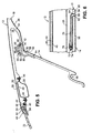
- each flap 14 is on the vehicle interior opposite side of each flap 14 in the vicinity each flap side edge 62 a spring element 72 is provided, so that each flap 14 two spring elements 72 are assigned.
- the Spring elements 72 each engage one of the side wall sections 70, whereby the spring elements 72 the side wall sections 70 and thus also the respective flap 14 in the Pretension when not in use. More specifically, it is in the exemplary embodiment shown with the spring elements 72 around simply angled wire sections, each a longer one first leg 74 and a shorter second leg 76 exhibit.
- the first leg 74 of the spring element 72 is in accordance with 3 and 6 substantially in the center of the respective side wall section 70 by means of at least one fabric loop 78 fixed, which wraps around the first leg 74 and on suitable Way, for example by gluing and / or sewing on the respective side wall section 70 is attached.
- the free end of the second Leg 76 of the spring element 72 is according to FIG. 4 and 5 rotatably mounted in a bearing block 80, which is in one piece with a bearing shell described in more detail below 82 is formed, which is adjacent to the flap 14 on the on the lower layer facing away from the vehicle interior 34 of the inner shell 10 is foamed.
- the spring elements 72 when pivoting the flap 14 from their non-use position in their Use position over the spanning side wall sections 70, which in this case on the first legs 74 of the spring elements 72 pull over the fabric loops 78, based on the respective Flap 14 are spring open to the outside.
- the flap 14 is off pivoted back into its non-use position, thus the spring elements spring back 72 the pivoting movement in which the first leg 74 over the fabric loops 78 on the side wall sections 70 and thus pull the flap 14 with the side wall portions 70 also from the parting lines 66 in relation to the respective flap 14 be pulled away inside.
- the side wall sections 70 and the spring elements 72 then lie immediately above the flap 14, as Fig. 6 shows.
- the hinge 58 and those aligned with each other Axes of rotation of the second legs 76 of the spring elements 72 in each assigned bracket 80 is not on a common Axis.
- an in 4 and 5 shown guide device for the pivoting movement the respective flap 14 is provided, which is complementary interlocking, causing the flap 14 to be guided
- Has circular arc sections which with respect to the pivot axis the flap 14 are arranged centered. More specifically is a bearing shell on both transverse sides of the respective flap 14 84 the hinge 58 adjacent to that of the vehicle interior opposite side of the flap 14 foamed on the flap 14, with an arcuate shape from each bearing shell 84 End 86 stretched out, each one of the mentioned Forms circular arc sections.
- the other sections of the arc are formed by arcuate slots 88, the in the respective flap 14 adjacent to the lower layer 34 of the inner shell 10 foamed bearing shells 82 are provided.
- 4 and 5 illustrate are the arcuate ends 86 of the flap side Bearing shells 84 are displaceable and essentially free of radial play in the arcuate slots 88 of the inner shell Bearing shells 82 added.
- the preferably made of a suitable plastic Bearing shells 82, 84 also form a holding device for releasable fixation of the respective flap 14 in its non-use position or their position of use, as described in the end shall be.
- This holding device points to both The transverse sides of the corresponding flap 14 each have two locking grooves 90, 92 on, of which a locking groove 90 of the non-use position the flap 14 (Fig. 4) is assigned while the other Locking groove 92 assigned to the position of use of the flap 14 (FIG. 5) is. 4 and 5 also show, the locking grooves 90, 92 suitably angularly spaced on a circular arc Slot 88 of the respective bearing shell 82 is formed, i.e.
- Locking grooves 90, 92 are in the illustrated embodiment with respect of the non-movable part of the inner shell 10 stationary.
- the holding device on both transverse sides of the corresponding flap 14 also one in the locking grooves 90, 92 on the arcuate slot 88 of the respective bearing shell 82 snap-in latch 94, the end of the circular arc End 86 of the corresponding bearing shell 84 formed, i.e. the is assigned to each flap 14.
- each flap 14 allows angular movement the flap 14 in the flap plane as well as translational Height movements of the flap 14 substantially prevented.
- translatory transverse movements of the flap 14 are essentially prevented by the hinge 58.
- the holding device described ensures defined end positions the respective flap 14 in its non-use position or their position of use, the holding device the flap 14 in their position of use also against the force of the spring elements 72 holds.
- the flap is formed as part of the inner shell and closes in their non-use position essentially flush with the surface the areas of the inner shell adjacent to the flap. in the The result is a very space-saving design of the flap arrangement achieved.
Landscapes
- Engineering & Computer Science (AREA)
- Mechanical Engineering (AREA)
- Vehicle Interior And Exterior Ornaments, Soundproofing, And Insulation (AREA)
- Body Structure For Vehicles (AREA)
- Laminated Bodies (AREA)
Applications Claiming Priority (2)
| Application Number | Priority Date | Filing Date | Title |
|---|---|---|---|
| DE10236595 | 2002-08-09 | ||
| DE10236595A DE10236595A1 (de) | 2002-08-09 | 2002-08-09 | Innenschale für Fahrzeugkarosserien |
Publications (2)
| Publication Number | Publication Date |
|---|---|
| EP1388446A2 true EP1388446A2 (fr) | 2004-02-11 |
| EP1388446A3 EP1388446A3 (fr) | 2004-04-07 |
Family
ID=30128800
Family Applications (1)
| Application Number | Title | Priority Date | Filing Date |
|---|---|---|---|
| EP03016743A Withdrawn EP1388446A3 (fr) | 2002-08-09 | 2003-07-23 | Garniture intérieure pour carosserie de véhicule |
Country Status (3)
| Country | Link |
|---|---|
| US (1) | US6908136B2 (fr) |
| EP (1) | EP1388446A3 (fr) |
| DE (1) | DE10236595A1 (fr) |
Cited By (1)
| Publication number | Priority date | Publication date | Assignee | Title |
|---|---|---|---|---|
| FR3017575A1 (fr) * | 2014-02-18 | 2015-08-21 | Peugeot Citroen Automobiles Sa | Agencement d'une galerie interieure dans l'habitacle d'un vehicule |
Families Citing this family (12)
| Publication number | Priority date | Publication date | Assignee | Title |
|---|---|---|---|---|
| US6991276B2 (en) * | 2003-05-20 | 2006-01-31 | Mccauley Alvin D | Luggage loft assembly |
| DE102004005484B4 (de) * | 2004-02-04 | 2011-05-26 | GM Global Technology Operations LLC, ( n. d. Ges. d. Staates Delaware ), Detroit | Kraftfahrzeug mit einer am Dach angeordneten Staueinrichtung |
| US20080073927A1 (en) * | 2006-09-22 | 2008-03-27 | Lear Corporation | Vehicle trim component storage compartment and method of making same |
| US20080100081A1 (en) * | 2006-10-26 | 2008-05-01 | Lear Corporation | Vehicle interior storage compartment |
| DE102007015709B4 (de) * | 2007-01-25 | 2009-09-03 | Webasto Ag | Fahrzeugdach |
| FR2929201A1 (fr) * | 2008-03-27 | 2009-10-02 | Renault Sas | Console d'un vehicule automobile |
| US8038199B2 (en) * | 2008-05-21 | 2011-10-18 | Marcus Automotive, Llc | Visor |
| US20110109117A1 (en) * | 2009-11-10 | 2011-05-12 | Marcus Automotive, LLC. | Pivoted visor assembly |
| US8925995B2 (en) | 2011-10-03 | 2015-01-06 | Marcus Automotive, Llc | Rotatable side window visor and glare shield |
| JP5820223B2 (ja) * | 2011-10-06 | 2015-11-24 | 豊和繊維工業株式会社 | 自動車用防音シート及びその製造方法並びに当該防音シートを用いた自動車用ダッシュサイレンサー |
| CN102582531A (zh) * | 2012-02-29 | 2012-07-18 | 重庆长安汽车股份有限公司 | 一种汽车顶盖装饰条 |
| DE102015208670B4 (de) * | 2014-05-16 | 2025-10-09 | Volkswagen Aktiengesellschaft | Dachrahmen |
Citations (3)
| Publication number | Priority date | Publication date | Assignee | Title |
|---|---|---|---|---|
| DE19947238A1 (de) | 1999-09-30 | 2001-04-12 | Meritor Automotive Gmbh | Fahrzeugdach |
| DE19959812A1 (de) | 1999-12-11 | 2001-06-21 | Meritor Automotive Gmbh | Sonnenblendenanordnung an einem Kraftfahrzeug-Dachmodul |
| DE10116593A1 (de) | 2001-04-03 | 2002-10-17 | Arvinmeritor Gmbh | Fahrzeugdach |
Family Cites Families (15)
| Publication number | Priority date | Publication date | Assignee | Title |
|---|---|---|---|---|
| DE2445408A1 (de) * | 1973-10-04 | 1975-04-17 | Einar Sigfrid Willgren | Blendschutzvorrichtung fuer fahrzeuge |
| US3953067A (en) * | 1974-09-18 | 1976-04-27 | Isola Richard A | Vehicle headliner construction |
| IT1208808B (it) * | 1985-05-31 | 1989-07-10 | Fiat Auto Spa | Padiglione per un veicolo e procedimento per la sua costruzione |
| US4674789A (en) * | 1986-02-13 | 1987-06-23 | Prince Corporation | Sun shield system |
| US5269060A (en) * | 1988-06-10 | 1993-12-14 | United Technologies Automotive, Inc. | Method of aligning and installing an automobile headliner by a previously attached sunshade assembly |
| US4958878A (en) * | 1989-08-21 | 1990-09-25 | Prince Corporation | Headliner with integral visor |
| US5823611A (en) * | 1995-09-18 | 1998-10-20 | Prince Corporation | Headliner with integral impact absorption panels |
| DE19709016C2 (de) * | 1997-03-06 | 1999-05-27 | Rockwell International Gmbh | Fahrzeugdach und Verfahren zur Montage des Fahrzeugdachs an einer Karosserie |
| DE19741265C1 (de) * | 1997-09-19 | 1998-10-08 | Bayerische Motoren Werke Ag | Im Innenraum eines Kraftfahrzeugs vorgesehenes Ablagefach, insbesondere an der Innenseite einer Fahrzeugtür |
| JP3099784B2 (ja) * | 1997-09-26 | 2000-10-16 | トヨタ自動車株式会社 | 頭部保護エアバッグ袋体を搭載した車両の内装品取付構造 |
| US6234570B1 (en) * | 1999-03-10 | 2001-05-22 | Lear Corporation | Integration of sunglass storage holder with pull handle assembly |
| DE19951659C2 (de) * | 1999-10-26 | 2002-07-25 | Arvinmeritor Gmbh | Fahrzeugdach, insbesondere Kraftfahrzeugdach |
| DE19959809B4 (de) * | 1999-12-11 | 2005-08-04 | Arvinmeritor Gmbh | Dachmodul für Kraftfahrzeuge |
| US6296293B1 (en) * | 2000-04-28 | 2001-10-02 | Lear Corporation | Slidable auxiliary sun visor assembly |
| GB0205482D0 (en) | 2002-03-08 | 2002-04-24 | Bae Systems Plc | Improvements in or relating to infra red camera calibration |
-
2002
- 2002-08-09 DE DE10236595A patent/DE10236595A1/de not_active Ceased
-
2003
- 2003-07-23 EP EP03016743A patent/EP1388446A3/fr not_active Withdrawn
- 2003-08-08 US US10/638,127 patent/US6908136B2/en not_active Expired - Fee Related
Patent Citations (3)
| Publication number | Priority date | Publication date | Assignee | Title |
|---|---|---|---|---|
| DE19947238A1 (de) | 1999-09-30 | 2001-04-12 | Meritor Automotive Gmbh | Fahrzeugdach |
| DE19959812A1 (de) | 1999-12-11 | 2001-06-21 | Meritor Automotive Gmbh | Sonnenblendenanordnung an einem Kraftfahrzeug-Dachmodul |
| DE10116593A1 (de) | 2001-04-03 | 2002-10-17 | Arvinmeritor Gmbh | Fahrzeugdach |
Cited By (1)
| Publication number | Priority date | Publication date | Assignee | Title |
|---|---|---|---|---|
| FR3017575A1 (fr) * | 2014-02-18 | 2015-08-21 | Peugeot Citroen Automobiles Sa | Agencement d'une galerie interieure dans l'habitacle d'un vehicule |
Also Published As
| Publication number | Publication date |
|---|---|
| US20040066054A1 (en) | 2004-04-08 |
| DE10236595A1 (de) | 2004-02-26 |
| US6908136B2 (en) | 2005-06-21 |
| EP1388446A3 (fr) | 2004-04-07 |
Similar Documents
| Publication | Publication Date | Title |
|---|---|---|
| DE19959809B4 (de) | Dachmodul für Kraftfahrzeuge | |
| EP0964814B1 (fr) | Toit de vehicule et procede de montage de ce toit sur une carrosserie | |
| EP1024972B1 (fr) | Porte de vehicule a moteur | |
| DE69705875T3 (de) | Mit Aussenwand versehenes,geformtes Rahmenmodul | |
| DE69203615T2 (de) | Verfahren zur Herstellung einer Fahrzeugtür, insbesondere für ein Automobil; Unter-Einheit zur Anwendung des Verfahrens und Tür welche durch die Anwendung des Verfahrens erhalten wird. | |
| DE19801842A1 (de) | Fahrzeugtür | |
| EP1088749A2 (fr) | Toit de véhicule | |
| DE10233280B4 (de) | Fahrzeugdachmodul | |
| DE10101450A1 (de) | Fahrzeugdach, insbesondere Kraftfahrzeugdach | |
| EP1388446A2 (fr) | Garniture intérieure pour carosserie de véhicule | |
| EP1651458B1 (fr) | Portiere de vehicule automobile | |
| WO2002060720A2 (fr) | Sous-ensemble de portiere destine a une portiere automobile | |
| DE10144166A1 (de) | Schloss für eine Kraftfahrzeugtür | |
| DE10334143B4 (de) | Kraftfahrzeugtür | |
| EP1106489B1 (fr) | Paresoleil pour module de toiture de véhicules | |
| DE10116593B4 (de) | Fahrzeugdach | |
| DE102006015091B4 (de) | Kraftfahrzeug-Innenausstattungsfeld, das eine vereinigte Dichtung aufweist, Verfahren zu dessen Herstellung und damit ausgestattetes KFZ | |
| DE60022924T2 (de) | Innenteil einer Fahrzeugtür, korrespondierende Tür und Verfahren für den Zusammenbau einer solchen Tür | |
| DE102018122796A1 (de) | Fahrzeugtür | |
| DE10047818A1 (de) | Befestigungsanordnung für eine Kraftfahrzeug-Innenverkleidung | |
| DE102006009701A1 (de) | Mehrteilige Türverkleidung | |
| DE10234526B4 (de) | Kraftfahrzeugtür | |
| EP2200849A1 (fr) | Support d'organes pour un véhicule à moteur, notamment pour une portière de véhicule, et portière de véhicule | |
| DE20220552U1 (de) | Kraftfahrzeugtür | |
| WO2004110799A1 (fr) | Portiere de vehicule automobile |
Legal Events
| Date | Code | Title | Description |
|---|---|---|---|
| PUAI | Public reference made under article 153(3) epc to a published international application that has entered the european phase |
Free format text: ORIGINAL CODE: 0009012 |
|
| AK | Designated contracting states |
Kind code of ref document: A2 Designated state(s): AT BE BG CH CY CZ DE DK EE ES FI FR GB GR HU IE IT LI LU MC NL PT RO SE SI SK TR |
|
| AX | Request for extension of the european patent |
Extension state: AL LT LV MK |
|
| PUAL | Search report despatched |
Free format text: ORIGINAL CODE: 0009013 |
|
| AK | Designated contracting states |
Kind code of ref document: A3 Designated state(s): AT BE BG CH CY CZ DE DK EE ES FI FR GB GR HU IE IT LI LU MC NL PT RO SE SI SK TR |
|
| AX | Request for extension of the european patent |
Extension state: AL LT LV MK |
|
| RIC1 | Information provided on ipc code assigned before grant |
Ipc: 7B 60J 3/02 A |
|
| 17P | Request for examination filed |
Effective date: 20040423 |
|
| AKX | Designation fees paid |
Designated state(s): DE FR IT NL |
|
| STAA | Information on the status of an ep patent application or granted ep patent |
Free format text: STATUS: THE APPLICATION HAS BEEN WITHDRAWN |
|
| 18W | Application withdrawn |
Effective date: 20070426 |