EP1388458A2 - Fahrzeugsitz mit Schwenkmechanismus - Google Patents
Fahrzeugsitz mit Schwenkmechanismus Download PDFInfo
- Publication number
- EP1388458A2 EP1388458A2 EP03017000A EP03017000A EP1388458A2 EP 1388458 A2 EP1388458 A2 EP 1388458A2 EP 03017000 A EP03017000 A EP 03017000A EP 03017000 A EP03017000 A EP 03017000A EP 1388458 A2 EP1388458 A2 EP 1388458A2
- Authority
- EP
- European Patent Office
- Prior art keywords
- actuating
- seat
- engaging projection
- vehicle seat
- actuating member
- Prior art date
- Legal status (The legal status is an assumption and is not a legal conclusion. Google has not performed a legal analysis and makes no representation as to the accuracy of the status listed.)
- Granted
Links
Images





Classifications
-
- B—PERFORMING OPERATIONS; TRANSPORTING
- B60—VEHICLES IN GENERAL
- B60N—SEATS SPECIALLY ADAPTED FOR VEHICLES; VEHICLE PASSENGER ACCOMMODATION NOT OTHERWISE PROVIDED FOR
- B60N2/00—Seats specially adapted for vehicles; Arrangement or mounting of seats in vehicles
- B60N2/02—Seats specially adapted for vehicles; Arrangement or mounting of seats in vehicles the seat or part thereof being movable, e.g. adjustable
- B60N2/04—Seats specially adapted for vehicles; Arrangement or mounting of seats in vehicles the seat or part thereof being movable, e.g. adjustable the whole seat being movable
- B60N2/06—Seats specially adapted for vehicles; Arrangement or mounting of seats in vehicles the seat or part thereof being movable, e.g. adjustable the whole seat being movable slidable
-
- B—PERFORMING OPERATIONS; TRANSPORTING
- B60—VEHICLES IN GENERAL
- B60N—SEATS SPECIALLY ADAPTED FOR VEHICLES; VEHICLE PASSENGER ACCOMMODATION NOT OTHERWISE PROVIDED FOR
- B60N2/00—Seats specially adapted for vehicles; Arrangement or mounting of seats in vehicles
- B60N2/02—Seats specially adapted for vehicles; Arrangement or mounting of seats in vehicles the seat or part thereof being movable, e.g. adjustable
- B60N2/20—Seats specially adapted for vehicles; Arrangement or mounting of seats in vehicles the seat or part thereof being movable, e.g. adjustable the back-rest being tiltable, e.g. to permit easy access
-
- B—PERFORMING OPERATIONS; TRANSPORTING
- B60—VEHICLES IN GENERAL
- B60N—SEATS SPECIALLY ADAPTED FOR VEHICLES; VEHICLE PASSENGER ACCOMMODATION NOT OTHERWISE PROVIDED FOR
- B60N2/00—Seats specially adapted for vehicles; Arrangement or mounting of seats in vehicles
- B60N2/02—Seats specially adapted for vehicles; Arrangement or mounting of seats in vehicles the seat or part thereof being movable, e.g. adjustable
- B60N2/20—Seats specially adapted for vehicles; Arrangement or mounting of seats in vehicles the seat or part thereof being movable, e.g. adjustable the back-rest being tiltable, e.g. to permit easy access
- B60N2/206—Seats specially adapted for vehicles; Arrangement or mounting of seats in vehicles the seat or part thereof being movable, e.g. adjustable the back-rest being tiltable, e.g. to permit easy access to a position in which it can be used as a support for objects, e.g. as a tray
-
- B—PERFORMING OPERATIONS; TRANSPORTING
- B60—VEHICLES IN GENERAL
- B60N—SEATS SPECIALLY ADAPTED FOR VEHICLES; VEHICLE PASSENGER ACCOMMODATION NOT OTHERWISE PROVIDED FOR
- B60N2/00—Seats specially adapted for vehicles; Arrangement or mounting of seats in vehicles
- B60N2/02—Seats specially adapted for vehicles; Arrangement or mounting of seats in vehicles the seat or part thereof being movable, e.g. adjustable
- B60N2/22—Seats specially adapted for vehicles; Arrangement or mounting of seats in vehicles the seat or part thereof being movable, e.g. adjustable the back-rest being adjustable
- B60N2/235—Seats specially adapted for vehicles; Arrangement or mounting of seats in vehicles the seat or part thereof being movable, e.g. adjustable the back-rest being adjustable by gear-pawl type mechanisms
- B60N2/2352—Seats specially adapted for vehicles; Arrangement or mounting of seats in vehicles the seat or part thereof being movable, e.g. adjustable the back-rest being adjustable by gear-pawl type mechanisms with external pawls
-
- B—PERFORMING OPERATIONS; TRANSPORTING
- B60—VEHICLES IN GENERAL
- B60N—SEATS SPECIALLY ADAPTED FOR VEHICLES; VEHICLE PASSENGER ACCOMMODATION NOT OTHERWISE PROVIDED FOR
- B60N2/00—Seats specially adapted for vehicles; Arrangement or mounting of seats in vehicles
- B60N2/24—Seats specially adapted for vehicles; Arrangement or mounting of seats in vehicles for particular purposes or particular vehicles
- B60N2/30—Non-dismountable or dismountable seats storable in a non-use position, e.g. foldable spare seats
- B60N2/3002—Non-dismountable or dismountable seats storable in a non-use position, e.g. foldable spare seats back-rest movements
- B60N2/3004—Non-dismountable or dismountable seats storable in a non-use position, e.g. foldable spare seats back-rest movements by rotation only
- B60N2/3009—Non-dismountable or dismountable seats storable in a non-use position, e.g. foldable spare seats back-rest movements by rotation only about transversal axis
- B60N2/3011—Non-dismountable or dismountable seats storable in a non-use position, e.g. foldable spare seats back-rest movements by rotation only about transversal axis the back-rest being hinged on the cushion, e.g. "portefeuille movement"
Definitions
- the present invention relates to a vehicle seat having a folding mechanism, in particular, it relates to a vehicle seat having a folding mechanism which enables a second seat of a minivan to be slidable forward and backward relative to a vehicle and enables the second seat to be used as a table.
- a second seat of a minivan according to the related art is constructed such that by folding the seat back forward to a predetermined inclination angle, the second seat advances forward on the floor of the vehicle to facilitate getting in and out of the rear seat via the rear door.
- second seats that are usable as a table by further folding the seat back from the predetermined forward inclination angle into the seat cushion.
- a second seat in this instance comprises a seat reclining apparatus and a seat-slide apparatus, which in combination give a so-called "walk-in” capability.
- This sort of capability facilitates entry-exit to or from the third seat by propelling the second seat forward when the seat back thereof is folded forward to create more clearance for a passenger.
- the second seat is mounted on the seat-slide apparatus to be slidable thereon backward and forward relative to the vehicle.
- the second seat is under constant urging of a spring to move forward, but is fixable at any desired position along the seat-slide apparatus in a state herein called "seat lock" by means of a locking mechanism of the seat-slide apparatus.
- a seat reclining apparatus Sa in Fig. 14 by folding the seat back forward, an arm plate 2 rotates in the direction of the arrow and a pin 5, which is formed integrally on arm plate 2, contacts with an end of a walk-in lever 6 to rotate walk-in lever 6 counter-clockwise according to Fig. 14, causing a wire end 7 of a wire 8 to be pulled upward toward seat reclining apparatus Sa.
- Wire 8 is connected to the locking mechanism of the seat-slide apparatus, and while the locking mechanism is urged to be locked to prevent seat sliding, pulling of wire 8 causes the locking mechanism to unlock, letting the seat be slidable.
- An aspect of the present invention resides in a vehicle seat having a folding mechanism, the vehicle seat being both fixable and slidable forward and backward relative to the vehicle, the vehicle seat comprising locking means for allowing or preventing seat sliding when unlocked or locked respectively, a wire joined to the locking means at one end thereof, the wire unlocking or locking the locking means when pulled or at rest respectively, a base member disposed above the locking means, a first actuating member, supported to be rotatable in a first direction and a second direction on the base member, a second actuating member, rotatably supported on the base member coaxially with the first actuating member and joined to another end of the wire, the second actuating member allowing the wire to be at rest when in a first position and pulling the wire when rotated by the first actuating member to be in a second position when the first actuating member is rotated in the second direction, first urging means for urging the first actuating member in the second direction, disposed between the first actuating member and the second
- a vehicle seat having a folding mechanism, the vehicle seat being both fixable and slidable forward and backward relative to the vehicle, the vehicle seat comprising, locking means for allowing or preventing seat sliding when unlocked or locked respectively, a wire joined to the locking means at one end thereof, the wire unlocking or locking the locking means when pulled or at rest respectively, a base member disposed above the locking means, bottom actuating means for pulling the wire, rotatably supported on the base member and joined to another end of the wire, the bottom actuating means allowing the wire to be at rest when in a first position and pulling the wire when in a second position, top actuating means for rotating the bottom actuating means from the first position to the second position, rotatably supported on the base member coaxially with the bottom actuating means, an upper member rotatably supported on the base member, and an engaging projection member rotating integrally with the upper member, the engaging projection member being in one of a first area, a second area, a third area, and
- a further aspect of the present invention resides in a vehicle seat comprising a seat cushion, a seat back swingably connected above the seat cushion, a seat slide mechanism disposed between the seat cushion and a floor of a vehicle, the seat slide mechanism being capable of allowing the seat cushion to slide in the fore-and-aft direction of the vehicle, and a lock mechanism putting the seat slide mechanism in a release state of allowing sliding movement of the seat cushion when the seat back is folded forward at a first angle within a first angle range, the lock mechanism putting the seat slide mechanism in a lock state of prohibiting the sliding movement of the seat cushion when the seat back is folded forward at a second angle within a second angle range greater than the first angle range relative to the seat back before folding forward.
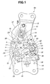
- Fig. 1 is a front view showing a seat reclining apparatus according to a first embodiment of the present invention.
- Fig. 2 is a back view showing the seat reclining apparatus.
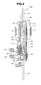
- Fig. 3 is a right view showing the seat reclining apparatus.
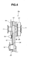
- Fig. 4 is a cross-sectional view of the seat reclining apparatus along the line IV-IV of Fig. 1.
- Fig. 5 is a back view showing an operation of the seat reclining apparatus in Fig. 2.
- Fig. 6 is a schematic view of a side of a vehicle seat showing an initial position of the seat reclining apparatus and an enlarged portion view thereof.
- Fig. 7 is a schematic view of a left side of the vehicle seat showing a walk-in operation of the seat reclining apparatus and an enlarged portion view thereof.
- Fig. 8 is a schematic view of the left side of the vehicle seat showing a temporary stop position of the walk-in operation of the seat reclining apparatus and an enlarged portion view thereof.
- Fig. 9 is a schematic view of the left side of the vehicle seat functioning as a table, showing the seat reclining apparatus and an enlarged portion view thereof.
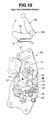
- Fig. 10 is a schematic view of the left side of the vehicle seat showing the seat reclining apparatus during operation of raising the seat back after use as a table and an enlarged portion view thereof.
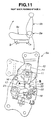
- Fig. 11 is a schematic view of the left side of the vehicle seat showing the seat reclining apparatus during operation of raising the seat back after use as a table and an enlarged portion view thereof.
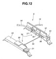
- Fig. 12 is a perspective view showing a seat-slide apparatus of the present invention.
- Fig. 13 is a front view showing a second embodiment according to the present invention.
- Fig. 14 is a front view showing a seat reclining apparatus according to the prior art.
- FIGs. 1 through 12 there is discussed a first embodiment of a vehicle seat having a folding mechanism in accordance with the present invention.
- a vehicle seat according to the present invention is a second seat, the seat comprising a folding "walk-in" mechanism.
- a folding mechanism according to the present invention comprises a seat reclining apparatus Sa and a seat-slide apparatus S.
- Seat reclining apparatus Sa according to the present invention is first herein explained with reference to Figs. 1 through 5.
- seat reclining apparatus Sa comprises a base plate 10 which is fixed to a seat cushion Sc of the seat, and a holder plate 15.
- Base plate 10 comprises a center shaft 11 which supports an arm plate 12 to be freely rotatable thereon, arm plate 12 being fixed to a seat back Sb of the seat.
- Arm plate 12 comprises a joining pin 13 which is formed at a right angle thereto.
- a walk-in plate 14 is axially supported to be rotatable on center shaft 11 which projects through holder plate 15. One end of walk-in plate 14 engages with joining pin 13 so that walk-in plate 14 rotates integrally with arm plate 12.
- Base plate 10 further comprises a shaft 18 which axially supports a first lever 17 to be freely rotatable.
- Walk-in plate 14 comprises a pin 16
- first lever 17 comprises a surface A and a surface B which lie within an arc formed by a rotation of pin 16, formed respectively on the front and back of first lever 17 relative to the vehicle.
- a second lever 21 is also axially supported on shaft 18 to be freely rotatable between base plate 10 and first lever 17 so that second lever 21 and first lever 17 are respectively on the bottom and top with respect to base plate 10.
- Second lever 21 is connected to a wire 19 through a wire end 20, wire 19 joining to seat-slide apparatus S.
- Second lever 21 comprises a stopper pin 22, and first lever 17 comprises a nub portion 23 which projects therefrom to contact with stopper pin 22.
- two springs are wound about shaft 18 between first lever 17 and second lever 21.
- a first spring 24 is resiliently attached between first lever 17 and second lever 21, and urges first lever 17 to rotate clockwise according to Fig. 1 backward toward the back of seat back Sb so that nub portion 23 contacts with stopper pin 22, and a second spring 25 is resiliently attached between second lever 21 and base plate 10, and urges second lever 21 to rotate counter-clockwise according to Fig. 1 forward toward the front of seat back Sb.
- a lower portion of arm plate 12 is formed as an arc portion of a predetermined radius about center shaft 11.
- a first tooth portion 26 and a second tooth portion 27 are formed on a periphery of the arc portion for adjusting reclining, separated by an intervening toothless portion.
- a reclining lock mechanism which engages and disengages with first tooth portion 26 and second tooth portion 27 is disposed between base plate 10 and first holder plate 15. Second tooth portion 27 is used to fix arm plate 12 to base plate 10 when the second seat is being used as a table.
- the reclining lock mechanism comprises a shaft 30 which is supported by first holder plate 15 and base plate 10, and a tooth member 29 which is axially supported on shaft 30 to be swingable. Tooth member 29 comprises a tooth portion 28 at an upper portion of an end thereof away from shaft 30, tooth portion 28 engaging and disengaging with first tooth portion 26 and second tooth portion 27.
- the reclining lock mechanism further comprises a shaft 32 which is supported on first holder plate 15 and base plate 10 and a cam 31 which is axially supported to be rotatable thereon. Cam 31 serves to swing tooth member 29.
- a lever 33 is joined to shaft 32 to rotate integrally therewith, and a return spring 34 is resiliently attached to lever 33 between lever 33. and base plate 10.
- a reclining lever or knob would be attached to shaft 32 with which to rotate cam 31.
- joining pin 13 is formed to project from the back surface of arm plate 12, joining arm plate 12 to a stopper disk 35 which is axially supported on center shaft 11, so that stopper disk 35 rotates integrally with arm plate 12.
- Stopper disk 35 comprises a stopper surface 36 which is crank-shaped to be contacted with an upper end of a stopper lever 37 which is L-shaped, stopper lever 37 being axially supported at another end thereof.
- a spring 40 is resiliently attached between stopper lever 37 and a second holder plate 39 to constantly urge stopper lever 37 in a direction that an edge of the upper end of stopper lever 37 is in sliding contact with stopper disk 35 to be contactable with stopper portion 36 of the arc portion.
- a shaft 38 is supported to be freely rotatable on base plate 10, and although not shown in Fig. 3, a table lever or knob for folding the seat into a table is attached thereto. Also, a spiral spring is attached, with an outer end portion thereof latched to joining pin 13 and an inner end portion thereof latched to center shaft 11, so that arm plate 12 is constantly urged to rotate in a direction to incline forward.
- a reclining lever or knob rotates cam 31, causing a lobe portion c of cam 31 shown in Fig. 1 to move reciprocatingly between a sliding contact portion a and a depression portion b of tooth member 29.
- This action causes tooth member 29 to move reciprocatingly in an up or down direction about shaft 30, and it is possible to engage and disengage tooth portion 28 with first tooth portion 26 or second tooth portion 27. That is, movement of lobe portion c of cam 31 into depression portion b of tooth member 29 causes tooth member 29 to swing counter-clockwise according to Fig.
- tooth portion 28 disengages from first tooth portion 26, and opposite to this, movement of lobe portion c of cam 31 to sliding contact portion a of tooth member 29 causes tooth member 29 to swing clockwise according to Fig. 1 about shaft 30, whereby tooth portion 28 engages with either first tooth portion 26 or second tooth portion 27.
- seat-slide apparatus S comprises lower rails 50 and 51 which are fixed to the vehicle floor, and upper rails 52 and 53 which are engaged with lower rails 50 and 51 to be movable forward and backward relative to the vehicle.
- upper rails 52 and 53 are constantly under urging of a spring (not shown) to move forward.
- Lock mechanism portions 54 and 54 are fixed to upper rails 52 and 53, and comprise lock catches 55 and 55.
- Lower rails 50 and 51 comprise lock holes (not shown) to be engaged by lock catches 55 and 55.
- Seat-slide apparatus S is fixable by lock catches 55 and 55 engaging the lock holes of lower rails 50 and 51 at a position where upper rails 52 and 53 have been moved to, entering a state of seat lock.
- Seat-slide apparatus S also comprises a lever 56 for rotating lock catches 55 and 55.
- Lever 56 integrally comprises a branch lever portion 57 to which another end of wire 19 is joined.
- Lever 56 is axially supported by one of lock mechanism portions 54 and 54 to be rotatable.
- a joining rod 59 is provided so that both of lock mechanism portions 54 and 54 are moved synchronously by action of lever 56 on only one of lock mechanism portions 54 and 54.
- Lock catches 55 and 55 are constantly urged to rotate to engage with lock holes in lower rails 50 and 51 by a return spring 58.
- lever 56 of seat-slide apparatus S is axially rotated against the force of return spring 58 by wire 19 pulling on branch lever portion 57, and lock catches 55 and 55 come out of lock holes in lower rails 50 and 51, releasing the state of seat lock.
- second lever 21 Since nub portion 23 of first lever 17 is in contact with stopper pin 22 of second lever 21, second lever 21 must also rotate integrally with first lever 17 when pin 16 pushes and rotates first lever 17 by a predetermined angle clockwise according to Fig. 8, and both are rotated clockwise backward according to Fig. 8 against the force of second spring 25. Then, as first lever 17 and second lever 21 rotate to a predetermined forward inclination of approximately 45° under rotational contact of pin 16 against surface A, wire 19 is pulled as shown in Fig. 8, and the state of seat lock of seat-slide apparatus S is released. Thus, the seat is pushed forward in the vehicle by force of the spring which constantly urges upper rails 52 and 53 of seat-slide apparatus S frontward in the vehicle.
- stopper disk 35 when seat back Sb folds forward to a predetermined forward inclination angle, stopper disk 35 has also rotated integrally with arm plate 12 clockwise according to Fig. 5 about center shaft 11, until an end of stopper lever 37 has contacted with stopper portion 36. Further rotation of stopper disk 35 and arm plate 12 integral therewith is thereby prevented, and folding forward of seat back Sb and therefore armplate 12 is maintained at this position. In this way stopper disk 35 and stopper lever 37 are used as an enter-exit stop position mechanism to limit forward inclination of arm plate 12 toward base plate 10 beyond this predetermined angle or position.
- the seat according to the first embodiment can be used stably as a table in a state of seat lock after it has been moved forward in the vehicle.
- the upper end thereof is caused to come away from stopper portion 36, allowing arm plate 12 and thus seat back Sb to be rotatable to a greater angle range, i.e., a range comprised of angles which are greater relative to seat back Sb before being folded forward than angles comprising the previously discussed angle range, this greater angle range including an angle at which seat back Sb is in a substantially horizontal state.
- Pin 16 of walk-in plate 14 comes away from surface A of first lever 17 and out of contact with first lever 17 as shown in Fig. 9, and second lever 21 rotates counter-clockwise about shaft 18 by the force of second spring 25 and returns to an original position of being rotated forward relative to the vehicle, and at the same time, first lever 17 returns to an original position by stopper pin 22 of second lever 21 pushing nub portion 23 of first lever 17. Therefore wire 19 returns to an original state by the spring force of lock mechanism portions 54 and 54 of seat-slide apparatus S and a state of seat lock is entered, i.e., the seat is immovably fixed in place.
- tooth portion 28 of tooth member 29 had already been situated at the toothless portion existing between first tooth portion 26 and second tooth portion 27, tooth portion 28 of tooth member 29 engages with second tooth portion 27 of arm plate 12 once arm plate 12 rotates to a substantially horizontal state, and thus, as shown in Fig. 9, seat back Sb is locked in a state of lying on top of seat cushion Sc in a substantially horizontal state.
- first tooth portion 26 moves to a position to be engageable with tooth portion 28 of tooth member 29, and although the upper end of stopper lever 37 is in contact with the arc portion of stopper disk 35, it is possible to raise seat back Sb without the upper end of stopper lever 37 engaging stopper surface 36.
- pin 16 of walk-in plate 14 contacts with surface B of first lever 17, then, as shown in Fig. 11, accompanying rotation of arm plate 12, pin 16 moves in an arc and first lever 17 is rotated counter-clockwise according to Fig. 11 about shaft 18 against the force of first spring 24 separately and individually from second lever 21 which remains stationary, and nub portion 23 comes away from stopper pin 22. Pin 16 continues to move toward the boundary between surfaces A and B, and this motion continues until pin 16 completely clears surface B. Once pin 16 has passed surface B, contact is discontinued between pin 16 and first lever 17. Accordingly, first lever 17 returns to an original state by the force of first spring 24 where nub portion 23 is once again in contact with stopper pin 22, as shown in Fig. 6.
- a reclining apparatus in the second embodiment is called a round-type seat recliner, as can be known from Japanese patent No. 2,645,583.
- disks or plates are fixed to a seat cushion and a seat back respectively, designed so that their faces are in mutual contact and that one of which is rotatable.
- a lock tooth portion is formed on an inner circumferential surface of the rotatable disk, and a lock gear having a tooth portion is located inside of the fixed disk.
- the lock gear engages and disengages with the lock tooth portion through action of a cam with which the lock gear is in sliding contact, the cam being urged by a spring.
- the cam has an operating axle in a center thereof and by rotating the operating axle, it is possible to adjust the inclination angle of the seat back.
- a seat reclining apparatus of a round-type seat recliner is joined to a seat-slide apparatus which is fixed to a vehicle floor and movable backward and forward relative to the vehicle as well as being fixable.
- the seat reclining apparatus comprises a base plate 10a which is fixed to a seat cushion and an arm plate 12a which is fixed to a seat back.
- a mount member 60 is supported on base plate 10a, and a cover member 61 is supported on arm plate 12a, mount member 60 and cover member 61 engaging to be rotatable relative to one another.
- At least one lock gear is internally mounted, which is movable reciprocally in the radial direction to engage and disengage with at least one of a plurality of lock tooth portions formed on an inner circumferential surface of cover member 61, via a pair of left and right sliding guide portions disposed on an inner surface of mount member 60.
- an operating shaft 62 disposed at the center of both mount member 60 and cover member 61 one or more lock gears engage or disengage with at least one lock tooth portion of cover member 61, and in this way it is possible to freely adjust the inclination angle of the seat back.
- stopper lever 37 of Fig. 2 which is for maintaining a predetermined forward inclination angle of seat back Sb, is disposed on another reclining apparatus in this embodiment, of which there are individual left and right symmetrical structures. That is, supposing the reclining apparatus structure of Fig. 13 to be the outer reclining apparatus of the pair, stopper lever 37 is disposed on the inner reclining apparatus. Further, an outer circumferential surface of arm plate 12a of the inner reclining apparatus is formed into an arc portion, and comprises a stopper surface thereon in the same manner as stopper surface 36 on the arc portion of stopper disk 35. Therefore, the features of the second embodiment are the same as those of the first embodiment, supposing the reclining apparatus structure of Fig. 1 to be the outer side and the reclining apparatus structure of Fig. 2 to be the reclining apparatus of the inner side.
- a state of seat lock between seat reclining apparatus Sa and seat-slide apparatus S is released by folding seat back Sb so that seat back Sb is inclined within a predetermined range of forward inclination angles either for entering and exiting the third seat or for use as a table, whereby the seat becomes movable forward in the vehicle.
- the state of seat lock between seat-slide apparatus S and seat reclining apparatus Sa is once again entered, to achieve a sure stability with the second seat.
- first lever 17 and second lever 21 are designed to function as separate elements, it is possible to raise seat back Sb of the seat from a state as a table with only first lever 17 needing to pivot.
- stopper lever 37 used for maintaining seat back Sb at a predetermined inclination, from an outer side of the seat to an inner side if it is felt to be more convenient.
- seat back Sb stops at a predetermined inclination angle for entering or exiting the third seat as a vehicle enter-exit stop position without rotating to a forwardmost position, it is possible to put one's hand on inclined seat back Sb as a support to enter or exit the third seat. Also, since seat back Sb is not locked, returning seat back Sb is simplified. Therefore, entering and exiting is improved.
- walk-in mechanism and the enter-exit stop position mechanism can be set on either outer or inner seat reclining apparatus of a vehicle seat, they can be easily set without affecting vehicle seat structure or other layout conditions.
- the present invention is usable when a passenger enters or exits the third seat of the vehicle, or when wishing to use the second seat as a table.
Landscapes
- Engineering & Computer Science (AREA)
- Aviation & Aerospace Engineering (AREA)
- Transportation (AREA)
- Mechanical Engineering (AREA)
- Seats For Vehicles (AREA)
- Chairs For Special Purposes, Such As Reclining Chairs (AREA)
Applications Claiming Priority (2)
| Application Number | Priority Date | Filing Date | Title |
|---|---|---|---|
| JP2002222765 | 2002-07-31 | ||
| JP2002222765A JP2004058928A (ja) | 2002-07-31 | 2002-07-31 | 車両用シートの折り畳み機構 |
Publications (3)
| Publication Number | Publication Date |
|---|---|
| EP1388458A2 true EP1388458A2 (de) | 2004-02-11 |
| EP1388458A3 EP1388458A3 (de) | 2008-01-16 |
| EP1388458B1 EP1388458B1 (de) | 2012-12-19 |
Family
ID=30437690
Family Applications (1)
| Application Number | Title | Priority Date | Filing Date |
|---|---|---|---|
| EP03017000A Expired - Lifetime EP1388458B1 (de) | 2002-07-31 | 2003-07-25 | Fahrzeugsitz mit Schwenkmechanismus |
Country Status (3)
| Country | Link |
|---|---|
| US (1) | US6986551B2 (de) |
| EP (1) | EP1388458B1 (de) |
| JP (1) | JP2004058928A (de) |
Cited By (2)
| Publication number | Priority date | Publication date | Assignee | Title |
|---|---|---|---|---|
| EP2055524A1 (de) * | 2007-10-30 | 2009-05-06 | Aisin Seiki Kabushiki Kaisha | Sitzvorrichtung für ein Fahrzeug |
| DE102013000164A1 (de) | 2013-01-09 | 2014-07-10 | Faurecia Autositze Gmbh | Fahrzeugsitz, insbesondere für einen Pkw |
Families Citing this family (40)
| Publication number | Priority date | Publication date | Assignee | Title |
|---|---|---|---|---|
| US7270375B2 (en) | 2005-05-09 | 2007-09-18 | Bae Industries, Inc. | Push/pull disengage mechanism for use with a rear row seat for selective seat tumble or removal from a vehicle |
| JP4761935B2 (ja) * | 2005-11-01 | 2011-08-31 | 富士機工株式会社 | シートリクライニング装置 |
| US20080122280A1 (en) * | 2006-09-08 | 2008-05-29 | Ford Global Technologies, Llc | Multifunction vehicular seat |
| JP2008295695A (ja) * | 2007-05-31 | 2008-12-11 | Fuji Kiko Co Ltd | シートリクライニング装置 |
| JP4302756B2 (ja) | 2007-06-29 | 2009-07-29 | トヨタ紡織株式会社 | 車両用シート |
| JP4354502B2 (ja) | 2007-06-29 | 2009-10-28 | トヨタ紡織株式会社 | 車両用シート |
| FR2921024B1 (fr) * | 2007-09-17 | 2009-11-06 | Renault Sas | Dispositif de maintien de deverrouillage de l'articulation pour siege inclinable de vehicule |
| US7819479B2 (en) * | 2007-10-10 | 2010-10-26 | Lear Corporation | Vehicle seat assembly having walk-in and fold-flat features |
| DE102008006980A1 (de) * | 2008-01-31 | 2009-08-06 | Lear Corporation, Southfield | Fahrzeugsitzeinrichtung |
| JP5518293B2 (ja) * | 2008-02-19 | 2014-06-11 | テイ・エス テック株式会社 | 車両用シートのシートスライド装置及び車両用格納シート |
| JP5181866B2 (ja) | 2008-06-24 | 2013-04-10 | トヨタ紡織株式会社 | 車両用シートの切換機構 |
| JP5270979B2 (ja) * | 2008-06-26 | 2013-08-21 | シロキ工業株式会社 | シート |
| JP5221226B2 (ja) * | 2008-07-01 | 2013-06-26 | シロキ工業株式会社 | シート |
| JP5309746B2 (ja) | 2008-07-15 | 2013-10-09 | トヨタ紡織株式会社 | 車両用シート |
| EP2321146B9 (de) * | 2008-08-07 | 2018-05-02 | Magna Seating Inc. | Versenkbarer sitz mit kipp-gleit-mechanismus |
| KR101054778B1 (ko) | 2008-12-01 | 2011-08-05 | 주식회사다스 | 시트의 워크인 및 폴딩장치 |
| EP2428393B1 (de) * | 2010-09-10 | 2019-11-13 | Faurecia Automotive Seating, Inc. | Easy-Entry-Rückenlehnenlösesystem für Fahrzeugsitz |
| KR101578944B1 (ko) | 2010-12-24 | 2015-12-18 | 주식회사다스 | 차량 시트의 폴딩 겸용 워크인 장치 |
| JP5880312B2 (ja) * | 2012-06-26 | 2016-03-09 | トヨタ紡織株式会社 | 車両用シート |
| US9545857B2 (en) * | 2012-07-16 | 2017-01-17 | Faurecia Automotive Seating, Llc | Recliner hold-open mechanism for a vehicle seat |
| JP5895810B2 (ja) * | 2012-10-23 | 2016-03-30 | トヨタ紡織株式会社 | 車両用シート |
| DE102014207606B4 (de) * | 2013-12-02 | 2024-09-05 | Keiper Seating Mechanisms Co., Ltd. | Vorschwenkmechanismus für einen Fahrzeugsitz und Fahrzeugsitz |
| KR101500211B1 (ko) * | 2013-12-03 | 2015-03-06 | 현대자동차주식회사 | 워크인 메모리 기능을 가지는 차량용 시트레일 장치 |
| JP6295763B2 (ja) * | 2014-03-25 | 2018-03-20 | アイシン精機株式会社 | シート装置 |
| US9403447B2 (en) * | 2014-05-15 | 2016-08-02 | Fca Us Llc | Vehicle seat including an interlock assembly |
| CN104627035B (zh) * | 2015-01-28 | 2017-10-27 | 福州明芳汽车部件工业有限公司 | 座椅调节联动装置 |
| TWI633025B (zh) * | 2015-02-04 | 2018-08-21 | 信昌機械廠股份有限公司 | 座椅調整連動裝置 |
| DE102015218873B4 (de) | 2015-07-20 | 2018-04-26 | Adient Luxembourg Holding S.À R.L. | Fahrzeugsitz |
| KR101784483B1 (ko) * | 2016-04-29 | 2017-10-12 | 주식회사다스 | 차량용 시트의 워크인 및 폴딩 장치 |
| JP6802665B2 (ja) | 2016-08-18 | 2020-12-16 | シロキ工業株式会社 | シートリクライニング装置 |
| CN106263738A (zh) * | 2016-10-31 | 2017-01-04 | 成都紫瑞青云航空宇航技术有限公司 | 一种靠背可折叠的座椅 |
| JP6867841B2 (ja) * | 2017-03-28 | 2021-05-12 | シロキ工業株式会社 | シートリクライニング装置 |
| US10625635B1 (en) * | 2018-10-03 | 2020-04-21 | Lear Corporation | Vehicle seat release mechanism |
| JP7183872B2 (ja) | 2019-03-05 | 2022-12-06 | トヨタ紡織株式会社 | バックフレーム |
| JP7225929B2 (ja) | 2019-03-05 | 2023-02-21 | トヨタ紡織株式会社 | 乗物用シート |
| KR102706253B1 (ko) | 2019-06-14 | 2024-09-12 | 현대자동차주식회사 | 차량용 시트의 워크인 장치 |
| KR102775067B1 (ko) | 2019-09-10 | 2025-03-05 | 현대자동차주식회사 | 차량용 후석 시트 |
| US11407332B1 (en) * | 2021-02-12 | 2022-08-09 | Ford Global Technologies, Llc | Manual and powered actuation of track assembly |
| WO2022270608A1 (ja) * | 2021-06-25 | 2022-12-29 | テイ・エス テック株式会社 | 車両用シート |
| CN115534774B (zh) * | 2022-10-20 | 2023-09-01 | 丹阳市华富机械有限公司 | 汽车座椅滑移锁定机构及汽车座椅 |
Citations (1)
| Publication number | Priority date | Publication date | Assignee | Title |
|---|---|---|---|---|
| WO2003004307A1 (en) | 2001-07-06 | 2003-01-16 | Intier Automotive, Inc. | Tip easy entry and fold flat recliner assembly |
Family Cites Families (11)
| Publication number | Priority date | Publication date | Assignee | Title |
|---|---|---|---|---|
| JPH065255Y2 (ja) * | 1988-06-30 | 1994-02-09 | 株式会社タチエス | ウォークイン装置付自動車用シート |
| JP2645583B2 (ja) | 1989-03-02 | 1997-08-25 | 株式会社タチエス | シートのリクライニング装置 |
| JP3532855B2 (ja) * | 1998-01-28 | 2004-05-31 | バートランド・フォーレ・コンポーネンツ・リミテッド | 多機能車両シート用回転リクライナー制御機構 |
| US6139104A (en) * | 1999-01-29 | 2000-10-31 | Johnson Controls Technology Company | Multiple function seat back adjusting mechanism |
| US6474739B1 (en) * | 2000-10-18 | 2002-11-05 | Duea Global Technologies | Seat track assembly for fold and flip seat |
| JP4672878B2 (ja) * | 2001-02-08 | 2011-04-20 | 日本発條株式会社 | 自動車用シート装置 |
| JP4544786B2 (ja) * | 2001-06-25 | 2010-09-15 | 日本発條株式会社 | 車両用シートのスライドレール構造 |
| DE10151762B4 (de) * | 2001-10-19 | 2007-08-16 | C. Rob. Hammerstein Gmbh & Co. Kg | Vorverlagerbarer Kraftfahrzeugsitz mit Zugang zu einem Fondsitz durch eine Vordertür |
| JP3833936B2 (ja) * | 2001-12-25 | 2006-10-18 | アイシン精機株式会社 | シート装置 |
| JP2003182415A (ja) * | 2001-12-25 | 2003-07-03 | Aisin Seiki Co Ltd | シート装置 |
| CA2417003C (en) * | 2002-04-18 | 2007-04-17 | Faurecia Automotive Seating Canada Limited | Improved vehicle seat assembly |
-
2002
- 2002-07-31 JP JP2002222765A patent/JP2004058928A/ja active Pending
-
2003
- 2003-06-24 US US10/601,592 patent/US6986551B2/en not_active Expired - Lifetime
- 2003-07-25 EP EP03017000A patent/EP1388458B1/de not_active Expired - Lifetime
Patent Citations (1)
| Publication number | Priority date | Publication date | Assignee | Title |
|---|---|---|---|---|
| WO2003004307A1 (en) | 2001-07-06 | 2003-01-16 | Intier Automotive, Inc. | Tip easy entry and fold flat recliner assembly |
Cited By (4)
| Publication number | Priority date | Publication date | Assignee | Title |
|---|---|---|---|---|
| EP2055524A1 (de) * | 2007-10-30 | 2009-05-06 | Aisin Seiki Kabushiki Kaisha | Sitzvorrichtung für ein Fahrzeug |
| US7686398B2 (en) | 2007-10-30 | 2010-03-30 | Aisin Seiki Kabushiki Kaisha | Seat apparatus for vehicle |
| DE102013000164A1 (de) | 2013-01-09 | 2014-07-10 | Faurecia Autositze Gmbh | Fahrzeugsitz, insbesondere für einen Pkw |
| DE102013000164B4 (de) * | 2013-01-09 | 2015-11-12 | Faurecia Autositze Gmbh | Fahrzeugsitz, insbesondere für einen Pkw |
Also Published As
| Publication number | Publication date |
|---|---|
| US20040021355A1 (en) | 2004-02-05 |
| EP1388458A3 (de) | 2008-01-16 |
| JP2004058928A (ja) | 2004-02-26 |
| US6986551B2 (en) | 2006-01-17 |
| EP1388458B1 (de) | 2012-12-19 |
Similar Documents
| Publication | Publication Date | Title |
|---|---|---|
| US6986551B2 (en) | Vehicle seat having folding mechanism | |
| CA2280340C (en) | Seatback latch mechanism with locking pin | |
| CA2385611C (en) | Latch assembly and seat hinge with interlock | |
| US6695405B2 (en) | Seat device including a fold-down back | |
| JP3833936B2 (ja) | シート装置 | |
| US7021716B2 (en) | Tip easy entry and fold flat recliner assembly | |
| JP2004161261A (ja) | 平坦折り畳み式車両シート | |
| CN101715397B (zh) | 车辆用座椅 | |
| CA2480720A1 (en) | Fold-flat seat hinge assembly | |
| JP2004505846A (ja) | 乗降し易い中央位置メモリ付きシートアジャスター | |
| CN101715398A (zh) | 车辆用座椅 | |
| US6554362B1 (en) | Manual fold-flat seat hinge assembly | |
| US7059679B2 (en) | Seat device | |
| KR20050049556A (ko) | 플로어 격납 자동 시트 조립체 | |
| US7086697B2 (en) | Vehicle seat recliner having a sliding pawl | |
| US11951883B2 (en) | Stow to floor seat assembly | |
| JP3385144B2 (ja) | 跳上げシートのロック装置 | |
| JP2838636B2 (ja) | 座席のウォークインアジャスタ機構 | |
| JP2002347488A (ja) | 車両用シート | |
| JP2003291703A (ja) | シート | |
| JPS5926335A (ja) | 自動車用シ−ト | |
| JPS641341B2 (de) | ||
| JPH0360604A (ja) | 二段折れリクライナー | |
| JPH0332272Y2 (de) |
Legal Events
| Date | Code | Title | Description |
|---|---|---|---|
| PUAI | Public reference made under article 153(3) epc to a published international application that has entered the european phase |
Free format text: ORIGINAL CODE: 0009012 |
|
| 17P | Request for examination filed |
Effective date: 20030725 |
|
| AK | Designated contracting states |
Kind code of ref document: A2 Designated state(s): AT BE BG CH CY CZ DE DK EE ES FI FR GB GR HU IE IT LI LU MC NL PT RO SE SI SK TR |
|
| AX | Request for extension of the european patent |
Extension state: AL LT LV MK |
|
| PUAL | Search report despatched |
Free format text: ORIGINAL CODE: 0009013 |
|
| AK | Designated contracting states |
Kind code of ref document: A3 Designated state(s): AT BE BG CH CY CZ DE DK EE ES FI FR GB GR HU IE IT LI LU MC NL PT RO SE SI SK TR |
|
| AX | Request for extension of the european patent |
Extension state: AL LT LV MK |
|
| RIC1 | Information provided on ipc code assigned before grant |
Ipc: B60N 2/22 20060101ALI20071213BHEP Ipc: B60N 2/20 20060101AFI20030915BHEP Ipc: B60N 2/235 20060101ALI20071213BHEP Ipc: B60N 2/12 20060101ALI20071213BHEP |
|
| AKX | Designation fees paid |
Designated state(s): DE FR GB |
|
| 17Q | First examination report despatched |
Effective date: 20100806 |
|
| REG | Reference to a national code |
Ref country code: DE Ref legal event code: R079 Ref document number: 60342875 Country of ref document: DE Free format text: PREVIOUS MAIN CLASS: B60N0002200000 Ipc: B60N0002060000 |
|
| RIC1 | Information provided on ipc code assigned before grant |
Ipc: B60N 2/06 20060101AFI20120514BHEP Ipc: B60N 2/235 20060101ALI20120514BHEP Ipc: B60N 2/20 20060101ALI20120514BHEP Ipc: B60N 2/30 20060101ALI20120514BHEP |
|
| GRAP | Despatch of communication of intention to grant a patent |
Free format text: ORIGINAL CODE: EPIDOSNIGR1 |
|
| GRAS | Grant fee paid |
Free format text: ORIGINAL CODE: EPIDOSNIGR3 |
|
| GRAA | (expected) grant |
Free format text: ORIGINAL CODE: 0009210 |
|
| AK | Designated contracting states |
Kind code of ref document: B1 Designated state(s): DE FR GB |
|
| REG | Reference to a national code |
Ref country code: GB Ref legal event code: FG4D Ref country code: DE Ref legal event code: R081 Ref document number: 60342875 Country of ref document: DE Owner name: TF-METAL CO., LTD., KOSAI-SHI, JP Free format text: FORMER OWNER: FUJI KIKO CO. LTD., KOSAI, SHIZUOKA, JP |
|
| REG | Reference to a national code |
Ref country code: DE Ref legal event code: R096 Ref document number: 60342875 Country of ref document: DE Effective date: 20130214 |
|
| PLBE | No opposition filed within time limit |
Free format text: ORIGINAL CODE: 0009261 |
|
| STAA | Information on the status of an ep patent application or granted ep patent |
Free format text: STATUS: NO OPPOSITION FILED WITHIN TIME LIMIT |
|
| 26N | No opposition filed |
Effective date: 20130920 |
|
| REG | Reference to a national code |
Ref country code: DE Ref legal event code: R097 Ref document number: 60342875 Country of ref document: DE Effective date: 20130920 |
|
| REG | Reference to a national code |
Ref country code: FR Ref legal event code: PLFP Year of fee payment: 14 |
|
| REG | Reference to a national code |
Ref country code: FR Ref legal event code: PLFP Year of fee payment: 15 |
|
| REG | Reference to a national code |
Ref country code: DE Ref legal event code: R082 Ref document number: 60342875 Country of ref document: DE Representative=s name: GRUENECKER PATENT- UND RECHTSANWAELTE PARTG MB, DE Ref country code: DE Ref legal event code: R081 Ref document number: 60342875 Country of ref document: DE Owner name: TF-METAL CO., LTD., KOSAI-SHI, JP Free format text: FORMER OWNER: FUJI KIKO CO. LTD., KOSAI, SHIZUOKA, JP |
|
| REG | Reference to a national code |
Ref country code: GB Ref legal event code: 732E Free format text: REGISTERED BETWEEN 20180125 AND 20180131 |
|
| REG | Reference to a national code |
Ref country code: FR Ref legal event code: TP Owner name: TF-METAL CO., LTD., JP Effective date: 20180329 |
|
| REG | Reference to a national code |
Ref country code: FR Ref legal event code: PLFP Year of fee payment: 16 |
|
| PGFP | Annual fee paid to national office [announced via postgrant information from national office to epo] |
Ref country code: IE Payment date: 20180829 Year of fee payment: 7 |
|
| PGFP | Annual fee paid to national office [announced via postgrant information from national office to epo] |
Ref country code: GB Payment date: 20180724 Year of fee payment: 16 |
|
| REG | Reference to a national code |
Ref country code: DE Ref legal event code: R119 Ref document number: 60342875 Country of ref document: DE |
|
| GBPC | Gb: european patent ceased through non-payment of renewal fee |
Effective date: 20190725 |
|
| PG25 | Lapsed in a contracting state [announced via postgrant information from national office to epo] |
Ref country code: DE Free format text: LAPSE BECAUSE OF NON-PAYMENT OF DUE FEES Effective date: 20200201 Ref country code: GB Free format text: LAPSE BECAUSE OF NON-PAYMENT OF DUE FEES Effective date: 20190725 |
|
| PGFP | Annual fee paid to national office [announced via postgrant information from national office to epo] |
Ref country code: FR Payment date: 20200717 Year of fee payment: 18 |
|
| PG25 | Lapsed in a contracting state [announced via postgrant information from national office to epo] |
Ref country code: FR Free format text: LAPSE BECAUSE OF NON-PAYMENT OF DUE FEES Effective date: 20210731 |