EP1388511B1 - Méchanisme pour abaisser des feuilles de verre sur un casier de stockage - Google Patents
Méchanisme pour abaisser des feuilles de verre sur un casier de stockage Download PDFInfo
- Publication number
- EP1388511B1 EP1388511B1 EP03004574A EP03004574A EP1388511B1 EP 1388511 B1 EP1388511 B1 EP 1388511B1 EP 03004574 A EP03004574 A EP 03004574A EP 03004574 A EP03004574 A EP 03004574A EP 1388511 B1 EP1388511 B1 EP 1388511B1
- Authority
- EP
- European Patent Office
- Prior art keywords
- suction frame
- suction
- carrying
- frame
- lowering
- Prior art date
- Legal status (The legal status is an assumption and is not a legal conclusion. Google has not performed a legal analysis and makes no representation as to the accuracy of the status listed.)
- Expired - Lifetime
Links
- 239000011521 glass Substances 0.000 title claims abstract description 57
- 230000006835 compression Effects 0.000 claims description 9
- 238000007906 compression Methods 0.000 claims description 9
- 238000007664 blowing Methods 0.000 description 2
- 238000010276 construction Methods 0.000 description 2
- 239000012634 fragment Substances 0.000 description 2
- 125000006850 spacer group Chemical group 0.000 description 2
- 241000252254 Catostomidae Species 0.000 description 1
- 238000001816 cooling Methods 0.000 description 1
- 230000007423 decrease Effects 0.000 description 1
- 230000001419 dependent effect Effects 0.000 description 1
- 239000005357 flat glass Substances 0.000 description 1
- 238000004519 manufacturing process Methods 0.000 description 1
- 210000000056 organ Anatomy 0.000 description 1
- 230000000284 resting effect Effects 0.000 description 1
- 238000006748 scratching Methods 0.000 description 1
- 230000002393 scratching effect Effects 0.000 description 1
- 239000007787 solid Substances 0.000 description 1
Images

Classifications
-
- B—PERFORMING OPERATIONS; TRANSPORTING
- B65—CONVEYING; PACKING; STORING; HANDLING THIN OR FILAMENTARY MATERIAL
- B65G—TRANSPORT OR STORAGE DEVICES, e.g. CONVEYORS FOR LOADING OR TIPPING, SHOP CONVEYOR SYSTEMS OR PNEUMATIC TUBE CONVEYORS
- B65G49/00—Conveying systems characterised by their application for specified purposes not otherwise provided for
- B65G49/05—Conveying systems characterised by their application for specified purposes not otherwise provided for for fragile or damageable materials or articles
- B65G49/06—Conveying systems characterised by their application for specified purposes not otherwise provided for for fragile or damageable materials or articles for fragile sheets, e.g. glass
- B65G49/068—Stacking or destacking devices; Means for preventing damage to stacked sheets, e.g. spaces
-
- B—PERFORMING OPERATIONS; TRANSPORTING
- B65—CONVEYING; PACKING; STORING; HANDLING THIN OR FILAMENTARY MATERIAL
- B65G—TRANSPORT OR STORAGE DEVICES, e.g. CONVEYORS FOR LOADING OR TIPPING, SHOP CONVEYOR SYSTEMS OR PNEUMATIC TUBE CONVEYORS
- B65G49/00—Conveying systems characterised by their application for specified purposes not otherwise provided for
- B65G49/05—Conveying systems characterised by their application for specified purposes not otherwise provided for for fragile or damageable materials or articles
- B65G49/06—Conveying systems characterised by their application for specified purposes not otherwise provided for for fragile or damageable materials or articles for fragile sheets, e.g. glass
- B65G49/061—Lifting, gripping, or carrying means, for one or more sheets forming independent means of transport, e.g. suction cups, transport frames
-
- B—PERFORMING OPERATIONS; TRANSPORTING
- B65—CONVEYING; PACKING; STORING; HANDLING THIN OR FILAMENTARY MATERIAL
- B65G—TRANSPORT OR STORAGE DEVICES, e.g. CONVEYORS FOR LOADING OR TIPPING, SHOP CONVEYOR SYSTEMS OR PNEUMATIC TUBE CONVEYORS
- B65G2249/00—Aspects relating to conveying systems for the manufacture of fragile sheets
- B65G2249/04—Arrangements of vacuum systems or suction cups
Definitions
- the invention relates to a device for the variable lowering of glass plates on stack racks, said device being provided as an integrated component of the glass plate gripper of a stacking device for glass plates.
- EP 0 982 251 and FR 2 012 911; have means for treating glass plates on stacking racks.
- the stacking device comprises a plate gripper arranged on a correspondingly movable arm with a suction frame for receiving the glass plates.
- the plate gripper picks up the glass plates from their lying position on the conveyor line and is then moved by means of the arm to a stacking rack set up next to the conveyor line and at the same time pivoted from the horizontal position into an approximately vertical position in order to place the respective glass plate upright on the stacking rack.
- the stacking rack has an approximately L-shaped configuration with a standing leg against which the offset glass plates lean slightly from the vertical, and a lower leg forming the footprint for the glass plates to be deposited.
- the footprint is not exactly horizontal, but is slightly sloping sloping down to the standing leg.
- the height position of the footprint slightly increases from glass plate to glass plate.
- For the first glass plate of a new package thus results in a significant jump in height of the footprint on the stacking rack.
- the stackers are typically operated so that the plate gripper moves the picked glass plate pivoted to the approximately vertical position to about 80mm above the footprint and then gently to the actual Lowering touchdown.
- the Absenkdistanz of about 80 mm is still relatively large, and when the next glass plate of a package moved to an already stacked glass plate and then lowered into the final position, there is a risk that the already stacked glass plate in the lowest area by the edge the glass plate to be lowered is scratched.
- the other problem is that the glass plates, due to their size (up to about 3 mx 7 m) have an enormous weight and the plate gripper due to its dimensioned for the largest possible glass plates has a much higher weight, so that the Absenkamba yes can not be stopped without inertia, even when carefully lowering the footprint (which is not a solid surface, but consists of Holmen the stacking frame) can result in a hard placing the edges of the glass plates.
- the object of the invention is to provide a lowering device as part of a stacking device, with which both mentioned problems can be handled.
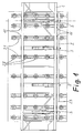
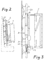
- FIGS 1 to 3 show a plate gripper of a stacking device, wherein for the sake of simplicity, the movable arm of the stacking device and the pivoting device which connects the arm to the plate gripper are not shown.
- the illustrated Plate gripper consists of a suction cross 1 and a suction frame 2, wherein the suction cross member forms the support frame for the suction frame.
- the suction frame 2 in turn consists of a number of vertical suction bars 21, which in turn each carry a number of suckers 22 and are connected together in their lower region by a crossbar 23.
- the suction frame 2 is guided vertically movable in the Saugtraverse 1 by the suction bars 21 are guided in each case in upper and lower guides 11 of the suction cross member.
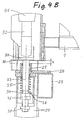
- FIGS. 4A and 4B fragments of the suction cross member 1 are visible, as well as a lowering member 3 mounted therein. Also visible in these figures are fragments of the suction frame 2 which is movable relative to the suction cross member 1, namely the cross bar 23 connecting all suction bars and one of the suction bars 21 In the region of each lowering element 3, the transverse bar 23 is firmly connected to a plate 24 and a sleeve 25, which therefore likewise embody parts of the suction frame 2 movable relative to the suction crossbar 1.
- Each Absenkorgan consists of an electric cylinder 31 with a stroke of, for example, about 200 mm.
- the lifting spindle 32 of each electric cylinder 31 carries a support sleeve 34 via a rod 33.
- a strong compression spring 35 is installed between the support sleeve 34 and the sleeve 25, over which the suction frame 2 now projects over the transverse bar 23, the plate 24 in the area of the respective lowering element and the sleeve 25 is supported on the support sleeve 34.
- the lower portion of the rod 33 is formed as a threaded rod and carries two adjusting nuts, namely an upper adjusting nut 36 and a lower adjusting nut 37.
- the springs 35 of all Absenkorgane are dimensioned and adjusted so that the sum of the spring pressure forces is slightly smaller than the weight of the suction frame 2. This has the consequence that in the vertical position of the plate gripper, as shown in Figures 1 to 3, the approximately vertically downward weight force of the suction frame 2 just exceeds the sum of the spring pressure forces of the compression springs 35 and causes the suction frame. 2 compresses these springs, so that the sleeve 25 is seated on the support sleeve 24 on each lowering member 3.
- the sleeve 25 is located above said support sleeve 34 by said distance x. This is the position as shown in FIG. 4A. In this position, the plate gripper picks up a glass plate to be stacked from the conveyor line, lifts it from this and then pivots it in the approximately vertical position, as shown in Figures 2 and 3.
- the electric cylinder 31 of the Absenkorgane 3 synchronously operated and drive the lifting spindles 32 from.
- the electric cylinder 31 of the Absenkorgane 3 synchronously operated and drive the lifting spindles 32 from.
- a attached to the plate 24 Organ 30 of a proximity switch reports this lift-off movement, which causes the immediate shutdown of the electric cylinder, so that the actual lift-off only makes up a fraction of the distance x.
- the distance x can be adjusted by means of the lower adjusting nut 37 by adjusting the axial position of the supporting sleeve 34 on the rod 33.
- the suction frame Since the weight of the suction frame in the approximately vertical position of the plate gripper, as I said, is slightly greater than the sum of the compressive forces of the springs 35, the suction frame remains even after blowing off the glass plate still resting on the support sleeves 34 and is not pushed upwards at the same time.
- the stacking of the glass plates is done in the following way:
- the electric cylinders are fully retracted, and the plate gripper moves the glass plate over the stacking stand until the lower edge The glass plate is about 80 mm above the frame contact surfaces. Then, the electric cylinders are operated to lower the glass plate. When the glass plate sits on the frame, the current extension position is automatically saved when the electric cylinder is stopped.
- the electric cylinders then return to their normal position.
- the electric cylinders When stacking the following plates of a package but then move the electric cylinder equal to each stored in the previous settling position minus a distance of about 10 to 20 mm, so that then the final lowering movement is only about 10 to 20 mm.
Landscapes
- Sheets, Magazines, And Separation Thereof (AREA)
- Re-Forming, After-Treatment, Cutting And Transporting Of Glass Products (AREA)
- Handcart (AREA)
Claims (8)
- Dispositif pour abaisser des plaques de verre sur des casiers de stockage, qui est disposé entre le palonnier à vide (1) d'un préhenseur de plaques et le cadre à vide (2) porté par ledit préhenseur de plaques et guidé de façon mobile verticalement par rapport à celui-ci et qui comprend au moins un organe d'abaissement (3), comportant les caractéristiques suivantes :a) chaque organe d'abaissement (3) présente un élément de levage déplaçable (32) qui présente à son extrémité libre un élément porteur (34) pour supporter le cadre à vide (2),b) le cadre à vide est maintenu sur l'élément de levage (32) de façon mobile verticalement d'une certaine distance courte (x),c) entre l'élément porteur (34) et le cadre à vide (2) est monté un ressort de pression, la somme des forces élastiques des ressorts de pression de tous les organes d'abaissement existants (3) étant supérieure au poids propre du cadre à vide,d) la distance de déplacement verticale (x) entre le cadre à vide (2) et l'élément de levage (32) est fixée par une butée supérieure entre l'élément de levage et le cadre à vide et une butée inférieure entre le cadre à vide et l'extrémité supérieure de l'élément porteur (34) sur lequel le cadre à vide peut reposer en comprimant partiellement le ressort de pression (35).
- Dispositif selon la revendication 1, chaque organe de levage étant formé par un vérin électrique (31) avec tige de levage (32).
- Dispositif selon la revendication 1 ou 2, la distance de déplacement possible (x) entre l'élément de levage (32) et le cadre à vide (2) étant réglable par possibilité de réglage (36) de la position axiale de l'élément porteur (34) à l'extrémité libre de l'élément de levage (32).
- Dispositif selon l'une des revendications 1 à 3, la force élastique du ressort de pression (35) étant ajustable par possibilité d'ajustage axial (37) d'une butée de ressort (38).
- Dispositif selon l'une des revendications 1 à 4, l'extrémité inférieure libre de l'élément de levage (32) étant formée par une tige porteuse (33) à l'extrémité inférieure de laquelle l'élément porteur (34) en forme de douille ou de godet est monté et sur laquelle le ressort de pression (35) est disposé en tant que ressort en spirale.
- Dispositif selon les revendications 4 et 5, l'extrémité inférieure de la tige porteuse (32) étant conçue comme une tige filetée qui présente, à l'intérieur de l'élément porteur (34) en forme de douille ou de godet, un écrou de réglage (37) servant à régler la position axiale d'une cuvette de ressort (38) et, au-dessous de l'élément porteur (34), un écrou de réglage (37) servant à régler la position axiale de l'élément porteur (34).
- Dispositif selon l'une des revendications 1 à 6, un capteur (30) destiné à détecter un mouvement relatif entre le cadre à vide (2) et l'élément de levage (32) étant prévu.
- Dispositif selon la revendication 7, le capteur étant conçu comme un détecteur de proximité qui signale un soulèvement du cadre à vide (2) à partir de la position dans laquelle il repose sur l'élément porteur (34).
Applications Claiming Priority (2)
| Application Number | Priority Date | Filing Date | Title |
|---|---|---|---|
| DE10236775 | 2002-08-10 | ||
| DE10236775A DE10236775A1 (de) | 2002-08-10 | 2002-08-10 | Einrichtung zum Absenken von Glasplatten auf Stapelgestelle |
Publications (3)
| Publication Number | Publication Date |
|---|---|
| EP1388511A2 EP1388511A2 (fr) | 2004-02-11 |
| EP1388511A3 EP1388511A3 (fr) | 2004-08-25 |
| EP1388511B1 true EP1388511B1 (fr) | 2006-07-12 |
Family
ID=30128822
Family Applications (1)
| Application Number | Title | Priority Date | Filing Date |
|---|---|---|---|
| EP03004574A Expired - Lifetime EP1388511B1 (fr) | 2002-08-10 | 2003-02-28 | Méchanisme pour abaisser des feuilles de verre sur un casier de stockage |
Country Status (4)
| Country | Link |
|---|---|
| EP (1) | EP1388511B1 (fr) |
| AT (1) | ATE332861T1 (fr) |
| DE (2) | DE10236775A1 (fr) |
| ES (1) | ES2268183T3 (fr) |
Families Citing this family (5)
| Publication number | Priority date | Publication date | Assignee | Title |
|---|---|---|---|---|
| ITPD20050044A1 (it) * | 2005-02-18 | 2006-08-19 | Alessandro Piazza | Attrezzatura per la movimentazione di prodotti lastriformi in cassa, in pacco e di singoli prodotti lastriformi |
| CN102874598B (zh) * | 2012-09-06 | 2016-04-20 | 东莞市威力固电路板设备有限公司 | 基板投放方法 |
| CN102963578B (zh) * | 2012-11-23 | 2015-07-01 | 深圳市华星光电技术有限公司 | 面板解包方法及解包装置 |
| CN104097950B (zh) * | 2013-04-08 | 2016-06-08 | 常州亚玛顿股份有限公司 | 玻璃运输装置 |
| CN106629058B (zh) * | 2016-12-07 | 2023-11-21 | 中国建材国际工程集团有限公司 | 从玻璃板下表面抓取玻璃的吸盘装置及控制方法 |
Family Cites Families (5)
| Publication number | Priority date | Publication date | Assignee | Title |
|---|---|---|---|---|
| FR2012911A1 (en) * | 1968-07-12 | 1970-03-27 | Werner Joh | Positioning or lifting glass onto a carriage |
| FR2061502A1 (fr) * | 1969-02-13 | 1971-06-25 | Saint Gobain | |
| DE2357118A1 (de) * | 1973-11-15 | 1975-05-28 | Matthias Dipl Ing Kiwull | Kippbarer tisch mit ablagegestell fuer die aufnahme und weitergabe von platten, insbesondere isolierglasscheiben |
| IT232710Y1 (it) * | 1994-01-27 | 2000-01-19 | Breton Automazioni Spa | Apparecchiatura perfezionata per il carico e lo scarico di lastre di materiale lapideo da una macchina operatrice. |
| IT1303348B1 (it) * | 1998-08-24 | 2000-11-06 | For El Base Di Vianello Fortun | Macchina automatica o semiautomatica per il prelievo delle lastre divetro, o di materiali diversi, da un magazzino e l'alimentazione di |
-
2002
- 2002-08-10 DE DE10236775A patent/DE10236775A1/de not_active Withdrawn
-
2003
- 2003-02-28 DE DE50304192T patent/DE50304192D1/de not_active Expired - Lifetime
- 2003-02-28 EP EP03004574A patent/EP1388511B1/fr not_active Expired - Lifetime
- 2003-02-28 ES ES03004574T patent/ES2268183T3/es not_active Expired - Lifetime
- 2003-02-28 AT AT03004574T patent/ATE332861T1/de not_active IP Right Cessation
Also Published As
| Publication number | Publication date |
|---|---|
| ATE332861T1 (de) | 2006-08-15 |
| EP1388511A3 (fr) | 2004-08-25 |
| DE10236775A1 (de) | 2004-02-19 |
| DE50304192D1 (de) | 2006-08-24 |
| EP1388511A2 (fr) | 2004-02-11 |
| ES2268183T3 (es) | 2007-03-16 |
Similar Documents
| Publication | Publication Date | Title |
|---|---|---|
| DE2534819C2 (de) | Vorrichtung zum Entstapeln und Transportieren von Platinen | |
| DE3800907C2 (de) | Verfahren zur Entstapelung von Blechen | |
| EP0423065A2 (fr) | Déchargeur de piles des feuilles pour enlever une section de pile d'une pile des feuilles | |
| EP1724078B1 (fr) | Dispositif pour pousser une section de pile avec au moins une pièce en forme de plaque d'une pile restante | |
| DE3730126A1 (de) | System zum automatischen verladen von glasscheiben-erzeugnissen eines nach dem anderen auf einer palette | |
| DE4305826A1 (de) | Verfahren und Vorrichtung zum Zerteilen von Glastafeln in Zuschnitte | |
| DE3414996C1 (de) | Vorrichtung zum Abschieben von auf einer Trageinrichtung abgelegten Stapeln oder Paketen | |
| DE29701967U1 (de) | Vorrichtung zum Abschneiden von Stahl | |
| EP1873095A2 (fr) | Dispositif de séparation, en particulier d'enlèvement d'une partie de la pile dotée d'au moins une plaque de grand format d'une pile résiduelle dotée de plusieurs plaques de grand format | |
| DE19632289A1 (de) | Verfahren und Vorrichtung zur Aufnahme aufeinander gestapelter Materialbögen | |
| DE2505530C3 (de) | Vorrichtung an kontinuierlich arbeitenden Bogenanlegern zur Kompensation der sich beim Stapelwechsel durch das seitliche Herausziehen des Hilfsstapeltisches auf der Oberseite des HilfsStapels fortschreitend bildenden Absenkung | |
| DE4320397C2 (de) | Einrichtung zum Beschicken von Werkzeugmaschinen | |
| EP0361126A1 (fr) | Scie pour le débitage des plaques | |
| AT396891B (de) | Einrichtung zum beschicken von aufteilsägeanlagen | |
| DE68902412T2 (de) | Hebevorrichtung mit sauggreifen. | |
| EP1388511A2 (fr) | Méchanisme pour abaisser des feuilles de verre sur un casier de stockage | |
| DE69309506T2 (de) | Vorrichtung zum automatischen Beladen von Platten | |
| EP0640529A1 (fr) | Dispositif pour banderoler des produits d'imprimerie | |
| DE4401510C2 (de) | Vorrichtung zur Bildung eines Stapels aus aneinanderlehnenden, hochkantstehenden Platten | |
| CH672284A5 (fr) | ||
| EP0226008B1 (fr) | Récipient pour l'empilage des pièces en tôle, notamment pour la fabrication de boîtes | |
| DE2505282A1 (de) | Vorrichtung zum vereinzeln von aufgestauten foerderlingen | |
| EP0745726A2 (fr) | Calandre pour le satinage ou semi-satinage du papier | |
| AT331721B (de) | Einrichtung zur aufnahme und weitergabe bzw. zum abstapeln plattenformiger werkstucke | |
| DE2852957A1 (de) | Vorrichtung zum selbsttaetigen stapeln von werkstuecken |
Legal Events
| Date | Code | Title | Description |
|---|---|---|---|
| PUAI | Public reference made under article 153(3) epc to a published international application that has entered the european phase |
Free format text: ORIGINAL CODE: 0009012 |
|
| AK | Designated contracting states |
Kind code of ref document: A2 Designated state(s): AT BE BG CH CY CZ DE DK EE ES FI FR GB GR HU IE IT LI LU MC NL PT SE SI SK TR |
|
| AX | Request for extension of the european patent |
Extension state: AL LT LV MK RO |
|
| PUAL | Search report despatched |
Free format text: ORIGINAL CODE: 0009013 |
|
| AK | Designated contracting states |
Kind code of ref document: A3 Designated state(s): AT BE BG CH CY CZ DE DK EE ES FI FR GB GR HU IE IT LI LU MC NL PT SE SI SK TR |
|
| AX | Request for extension of the european patent |
Extension state: AL LT LV MK RO |
|
| 17P | Request for examination filed |
Effective date: 20050216 |
|
| AKX | Designation fees paid |
Designated state(s): AT BE BG CH CY CZ DE DK EE ES FI FR GB GR HU IE IT LI LU MC NL PT SE SI SK TR |
|
| 17Q | First examination report despatched |
Effective date: 20050620 |
|
| GRAP | Despatch of communication of intention to grant a patent |
Free format text: ORIGINAL CODE: EPIDOSNIGR1 |
|
| GRAS | Grant fee paid |
Free format text: ORIGINAL CODE: EPIDOSNIGR3 |
|
| GRAA | (expected) grant |
Free format text: ORIGINAL CODE: 0009210 |
|
| AK | Designated contracting states |
Kind code of ref document: B1 Designated state(s): AT BE BG CH CY CZ DE DK EE ES FI FR GB GR HU IE IT LI LU MC NL PT SE SI SK TR |
|
| PG25 | Lapsed in a contracting state [announced via postgrant information from national office to epo] |
Ref country code: SI Free format text: LAPSE BECAUSE OF FAILURE TO SUBMIT A TRANSLATION OF THE DESCRIPTION OR TO PAY THE FEE WITHIN THE PRESCRIBED TIME-LIMIT Effective date: 20060712 Ref country code: IT Free format text: LAPSE BECAUSE OF FAILURE TO SUBMIT A TRANSLATION OF THE DESCRIPTION OR TO PAY THE FEE WITHIN THE PRESCRIBED TIME-LIMIT;WARNING: LAPSES OF ITALIAN PATENTS WITH EFFECTIVE DATE BEFORE 2007 MAY HAVE OCCURRED AT ANY TIME BEFORE 2007. THE CORRECT EFFECTIVE DATE MAY BE DIFFERENT FROM THE ONE RECORDED. Effective date: 20060712 Ref country code: NL Free format text: LAPSE BECAUSE OF FAILURE TO SUBMIT A TRANSLATION OF THE DESCRIPTION OR TO PAY THE FEE WITHIN THE PRESCRIBED TIME-LIMIT Effective date: 20060712 Ref country code: IE Free format text: LAPSE BECAUSE OF FAILURE TO SUBMIT A TRANSLATION OF THE DESCRIPTION OR TO PAY THE FEE WITHIN THE PRESCRIBED TIME-LIMIT Effective date: 20060712 Ref country code: SK Free format text: LAPSE BECAUSE OF FAILURE TO SUBMIT A TRANSLATION OF THE DESCRIPTION OR TO PAY THE FEE WITHIN THE PRESCRIBED TIME-LIMIT Effective date: 20060712 Ref country code: FI Free format text: LAPSE BECAUSE OF FAILURE TO SUBMIT A TRANSLATION OF THE DESCRIPTION OR TO PAY THE FEE WITHIN THE PRESCRIBED TIME-LIMIT Effective date: 20060712 |
|
| REG | Reference to a national code |
Ref country code: GB Ref legal event code: FG4D Free format text: NOT ENGLISH |
|
| REG | Reference to a national code |
Ref country code: CH Ref legal event code: EP |
|
| REG | Reference to a national code |
Ref country code: IE Ref legal event code: FG4D Free format text: LANGUAGE OF EP DOCUMENT: GERMAN |
|
| REF | Corresponds to: |
Ref document number: 50304192 Country of ref document: DE Date of ref document: 20060824 Kind code of ref document: P |
|
| GBT | Gb: translation of ep patent filed (gb section 77(6)(a)/1977) |
Effective date: 20060830 |
|
| PG25 | Lapsed in a contracting state [announced via postgrant information from national office to epo] |
Ref country code: BG Free format text: LAPSE BECAUSE OF FAILURE TO SUBMIT A TRANSLATION OF THE DESCRIPTION OR TO PAY THE FEE WITHIN THE PRESCRIBED TIME-LIMIT Effective date: 20061012 Ref country code: DK Free format text: LAPSE BECAUSE OF FAILURE TO SUBMIT A TRANSLATION OF THE DESCRIPTION OR TO PAY THE FEE WITHIN THE PRESCRIBED TIME-LIMIT Effective date: 20061012 |
|
| REG | Reference to a national code |
Ref country code: SE Ref legal event code: TRGR |
|
| PG25 | Lapsed in a contracting state [announced via postgrant information from national office to epo] |
Ref country code: PT Free format text: LAPSE BECAUSE OF FAILURE TO SUBMIT A TRANSLATION OF THE DESCRIPTION OR TO PAY THE FEE WITHIN THE PRESCRIBED TIME-LIMIT Effective date: 20061212 |
|
| NLV1 | Nl: lapsed or annulled due to failure to fulfill the requirements of art. 29p and 29m of the patents act | ||
| ET | Fr: translation filed | ||
| REG | Reference to a national code |
Ref country code: IE Ref legal event code: FD4D |
|
| PG25 | Lapsed in a contracting state [announced via postgrant information from national office to epo] |
Ref country code: MC Free format text: LAPSE BECAUSE OF NON-PAYMENT OF DUE FEES Effective date: 20070228 Ref country code: LI Free format text: LAPSE BECAUSE OF NON-PAYMENT OF DUE FEES Effective date: 20070228 Ref country code: CH Free format text: LAPSE BECAUSE OF NON-PAYMENT OF DUE FEES Effective date: 20070228 |
|
| REG | Reference to a national code |
Ref country code: ES Ref legal event code: FG2A Ref document number: 2268183 Country of ref document: ES Kind code of ref document: T3 |
|
| PLBE | No opposition filed within time limit |
Free format text: ORIGINAL CODE: 0009261 |
|
| STAA | Information on the status of an ep patent application or granted ep patent |
Free format text: STATUS: NO OPPOSITION FILED WITHIN TIME LIMIT |
|
| 26N | No opposition filed |
Effective date: 20070413 |
|
| REG | Reference to a national code |
Ref country code: CH Ref legal event code: PL |
|
| PG25 | Lapsed in a contracting state [announced via postgrant information from national office to epo] |
Ref country code: GR Free format text: LAPSE BECAUSE OF FAILURE TO SUBMIT A TRANSLATION OF THE DESCRIPTION OR TO PAY THE FEE WITHIN THE PRESCRIBED TIME-LIMIT Effective date: 20061013 |
|
| PG25 | Lapsed in a contracting state [announced via postgrant information from national office to epo] |
Ref country code: AT Free format text: LAPSE BECAUSE OF NON-PAYMENT OF DUE FEES Effective date: 20070228 |
|
| PG25 | Lapsed in a contracting state [announced via postgrant information from national office to epo] |
Ref country code: EE Free format text: LAPSE BECAUSE OF FAILURE TO SUBMIT A TRANSLATION OF THE DESCRIPTION OR TO PAY THE FEE WITHIN THE PRESCRIBED TIME-LIMIT Effective date: 20060712 |
|
| PG25 | Lapsed in a contracting state [announced via postgrant information from national office to epo] |
Ref country code: CY Free format text: LAPSE BECAUSE OF FAILURE TO SUBMIT A TRANSLATION OF THE DESCRIPTION OR TO PAY THE FEE WITHIN THE PRESCRIBED TIME-LIMIT Effective date: 20060712 |
|
| PG25 | Lapsed in a contracting state [announced via postgrant information from national office to epo] |
Ref country code: HU Free format text: LAPSE BECAUSE OF FAILURE TO SUBMIT A TRANSLATION OF THE DESCRIPTION OR TO PAY THE FEE WITHIN THE PRESCRIBED TIME-LIMIT Effective date: 20070113 Ref country code: TR Free format text: LAPSE BECAUSE OF FAILURE TO SUBMIT A TRANSLATION OF THE DESCRIPTION OR TO PAY THE FEE WITHIN THE PRESCRIBED TIME-LIMIT Effective date: 20060712 |
|
| REG | Reference to a national code |
Ref country code: FR Ref legal event code: PLFP Year of fee payment: 14 |
|
| REG | Reference to a national code |
Ref country code: FR Ref legal event code: PLFP Year of fee payment: 15 |
|
| REG | Reference to a national code |
Ref country code: FR Ref legal event code: PLFP Year of fee payment: 16 |
|
| PGFP | Annual fee paid to national office [announced via postgrant information from national office to epo] |
Ref country code: GB Payment date: 20220221 Year of fee payment: 20 Ref country code: DE Payment date: 20220217 Year of fee payment: 20 |
|
| PGFP | Annual fee paid to national office [announced via postgrant information from national office to epo] |
Ref country code: SE Payment date: 20220221 Year of fee payment: 20 Ref country code: LU Payment date: 20220214 Year of fee payment: 20 Ref country code: IT Payment date: 20220228 Year of fee payment: 20 Ref country code: FR Payment date: 20220221 Year of fee payment: 20 Ref country code: ES Payment date: 20220318 Year of fee payment: 20 Ref country code: CZ Payment date: 20220228 Year of fee payment: 20 Ref country code: BE Payment date: 20220216 Year of fee payment: 20 |
|
| REG | Reference to a national code |
Ref country code: DE Ref legal event code: R082 Ref document number: 50304192 Country of ref document: DE Representative=s name: FLEUCHAUS & GALLO PARTNERSCHAFT MBB PATENTANWA, DE |
|
| REG | Reference to a national code |
Ref country code: DE Ref legal event code: R071 Ref document number: 50304192 Country of ref document: DE |
|
| REG | Reference to a national code |
Ref country code: BE Ref legal event code: MK Effective date: 20230228 |
|
| REG | Reference to a national code |
Ref country code: GB Ref legal event code: PE20 Expiry date: 20230227 |
|
| REG | Reference to a national code |
Ref country code: SE Ref legal event code: EUG |
|
| PG25 | Lapsed in a contracting state [announced via postgrant information from national office to epo] |
Ref country code: CZ Free format text: LAPSE BECAUSE OF EXPIRATION OF PROTECTION Effective date: 20230228 |
|
| REG | Reference to a national code |
Ref country code: ES Ref legal event code: FD2A Effective date: 20230428 |
|
| PG25 | Lapsed in a contracting state [announced via postgrant information from national office to epo] |
Ref country code: GB Free format text: LAPSE BECAUSE OF EXPIRATION OF PROTECTION Effective date: 20230227 |
|
| PG25 | Lapsed in a contracting state [announced via postgrant information from national office to epo] |
Ref country code: ES Free format text: LAPSE BECAUSE OF EXPIRATION OF PROTECTION Effective date: 20230301 |