EP1388618A1 - Dispositif d'écoulement - Google Patents
Dispositif d'écoulement Download PDFInfo
- Publication number
- EP1388618A1 EP1388618A1 EP03016125A EP03016125A EP1388618A1 EP 1388618 A1 EP1388618 A1 EP 1388618A1 EP 03016125 A EP03016125 A EP 03016125A EP 03016125 A EP03016125 A EP 03016125A EP 1388618 A1 EP1388618 A1 EP 1388618A1
- Authority
- EP
- European Patent Office
- Prior art keywords
- drain
- connection
- spout
- clip
- pot
- Prior art date
- Legal status (The legal status is an assumption and is not a legal conclusion. Google has not performed a legal analysis and makes no representation as to the accuracy of the status listed.)
- Granted
Links
- XLYOFNOQVPJJNP-UHFFFAOYSA-N water Substances O XLYOFNOQVPJJNP-UHFFFAOYSA-N 0.000 claims abstract description 6
- 239000000463 material Substances 0.000 claims description 5
- 239000002184 metal Substances 0.000 claims description 3
- 239000002699 waste material Substances 0.000 description 4
- 238000007789 sealing Methods 0.000 description 2
- 101150114468 TUB1 gene Proteins 0.000 description 1
- 230000004888 barrier function Effects 0.000 description 1
- 238000012423 maintenance Methods 0.000 description 1
Images
Classifications
-
- E—FIXED CONSTRUCTIONS
- E03—WATER SUPPLY; SEWERAGE
- E03C—DOMESTIC PLUMBING INSTALLATIONS FOR FRESH WATER OR WASTE WATER; SINKS
- E03C1/00—Domestic plumbing installations for fresh water or waste water; Sinks
- E03C1/12—Plumbing installations for waste water; Basins or fountains connected thereto; Sinks
- E03C1/22—Outlet devices mounted in basins, baths, or sinks
- E03C1/23—Outlet devices mounted in basins, baths, or sinks with mechanical closure mechanisms
- E03C1/2304—Outlet devices mounted in basins, baths, or sinks with mechanical closure mechanisms the actuation force being transmitted to the plug via flexible elements, e.g. chain, Bowden cable
-
- E—FIXED CONSTRUCTIONS
- E03—WATER SUPPLY; SEWERAGE
- E03C—DOMESTIC PLUMBING INSTALLATIONS FOR FRESH WATER OR WASTE WATER; SINKS
- E03C1/00—Domestic plumbing installations for fresh water or waste water; Sinks
- E03C1/12—Plumbing installations for waste water; Basins or fountains connected thereto; Sinks
- E03C1/22—Outlet devices mounted in basins, baths, or sinks
- E03C1/23—Outlet devices mounted in basins, baths, or sinks with mechanical closure mechanisms
- E03C2001/2315—Outlet devices mounted in basins, baths, or sinks with mechanical closure mechanisms the actuation force created by a turning movement of a handle
Definitions
- the present invention relates to a waste fitting according to the preamble of Claim 1.
- drain fittings especially for bathtubs, where at a drain opening a tub, a closable valve is provided, which has a Actuating mechanism is movable and above a drain pot with odor barrier is arranged.
- a drain pot made of plastic is another Connection for a circulation circuit, provided for example for a whirlpool, so that from the circulation circuit via a connection a residual water discharge can be done in the drain pot.
- Problematic with such drain fittings is the connection of the circulation system to the drain pot, since this Area under the tub is difficult to access. Through permanently installed thread or clamping connections there is the problem that a subsequent Disassembly for maintenance is hardly possible.
- connection at the other connection of the drain fitting a spout for Connection with a residual water line clamped.
- the connection can be realized in a detachable manner in the manner of a quick-release closure, where the spout is simply plugged into the port.
- the Grommet be designed as a simple rotary part, so that the type of connection flexible can be designed.
- the spout is fixed by means of a clip on the connection.
- the clip also provides a safeguard against unintentional Pulling out of the spout dar.
- the spout of the clip embraced be, with the clips is inserted into a slot in the terminal.
- the spout has a cylindrical portion which sealed in the connector is inserted. Further, preferably on the cylindrical Section a groove for engagement with the clip recessed, so that a substantially positive connection in the axial direction between the nozzle and connection is provided.
- the clip may have two legs in the manner of a latching connection, the grasp the spout by just over halfway.
- the clip can be stuck when plugging something wide, so that it can be locked in a simple manner. Therefor can also be provided on the legs of the clip splayed ends.
- the spout is preferably made of a different material than the terminal, for example made of metal, so that at the section outside the terminal of the Drain fitting different connection options can be realized.
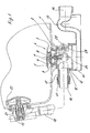
- a drain fitting is mounted on a trough 1, on the bottom side a drain opening 2 is provided.
- a drain 3 is arranged, the can be closed by means of a valve 4.
- the valve 4 comprises a cap 5, on which a sealing element 6 is provided, the can achieve a seal with the drain 3.
- the cap 5 is on a sleeve 7 mounted, in which a screw 8 is screwed.
- the sleeve 7 is in the vertical direction in a mounted on the drain 3 recording 9 out.
- the drain 3 opens into a flow element 10, which with a drain pot 11th connected is.
- the passage element 10 is sealed by a seal 12 in held the drain pot 11, wherein the flow element 10 via a latching device in the drain pot 11 can be inserted.
- the drain pot has a siphon-like Deflection 13, which in a port 14 for a not shown drain pipe empties.
- the passage element 10 has a connection 15 into which a pipe 16 is set tightly over a nut 17.
- the tube 16 is over a curvature with a pipe 18 which is connected to an overflow element 19.
- the Overflow element 19 is adjacent to an opening 21 in a side wall of Trough 1 arranged.
- a knob 22 is also an actuator intended for the waste set.
- the operation of the drain set via the knob 22, which has a Bowden cable, not shown, is connected to a bolt 20.
- the bolt 20 has a lever 21 which is also connected to the Bowden cable, so that a rotation of the knob 22 is transmitted to the bolt 20.
- a lever 24 having a portion 25 in a recess of the bolt 20 fixed, wherein the lever 24 by a rotational movement of the bolt 20th the valve 4 can move in the vertical direction for opening and closing.
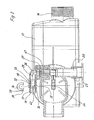
- a rotary valve 27 on a cylindrical portion 26 rotatably mounted, wherein the rotary valve 27 rotatably mounted in a seal 47 is.
- a flow channel is formed, which forms a bow 29 adjacent to a port 30 to a drain channel 28 connect can.
- valve 4 When valve 4 is open, there is also a connection between the connection 30 and the drainage channel 28 made while the valve 4 is closed Rotary valve 27 is also closed by means of the bolt 20.
- the terminal 30 is formed substantially cylindrical and serves for receiving a spout 31.
- the spout 31 has a cylindrical portion 32 on which a front groove is recessed, in which a sealing ring 33 is inserted, the clamping at the terminal 30 is present. Further, on the cylindrical portion 32 a slightly thickened Section provided in which a further groove 42 is recessed. In the groove 42 a clip 34 is inserted, which has two legs 38, the spout 31 to surrounded by more than half the circumference. The clip 34 is elastic and has spread ends 39, which in the manner of a snap closure on the Grommet 31 can be plugged. This is at a front portion 35th of the terminal 30 recessed a slot, so that the clips 34, the spout 31 in the axial direction guaranteed.
- the spout 31 further includes a shoulder 36 which serves as a stop against the end edge of the terminal 30 is applied.
- the spout 31 has a portion 37, the Connection to an unillustrated circulation system is used.
- the section 37 Can be used as a threaded section, compressible section or other as required Art connectable section be made to allow the piping system connected can be.
- For mounting only the spout 31 in the connection 30 are inserted and secured over the clips 34. This can even in confined spaces below the tub 1 done.
- For disassembly is only the clip 34 is grasped and pulled out, after which the spout 31st can be removed from the terminal 30.
- the drain fitting with the flow element 10 and the drain pot 11 is preferably made of plastic, while the spout 31 made of a different material may be formed, in particular a rotatable material, like metal. However, other materials can be used.
- a locking connection be used, for example, if molded to the housing lips engage in appropriate receptacles on the spout to set this.
Landscapes
- Engineering & Computer Science (AREA)
- Mechanical Engineering (AREA)
- Environmental & Geological Engineering (AREA)
- Health & Medical Sciences (AREA)
- Life Sciences & Earth Sciences (AREA)
- Hydrology & Water Resources (AREA)
- Public Health (AREA)
- Water Supply & Treatment (AREA)
- Sink And Installation For Waste Water (AREA)
Applications Claiming Priority (2)
| Application Number | Priority Date | Filing Date | Title |
|---|---|---|---|
| DE20212292U DE20212292U1 (de) | 2002-08-09 | 2002-08-09 | Ablaufgarnitur |
| DE20212292U | 2002-08-09 |
Publications (2)
| Publication Number | Publication Date |
|---|---|
| EP1388618A1 true EP1388618A1 (fr) | 2004-02-11 |
| EP1388618B1 EP1388618B1 (fr) | 2007-06-13 |
Family
ID=29796695
Family Applications (1)
| Application Number | Title | Priority Date | Filing Date |
|---|---|---|---|
| EP03016125A Expired - Lifetime EP1388618B1 (fr) | 2002-08-09 | 2003-07-16 | Dispositif d'écoulement |
Country Status (3)
| Country | Link |
|---|---|
| EP (1) | EP1388618B1 (fr) |
| DE (2) | DE20212292U1 (fr) |
| ES (1) | ES2286361T3 (fr) |
Cited By (1)
| Publication number | Priority date | Publication date | Assignee | Title |
|---|---|---|---|---|
| EP4279669A1 (fr) | 2022-05-19 | 2023-11-22 | BLANCO GmbH + Co KG | Dispositif d'écoulement pour un bassin |
Families Citing this family (3)
| Publication number | Priority date | Publication date | Assignee | Title |
|---|---|---|---|---|
| DE202004008315U1 (de) * | 2004-05-25 | 2005-10-06 | Viega Gmbh & Co. Kg | Ablauf |
| NL1032083C2 (nl) * | 2006-06-29 | 2008-01-02 | Easy Sanitairy Solutions Bv | Platte afvoer. |
| DE202011106651U1 (de) * | 2011-10-12 | 2013-01-16 | Viega Gmbh & Co. Kg | Ablaufgarnitur mit Wechselventil für Whirlpool-Wannen |
Citations (4)
| Publication number | Priority date | Publication date | Assignee | Title |
|---|---|---|---|---|
| GB2217986A (en) * | 1988-04-05 | 1989-11-08 | John Murfin | Whirlpool/spa bath drainage valve |
| EP0421520A2 (fr) * | 1989-10-03 | 1991-04-10 | TEUCO GUZZINI S.r.l. | Drainage, spécialement pour bains avec systèmes de hydromassage |
| US5857718A (en) * | 1995-05-11 | 1999-01-12 | Benteler Ag | Arrangement for connecting a metal pipe to a receiving sleeve |
| EP1143078A1 (fr) * | 2000-04-06 | 2001-10-10 | Friedrich Grohe AG & Co. KG | Bec rotatif pour robinet |
Family Cites Families (2)
| Publication number | Priority date | Publication date | Assignee | Title |
|---|---|---|---|---|
| DE10005660A1 (de) * | 1999-02-09 | 2001-03-15 | Kurt Michael Desch | Ablaufgarnitur mit Badewannenwasser-Ableitung über einem tiefergelegten Verschlußstopfen und vorzugsweise mit Unterniveau-Mischwasser-Zufluß, gegen Rücksaugen abgesichert mittels freier Fließstrecke |
| DE10038246B4 (de) * | 1999-08-10 | 2005-12-15 | Desch, Kurt Michael, Dipl.-Ing. (FH) | Badewannen Überlaufgarnitur mit horizontalem Wannenüberlauf |
-
2002
- 2002-08-09 DE DE20212292U patent/DE20212292U1/de not_active Expired - Lifetime
-
2003
- 2003-07-16 EP EP03016125A patent/EP1388618B1/fr not_active Expired - Lifetime
- 2003-07-16 DE DE50307449T patent/DE50307449D1/de not_active Expired - Lifetime
- 2003-07-16 ES ES03016125T patent/ES2286361T3/es not_active Expired - Lifetime
Patent Citations (4)
| Publication number | Priority date | Publication date | Assignee | Title |
|---|---|---|---|---|
| GB2217986A (en) * | 1988-04-05 | 1989-11-08 | John Murfin | Whirlpool/spa bath drainage valve |
| EP0421520A2 (fr) * | 1989-10-03 | 1991-04-10 | TEUCO GUZZINI S.r.l. | Drainage, spécialement pour bains avec systèmes de hydromassage |
| US5857718A (en) * | 1995-05-11 | 1999-01-12 | Benteler Ag | Arrangement for connecting a metal pipe to a receiving sleeve |
| EP1143078A1 (fr) * | 2000-04-06 | 2001-10-10 | Friedrich Grohe AG & Co. KG | Bec rotatif pour robinet |
Cited By (2)
| Publication number | Priority date | Publication date | Assignee | Title |
|---|---|---|---|---|
| EP4279669A1 (fr) | 2022-05-19 | 2023-11-22 | BLANCO GmbH + Co KG | Dispositif d'écoulement pour un bassin |
| DE102022205026A1 (de) | 2022-05-19 | 2023-11-23 | Blanco Gmbh + Co Kg | Ablaufvorrichtung für ein Becken |
Also Published As
| Publication number | Publication date |
|---|---|
| EP1388618B1 (fr) | 2007-06-13 |
| ES2286361T3 (es) | 2007-12-01 |
| DE50307449D1 (de) | 2007-07-26 |
| DE20212292U1 (de) | 2003-12-18 |
Similar Documents
| Publication | Publication Date | Title |
|---|---|---|
| EP0476402B1 (fr) | Dispositif de fixation d'une pomme de douche | |
| EP0787864A1 (fr) | Dispositif de sécurité sanitair | |
| EP4437192A1 (fr) | Accessoire, article de meuble de salle de bains ou de cuisine comprenant ledit accessoire, et procédé d'ouverture et de fermeture d'une vidange dans un article de meuble de salle de bains ou de cuisine | |
| EP1707692B1 (fr) | Robinet pourvu d'un bec téléscopique | |
| EP1388618B1 (fr) | Dispositif d'écoulement | |
| EP3988724B1 (fr) | Dispositif d'admission, corps de baignoire et procédé | |
| DE102007009409B4 (de) | Armatur mit Schwenkauslauf | |
| EP0845559B1 (fr) | Dispositif de trop-plein pour une baignoire ou une cuvette de douche | |
| DE2756243A1 (de) | Siphon fuer spuelen, waschbecken u.dgl. | |
| EP2186953A2 (fr) | Siphon compact et système constitué d'un siphon compact et d'un système anti-débordement | |
| DE3205205C2 (de) | Armaturauslauf | |
| EP0985773B1 (fr) | Robinet d'eau avec dispositif de fixation | |
| DE10220996A1 (de) | Stopfen für ein Abflußrohr | |
| EP3943677A1 (fr) | Adaptateur de fixation d'une soupape d'évacuation push-up dans une garniture d'évacuation d'un lavabo | |
| DE9304056U1 (de) | Einhebelmischbatterie | |
| DE8807606U1 (de) | Sanitäre Regulier- und Absperrvorrichtung | |
| DE102007009408A1 (de) | Armatur mit ausziehbarem Auslauf | |
| EP3045593A1 (fr) | Robinet de cuisine a bec pivotant | |
| EP1013837A2 (fr) | Bonde pour baignoire | |
| DE8317189U1 (de) | Steckkupplung | |
| DE102008052528A1 (de) | Sanitäre Unterputzarmatur | |
| EP1388617B1 (fr) | Garniture d'ecoulement | |
| DE102015002899A1 (de) | Sanitärarmatur | |
| DE9202765U1 (de) | Putzstück für Rohrleitungen | |
| DE20221870U1 (de) | Wasserzapfarmatur mit Schlauchbrause |
Legal Events
| Date | Code | Title | Description |
|---|---|---|---|
| PUAI | Public reference made under article 153(3) epc to a published international application that has entered the european phase |
Free format text: ORIGINAL CODE: 0009012 |
|
| AK | Designated contracting states |
Kind code of ref document: A1 Designated state(s): AT BE BG CH CY CZ DE DK EE ES FI FR GB GR HU IE IT LI LU MC NL PT RO SE SI SK TR |
|
| AX | Request for extension of the european patent |
Extension state: AL LT LV MK |
|
| 17P | Request for examination filed |
Effective date: 20040430 |
|
| RAP1 | Party data changed (applicant data changed or rights of an application transferred) |
Owner name: VIEGA GMBH & CO. KG. |
|
| AKX | Designation fees paid |
Designated state(s): CH DE ES FR IT LI |
|
| RIN1 | Information on inventor provided before grant (corrected) |
Inventor name: VIEGENER, WALTER |
|
| 17Q | First examination report despatched |
Effective date: 20060710 |
|
| GRAP | Despatch of communication of intention to grant a patent |
Free format text: ORIGINAL CODE: EPIDOSNIGR1 |
|
| GRAS | Grant fee paid |
Free format text: ORIGINAL CODE: EPIDOSNIGR3 |
|
| GRAA | (expected) grant |
Free format text: ORIGINAL CODE: 0009210 |
|
| AK | Designated contracting states |
Kind code of ref document: B1 Designated state(s): CH DE ES FR IT LI |
|
| REG | Reference to a national code |
Ref country code: CH Ref legal event code: EP |
|
| REF | Corresponds to: |
Ref document number: 50307449 Country of ref document: DE Date of ref document: 20070726 Kind code of ref document: P |
|
| REG | Reference to a national code |
Ref country code: CH Ref legal event code: NV Representative=s name: TROESCH SCHEIDEGGER WERNER AG |
|
| ET | Fr: translation filed | ||
| REG | Reference to a national code |
Ref country code: ES Ref legal event code: FG2A Ref document number: 2286361 Country of ref document: ES Kind code of ref document: T3 |
|
| PLBE | No opposition filed within time limit |
Free format text: ORIGINAL CODE: 0009261 |
|
| STAA | Information on the status of an ep patent application or granted ep patent |
Free format text: STATUS: NO OPPOSITION FILED WITHIN TIME LIMIT |
|
| 26N | No opposition filed |
Effective date: 20080314 |
|
| REG | Reference to a national code |
Ref country code: FR Ref legal event code: PLFP Year of fee payment: 14 |
|
| REG | Reference to a national code |
Ref country code: DE Ref legal event code: R082 Ref document number: 50307449 Country of ref document: DE Representative=s name: COHAUSZ & FLORACK PATENT- UND RECHTSANWAELTE P, DE Ref country code: DE Ref legal event code: R081 Ref document number: 50307449 Country of ref document: DE Owner name: VIEGA TECHNOLOGY GMBH & CO. KG, DE Free format text: FORMER OWNER: VIEGA GMBH & CO. KG, 57439 ATTENDORN, DE |
|
| REG | Reference to a national code |
Ref country code: FR Ref legal event code: PLFP Year of fee payment: 15 |
|
| REG | Reference to a national code |
Ref country code: FR Ref legal event code: TP Owner name: VIEGA TECHNOLOGY GMBH & CO. KG, DE Effective date: 20171013 |
|
| REG | Reference to a national code |
Ref country code: ES Ref legal event code: PC2A Owner name: VIEGA TECHNOLOGY GMBH & CO. KG Effective date: 20180108 |
|
| REG | Reference to a national code |
Ref country code: CH Ref legal event code: PUE Owner name: VIEGA TECHNOLOGY GMBH AND CO. KG, DE Free format text: FORMER OWNER: VIEGA GMBH AND CO. KG., DE |
|
| REG | Reference to a national code |
Ref country code: FR Ref legal event code: PLFP Year of fee payment: 16 |
|
| PGFP | Annual fee paid to national office [announced via postgrant information from national office to epo] |
Ref country code: ES Payment date: 20200821 Year of fee payment: 18 Ref country code: FR Payment date: 20200720 Year of fee payment: 18 |
|
| PGFP | Annual fee paid to national office [announced via postgrant information from national office to epo] |
Ref country code: CH Payment date: 20200720 Year of fee payment: 18 Ref country code: IT Payment date: 20200722 Year of fee payment: 18 |
|
| PGFP | Annual fee paid to national office [announced via postgrant information from national office to epo] |
Ref country code: DE Payment date: 20210719 Year of fee payment: 19 |
|
| REG | Reference to a national code |
Ref country code: CH Ref legal event code: PL |
|
| PG25 | Lapsed in a contracting state [announced via postgrant information from national office to epo] |
Ref country code: LI Free format text: LAPSE BECAUSE OF NON-PAYMENT OF DUE FEES Effective date: 20210731 Ref country code: CH Free format text: LAPSE BECAUSE OF NON-PAYMENT OF DUE FEES Effective date: 20210731 |
|
| PG25 | Lapsed in a contracting state [announced via postgrant information from national office to epo] |
Ref country code: FR Free format text: LAPSE BECAUSE OF NON-PAYMENT OF DUE FEES Effective date: 20210731 |
|
| PG25 | Lapsed in a contracting state [announced via postgrant information from national office to epo] |
Ref country code: IT Free format text: LAPSE BECAUSE OF NON-PAYMENT OF DUE FEES Effective date: 20210716 |
|
| REG | Reference to a national code |
Ref country code: ES Ref legal event code: FD2A Effective date: 20220831 |
|
| PG25 | Lapsed in a contracting state [announced via postgrant information from national office to epo] |
Ref country code: ES Free format text: LAPSE BECAUSE OF NON-PAYMENT OF DUE FEES Effective date: 20210717 |
|
| REG | Reference to a national code |
Ref country code: DE Ref legal event code: R119 Ref document number: 50307449 Country of ref document: DE |
|
| PG25 | Lapsed in a contracting state [announced via postgrant information from national office to epo] |
Ref country code: DE Free format text: LAPSE BECAUSE OF NON-PAYMENT OF DUE FEES Effective date: 20230201 |