EP1388621A1 - Elémemt d'isolation - Google Patents
Elémemt d'isolation Download PDFInfo
- Publication number
- EP1388621A1 EP1388621A1 EP03025119A EP03025119A EP1388621A1 EP 1388621 A1 EP1388621 A1 EP 1388621A1 EP 03025119 A EP03025119 A EP 03025119A EP 03025119 A EP03025119 A EP 03025119A EP 1388621 A1 EP1388621 A1 EP 1388621A1
- Authority
- EP
- European Patent Office
- Prior art keywords
- thermal
- leg
- rigid foam
- element according
- soundproofing element
- Prior art date
- Legal status (The legal status is an assumption and is not a legal conclusion. Google has not performed a legal analysis and makes no representation as to the accuracy of the status listed.)
- Withdrawn
Links
- 239000006260 foam Substances 0.000 claims abstract description 53
- 239000011810 insulating material Substances 0.000 claims abstract description 6
- 238000009413 insulation Methods 0.000 claims description 62
- 239000011505 plaster Substances 0.000 claims description 36
- 239000004744 fabric Substances 0.000 claims description 9
- 229910052751 metal Inorganic materials 0.000 claims description 7
- 239000002184 metal Substances 0.000 claims description 7
- 230000003014 reinforcing effect Effects 0.000 claims description 7
- 239000000853 adhesive Substances 0.000 claims description 4
- 230000001070 adhesive effect Effects 0.000 claims description 4
- 229910052782 aluminium Inorganic materials 0.000 claims description 4
- XAGFODPZIPBFFR-UHFFFAOYSA-N aluminium Chemical compound [Al] XAGFODPZIPBFFR-UHFFFAOYSA-N 0.000 claims description 4
- 239000004570 mortar (masonry) Substances 0.000 claims description 4
- 239000011324 bead Substances 0.000 claims description 3
- 239000004794 expanded polystyrene Substances 0.000 claims description 3
- 239000004568 cement Substances 0.000 claims description 2
- 239000000835 fiber Substances 0.000 claims description 2
- 230000000284 resting effect Effects 0.000 claims 2
- 239000004793 Polystyrene Substances 0.000 description 17
- 229920002223 polystyrene Polymers 0.000 description 17
- 239000002131 composite material Substances 0.000 description 15
- 239000000463 material Substances 0.000 description 7
- 239000012774 insulation material Substances 0.000 description 6
- 230000000694 effects Effects 0.000 description 5
- 239000004566 building material Substances 0.000 description 4
- 230000009970 fire resistant effect Effects 0.000 description 3
- 239000004033 plastic Substances 0.000 description 3
- 229920003023 plastic Polymers 0.000 description 3
- 230000002787 reinforcement Effects 0.000 description 3
- 230000001154 acute effect Effects 0.000 description 2
- 230000015572 biosynthetic process Effects 0.000 description 2
- 238000010276 construction Methods 0.000 description 2
- 239000000446 fuel Substances 0.000 description 2
- 238000002844 melting Methods 0.000 description 2
- 230000008018 melting Effects 0.000 description 2
- 229920003002 synthetic resin Polymers 0.000 description 2
- 239000000057 synthetic resin Substances 0.000 description 2
- RNFJDJUURJAICM-UHFFFAOYSA-N 2,2,4,4,6,6-hexaphenoxy-1,3,5-triaza-2$l^{5},4$l^{5},6$l^{5}-triphosphacyclohexa-1,3,5-triene Chemical compound N=1P(OC=2C=CC=CC=2)(OC=2C=CC=CC=2)=NP(OC=2C=CC=CC=2)(OC=2C=CC=CC=2)=NP=1(OC=1C=CC=CC=1)OC1=CC=CC=C1 RNFJDJUURJAICM-UHFFFAOYSA-N 0.000 description 1
- 229910000831 Steel Inorganic materials 0.000 description 1
- 239000011093 chipboard Substances 0.000 description 1
- 238000004140 cleaning Methods 0.000 description 1
- 239000004567 concrete Substances 0.000 description 1
- 230000007423 decrease Effects 0.000 description 1
- 238000005516 engineering process Methods 0.000 description 1
- 239000003063 flame retardant Substances 0.000 description 1
- 239000011494 foam glass Substances 0.000 description 1
- 239000011888 foil Substances 0.000 description 1
- 239000007788 liquid Substances 0.000 description 1
- 239000000155 melt Substances 0.000 description 1
- 238000000034 method Methods 0.000 description 1
- 239000011490 mineral wool Substances 0.000 description 1
- 239000011120 plywood Substances 0.000 description 1
- 229920006327 polystyrene foam Polymers 0.000 description 1
- 239000000779 smoke Substances 0.000 description 1
- 239000010959 steel Substances 0.000 description 1
- 229920001169 thermoplastic Polymers 0.000 description 1
- 239000004416 thermosoftening plastic Substances 0.000 description 1
- 231100000331 toxic Toxicity 0.000 description 1
- 230000002588 toxic effect Effects 0.000 description 1
- 230000007306 turnover Effects 0.000 description 1
- 239000002023 wood Substances 0.000 description 1
Images
Classifications
-
- E—FIXED CONSTRUCTIONS
- E04—BUILDING
- E04B—GENERAL BUILDING CONSTRUCTIONS; WALLS, e.g. PARTITIONS; ROOFS; FLOORS; CEILINGS; INSULATION OR OTHER PROTECTION OF BUILDINGS
- E04B1/00—Constructions in general; Structures which are not restricted either to walls, e.g. partitions, or floors or ceilings or roofs
- E04B1/62—Insulation or other protection; Elements or use of specified material therefor
- E04B1/74—Heat, sound or noise insulation, absorption, or reflection; Other building methods affording favourable thermal or acoustical conditions, e.g. accumulating of heat within walls
- E04B1/76—Heat, sound or noise insulation, absorption, or reflection; Other building methods affording favourable thermal or acoustical conditions, e.g. accumulating of heat within walls specifically with respect to heat only
- E04B1/762—Exterior insulation of exterior walls
- E04B1/765—Bottom edge finishing profile
-
- E—FIXED CONSTRUCTIONS
- E04—BUILDING
- E04B—GENERAL BUILDING CONSTRUCTIONS; WALLS, e.g. PARTITIONS; ROOFS; FLOORS; CEILINGS; INSULATION OR OTHER PROTECTION OF BUILDINGS
- E04B1/00—Constructions in general; Structures which are not restricted either to walls, e.g. partitions, or floors or ceilings or roofs
- E04B1/62—Insulation or other protection; Elements or use of specified material therefor
- E04B1/74—Heat, sound or noise insulation, absorption, or reflection; Other building methods affording favourable thermal or acoustical conditions, e.g. accumulating of heat within walls
- E04B1/76—Heat, sound or noise insulation, absorption, or reflection; Other building methods affording favourable thermal or acoustical conditions, e.g. accumulating of heat within walls specifically with respect to heat only
- E04B1/762—Exterior insulation of exterior walls
-
- E—FIXED CONSTRUCTIONS
- E04—BUILDING
- E04B—GENERAL BUILDING CONSTRUCTIONS; WALLS, e.g. PARTITIONS; ROOFS; FLOORS; CEILINGS; INSULATION OR OTHER PROTECTION OF BUILDINGS
- E04B1/00—Constructions in general; Structures which are not restricted either to walls, e.g. partitions, or floors or ceilings or roofs
- E04B1/62—Insulation or other protection; Elements or use of specified material therefor
- E04B1/92—Protection against other undesired influences or dangers
- E04B1/94—Protection against other undesired influences or dangers against fire
Definitions
- the invention relates to a heat and / or sound insulation element Fire protection function, consisting of a hard foam panel, for example Made of expanded polystyrene, which hard foam sheet on one too insulating surface, in particular building facade or roof surface with Adhesives and / or holding elements can be attached and for the application of a Plaster is suitable, the hard foam plate two parallel to each other arranged large surfaces and four to the large surfaces in the has substantially perpendicular side faces.
- Such heat and / or sound insulation elements are from the prior art Technology known.
- thermal and / or acoustic insulation elements referred to as composite thermal insulation systems that consist of self-contained Insulation layers exist, which are reinforced by a Basic plaster and a plaster against weather influences and mechanical Effects are protected.
- the heat and / or sound insulation elements are glued to the load-bearing surfaces of the building and / or by means of dowels inserted into the bearing surfaces Insulation holder held.
- They are also composite thermal insulation systems known in which the heat and / or sound insulation elements are held in rails, which rails with the supporting surface are screwed.
- These rails are double T-shaped, for example trained, the one T-bar is screwed to the building and the T-bar located away from the building in corresponding Recesses (grooves) of the heat and / or sound insulation elements engages.
- Thermal insulation composite systems described above currently trained with heat and / or sound insulation elements, the one Have a material thickness between 60 and 80 mm. Due to the legal Requirements and that with the heat and / or sound insulation elements Achievable energy savings, the material thicknesses are increasing Tendency towards low energy houses, especially at Design of passive houses with insulation thicknesses of more than 300 mm.
- the thermal and / or sound insulation is not to apply over the entire surface.
- the design of the frame, in particular their construction height is therefore a determining factor in the thickness of the Thermal and / or soundproofing elements in lintel and reveal areas.
- only heat and / or sound insulation elements can be used in these areas With a low material thickness.
- thermal bridges are formed in these areas, which become more apparent with increasing insulation thickness.
- reveal panels with larger sizes are increasingly used Material thickness or heat-insulating load-bearing building materials used, that reduce or even eliminate the thermal bridge effect.
- the thermal insulation composite systems are located in the plinth areas through metal profiles, for example from perforated sheet metal completed.
- the completion of the thermal insulation composite systems in the area of eaves or in the area of end panels Flat roof construction remains open, however.
- cavities often remain, since the insulation boards are not completely in the area of the termination are led.
- rigid foam panels made of expanded polystyrene are used as heat and / or Sound insulation elements in thermal insulation composite systems. These hard foam sheets essentially have the advantage of being permanent and have relatively high transverse tensile strength and great rigidity.
- Rigid foam panels made of polystyrene are of the building material class according to DIN 4102-1 B1 assigned, in which flame retardant building materials are classified are. This classification is based solely on the behavior of the Heat and / or soundproofing elements made of polystyrene when tested in the Brandschacht. Because heat and / or sound insulation elements made of polystyrene by melting the flame, is the classification for the above-mentioned building material class acceptable.
- thermal and / or acoustic insulation elements made of polystyrene rigid foam are normal to highly flammable. Such heat and / or sound insulation elements drip burning, the fire process in addition to high energy turnover due to the release large quantities of smoke and toxic components is.
- thermoplastics and / or wood Window and / or door frames burn down quickly and allow for Escape the fire in the facade area, where the fire quickly Edge areas of polystyrene insulation boards reached and ignited.
- Another The weak point of such buildings is in the form of roller shutter boxes recognize that are covered with thin chipboard or plywood and have a polystyrene rigid foam lining on the inside or completely are made from molded polystyrene. About these roller shutter boxes the fire spreads rapidly, which then facade areas also reached and ignited.
- these are in particular in the area of the building openings Soffit panels made of rigid polystyrene foam, where these hard foam panels first in the lintel area within a short time Melt time and the reinforced plaster layer connects to Remove the building so that the layer of plaster is partially or entirely from the Building is replaced and further building areas are released for the fire.
- the reveal panels also melt, so that the thermal insulation composite system to the sides opens. Melt dripping on window sills intensified the thermal load also in the lower areas of the building opening, thereby causing devastating fire can lead to a crash of components of the plaster layer to lead.
- the plaster layer hangs down like an apron directs the flames onto the polystyrene insulation layer, which melts or burns from the inside.
- the flames strike the floor below.
- the flames reach over the polystyrene rigid foam panels also the usually wooden roof structure in the eaves area, which then ignites.
- thermal insulation composite systems with polystyrene rigid foam panels The fire risk when using thermal insulation composite systems with polystyrene rigid foam panels is well known. From the foregoing The reason for this is the assembly of such thermal insulation composite systems with polystyrene rigid foam panels on high-rise buildings, meeting places, Hospitals and / or airports not permitted. In These areas are only based on composite thermal insulation systems of non-flammable mineral wool, foam glass or aerated concrete slabs authorized. From an economic point of view, approval is required of the thermal insulation composite systems described above with polystyrene rigid foam panels for a large number of buildings despite the given and identified risks.
- the invention has for its object to further develop a thermal and / or soundproofing element with fire protection function such that the disadvantages of the prior art described above are excluded, in particular the rapid fire expansion via building openings in the facade area is prevented.
- the solution to this problem provides that the large surface of the rigid foam panel facing the surface to be insulated has a recess on the edge, in particular a rectangular cross-section, into which a strip of non-combustible insulating material can be inserted with the interposition of a profile element and that the profile element has an L-shaped cross section is formed, wherein one leg between the strip and the hard foam plate and the second leg is arranged covering the narrow side of the hard foam plate.
- the profile element covers the narrow side or side surface to be protected from the rigid foam plate, so that the profile element the above the described effects of a fire prevented.
- This is a profile, preferably made of metal on a base from a non combustible insulation material and screwed in and dowels in the surface of the building to be insulated.
- the document from the non-combustible insulation material reduces a thermal bridge effect, that arise with profile elements made of metal, but also made of plastic can if the profile element directly on the surface to be insulated is put on.
- the profile element made of aluminum.
- the profile element has a further leg which is parallel to that on the strip of non-flammable Insulation material is arranged on the legs.
- the hard foam plate is held between the two parallel legs, the further leg, for example also within the Plaster layer to be applied can be arranged.
- the profile element is provided such that at least the two are parallel aligned legs are perforated so that the screwing simplified the profile element on the surface to be insulated is.
- the perforated design of the legs has the advantage that the applied plaster layer can penetrate through the other leg and a firm connection between the rigid foam panel and the plaster layer also possible in the area of the further leg.
- the on the narrow side of the rigid foam board at least has one, preferably two, longitudinally extending beads.
- a simplification of the processing of the heat and / or sound insulation element with fire protection function is achieved in that the strip made of non-combustible insulation material and connected to the leg is.
- the strip of non-combustible fuel is used in this Design therefore basically exactly below the profile element arranged so that thermal bridges due to insufficient Assembly can be essentially prevented.
- the Leg has a hook element at least at its free end.
- This hook element engages either in the hard foam plate or in the applied plaster so that it is exposed to a greater holding force is.
- the hook element preferably extends over the entire Length of the profile element and thus represents a barb.
- barbs there is also the possibility of several such hook elements or to arrange barbs in the area of the profile element for example, the plaster layer applied in this area to connect more intensively with the rigid foam panel or the building, because here there is the greatest risk of a fire attack with crumbling plaster, which by different coefficients of thermal expansion the materials and the associated stresses in the thermal insulation composite system is caused.
- the strip of non-combustible fuel can also be made a fiber cement board, which is also non-flammable and Essentially avoids thermal bridges.
- the further Leg releasably attached to the leg on the narrow side the hard foam plate, optionally with the interposition of an adhesive mortar or the like.
- the rigid foam panel in the usual way in a substantially rectangular direction to be placed on the building surface to be insulated and then the to attach another leg to the profile element, one for receiving the hard foam plate provided pocket in the profile element after installing the rigid foam panel on the building surface to be insulated is trained.
- the further leg of the profile element preferably consists of two interconnectable clamping profiles, between which the end of a Reinforcing fabric can be clamped.
- the two parts are designed that they snap together in the form of a clip connection. hereby a simple arrangement of a reinforcing fabric is provided, which preferably with the required tension in the outer plaster layer is introduced.
- the further leg of the profile element thus also fulfills the task of a holder for the reinforcement mesh to build.
- the Legs have a perforation, the holes of which have a width, which corresponds at least to the mesh size of the reinforcing fabric.
- discontinuities are between the exterior plaster and the hard foam panels in the area of the profile elements avoided. Such discontinuities can, for example, thereby arise that the applied plaster layer in the area of the profile elements do not fully reach the hard foam panels, so here Cavities arise, both in terms of thermal insulation as well are also disadvantageous with regard to fire protection.
- clamping profiles are non-positively and / or positively connectable are.
- the ones already mentioned are particularly suitable for this Clip connections, both with metal profile elements and Profile elements made of tough hard plastics are applicable.
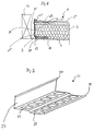
- a heat and / or sound insulation element 1 shown in FIG. 1 consists of a rigid foam insulation board 2, which is part of a thermal insulation composite system is.
- the rigid foam insulation board 2 is on the Facade of a building using a mortar 4 forming a base coat attached. On the outside there is an external plaster on the rigid foam insulation board 2 5 applied from a mortar.
- Both the base plaster 4 and the exterior plaster 5 are arranged in such a way that they extend over the rigid foam insulation board 2, that is, that the exterior plaster 5, the entire heat and / or sound insulation element 1 in the area of a large surface of the heat and / or sound insulation element 1 covers.
- the rigid foam insulation board 2 has a recess 19 on the edge rectangular cross section.
- the recess 19 extends over the entire length of the rigid foam insulation panel 2.
- a leg 20 of a profile element 21 together with a strip 22 of a non-combustible insulation material used, the leg 20 lies between the strip 22 and the rigid foam insulation board 2.
- the Strip 22 thus prevents the formation of thermal bridges across the outer surface the rigid foam insulation panel 2 extending profile element 21st
- the rigid foam insulation panel 2 is by means of a Basic plaster 4 glued to a facade 3 of a building and with one Exterior plaster 5 covered.
- the profile element 21 is U-shaped in cross section formed and thus has another in addition to the leg 20 second leg 23 and one connecting the two legs 20 and 23 Bridge 24.
- the web 24 points to increase stability 2 in the area the legs 23 and 20 arranged beads 25, the web 24 covers the entire side surface 6 of the rigid foam insulation board 2 and the strip 22 of non-combustible insulation material the area of Hard foam insulation panel 2, which covers the step formation in the area the recess 19 is not covered by the profile element 21.
- the second leg 23 has a hook element 25 at its free end and is embedded overall in the exterior plaster 5, so that the second leg 23 is anchored in the self-curing exterior plaster 5.
- the profile element 21 consists of an essentially fire-resistant Metal and can be made of aluminum, for example.
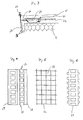
- FIG 3 an alternative embodiment of the leg 23 is connected shown with a profile element 26, as can be seen in Figure 2 is.
- the profile element 26 is L-shaped and has a first shorter leg 27 and a second longer leg 28, wherein the leg 28 with the leg 20 of the profile element 21 according to FIG 1 is functionally the same.
- the two legs 27 and 28 are substantially perpendicular to each other arranged and have bends 29 at their free ends, which in the case of the leg 27 for clamping a bracket and in the case of the leg 28 are designed as a resilient edge. It is further to recognize that the leg 28 is U-shaped in the region of its free end is angled and a perforation 34 with a plurality of rectangular Has openings.
- FIG. 4 shows a top view of the profile element 26.
- the two-part leg 23 in the embodiment according to FIG. 3 exists a first clip element 30 and a second clip element 31, which with positive and frictional, in particular spring-loaded with the first clip element 30 is connectable.
- the first clip member 30 is connectable to the bend 29 of the leg 27 of the profile element 26 and L-shaped, the second leg in the exterior plaster 5 is embedded. This second leg is U-shaped at its free end angled.
- the clip element 31 has a web, at the ends of which two legs are arranged, which essentially form a U-shaped profile.
- the one leg runs at an acute angle to the web, whereas the second opposite leg is semicircular is trained.
- the one running at an acute angle to the web Leg reaches behind the clip element 30 in the area of it the U-shaped profile, the middle section is bent, whereas the semicircular trained leg the free end of the clip member 30th overlaps. Due to the elastic properties of the material Clip elements 30 and 31 are these elements, in particular, but force also interlocked.
- a reinforcing fabric 32 Between the two clip elements 30 and 31 is a reinforcing fabric 32 with a variety of Opened openings 33, which reinforces the exterior plaster 5.
- the clip element 31 is shown in FIG. 6 and it is closed recognize that it is ladder-shaped and therefore between its webs also have openings that include the passage of the allow to be applied and liquid or tough elastic exterior plaster 5, so that an intimate bond between the reinforcing fabric 32, the clip elements 30 and 31, the rigid foam insulation board 2 and the Exterior plaster 5 can be achieved.
Landscapes
- Physics & Mathematics (AREA)
- Engineering & Computer Science (AREA)
- Architecture (AREA)
- Acoustics & Sound (AREA)
- Electromagnetism (AREA)
- Civil Engineering (AREA)
- Structural Engineering (AREA)
- Building Environments (AREA)
Applications Claiming Priority (3)
| Application Number | Priority Date | Filing Date | Title |
|---|---|---|---|
| DE19857383 | 1998-12-12 | ||
| DE1998157383 DE19857383C2 (de) | 1998-12-12 | 1998-12-12 | Wärme- und/oder Schalldämmelement |
| EP19990124164 EP1008697B1 (fr) | 1998-12-12 | 1999-12-03 | Elément d'isolation thermique et/ou phonique |
Related Parent Applications (1)
| Application Number | Title | Priority Date | Filing Date |
|---|---|---|---|
| EP19990124164 Division EP1008697B1 (fr) | 1998-12-12 | 1999-12-03 | Elément d'isolation thermique et/ou phonique |
Publications (1)
| Publication Number | Publication Date |
|---|---|
| EP1388621A1 true EP1388621A1 (fr) | 2004-02-11 |
Family
ID=30445027
Family Applications (1)
| Application Number | Title | Priority Date | Filing Date |
|---|---|---|---|
| EP03025119A Withdrawn EP1388621A1 (fr) | 1998-12-12 | 1999-12-03 | Elémemt d'isolation |
Country Status (1)
| Country | Link |
|---|---|
| EP (1) | EP1388621A1 (fr) |
Citations (5)
| Publication number | Priority date | Publication date | Assignee | Title |
|---|---|---|---|---|
| GB1299143A (en) * | 1970-03-20 | 1972-12-06 | Hunter Douglas | A clip for retaining a covering strip and a combination of the clip and covering strip |
| US5003743A (en) * | 1990-03-30 | 1991-04-02 | Vinyl Corporation | Panel support member and support arrangement |
| EP0651103A1 (fr) * | 1993-11-03 | 1995-05-03 | van Strien, Johannes Adrianus Cornelis | Isolation de mur et un système de profils en plastique pour celle-ci |
| EP0682163A2 (fr) * | 1994-05-10 | 1995-11-15 | Grünzweig + Hartmann AG | Panneau d'isolation de façade en laine minérale, notamment pour systèmes composites de parements d'isolation thermique et façades ventilées |
| DE29622383U1 (de) * | 1995-12-28 | 1997-02-20 | Neste Oy, Espoo | Verbindungsanordnung von Bauelementen |
-
1999
- 1999-12-03 EP EP03025119A patent/EP1388621A1/fr not_active Withdrawn
Patent Citations (5)
| Publication number | Priority date | Publication date | Assignee | Title |
|---|---|---|---|---|
| GB1299143A (en) * | 1970-03-20 | 1972-12-06 | Hunter Douglas | A clip for retaining a covering strip and a combination of the clip and covering strip |
| US5003743A (en) * | 1990-03-30 | 1991-04-02 | Vinyl Corporation | Panel support member and support arrangement |
| EP0651103A1 (fr) * | 1993-11-03 | 1995-05-03 | van Strien, Johannes Adrianus Cornelis | Isolation de mur et un système de profils en plastique pour celle-ci |
| EP0682163A2 (fr) * | 1994-05-10 | 1995-11-15 | Grünzweig + Hartmann AG | Panneau d'isolation de façade en laine minérale, notamment pour systèmes composites de parements d'isolation thermique et façades ventilées |
| DE29622383U1 (de) * | 1995-12-28 | 1997-02-20 | Neste Oy, Espoo | Verbindungsanordnung von Bauelementen |
Similar Documents
| Publication | Publication Date | Title |
|---|---|---|
| EP3256660B1 (fr) | Élément d'étanchéité de jointure et dispositif d'étanchéité comprenant un élément d'étanchéité de jointure de ce type | |
| EP1731685B1 (fr) | Façade isolée et ventilée pour bâtiment | |
| DE102018106183A1 (de) | Hinterlüftete Gebäudefassade sowie Verfahren zu deren Herstellung | |
| EP2746479B2 (fr) | Plaque d'isolation thermique pour un système composite d'isolation thermique, système composite d'isolation thermique | |
| EP1337725A1 (fr) | Procede pour fixer des plaques d'isolation thermique et douille necessaire a cet effet | |
| DE19860974C1 (de) | Wärme-und/oder Schalldämmelement | |
| DE202007007225U1 (de) | Bauelement für ein Wärmedämmverbundsystem | |
| DE19643618A1 (de) | Wärmedämmverbundsystem | |
| DE19951105C2 (de) | Wärme- und/oder Schalldämmelement | |
| DE202012100418U1 (de) | Gebäudefassade mit Riegelelement und Riegelelement | |
| DE19857383C2 (de) | Wärme- und/oder Schalldämmelement | |
| EP2820197B1 (fr) | Élément d'isolation | |
| EP2535473A2 (fr) | Système pare-feu ainsi que porte coupe-feu, élément mural pare-feu et panneau coupe-feu à cet effet | |
| EP0879326B1 (fr) | Panneau realise dans un materiau isolant | |
| EP1388621A1 (fr) | Elémemt d'isolation | |
| EP0982444A1 (fr) | Dispositif pour éviter l' extension du feu aux bâtiments | |
| DE10227736B4 (de) | Wärmedämmverbundsystem und Mineralfaserlamelle | |
| DE20210919U1 (de) | Gebäudewand | |
| DE4200461C2 (de) | Plattenförmiges Element, wie Tür, Fenster, Klappe | |
| EP1582645B1 (fr) | Faux plafond | |
| EP1295998B1 (fr) | Isolation acoustique et thermique; Elément d'isolation et lamelle de fibres minérales | |
| DE102018002035A1 (de) | Gebäudewand-Modul und Gebäudewand mit Gebäudewand-Modulen | |
| DE19754179C1 (de) | Schiene zum Anschließen einer Platte an eine mit einem Putz zu versehende und zur Platte senkrecht stehende Wand sowie Wandverkleidung für einen Raum mit derartiger Schiene | |
| DE102004022277A1 (de) | Vorrichtung zur Befestigung von Dämmstoffelementen an ebenen Flächen | |
| DE102013006529A1 (de) | System für den Brandschutz von Gebäuden |
Legal Events
| Date | Code | Title | Description |
|---|---|---|---|
| PUAI | Public reference made under article 153(3) epc to a published international application that has entered the european phase |
Free format text: ORIGINAL CODE: 0009012 |
|
| 17P | Request for examination filed |
Effective date: 20031119 |
|
| AC | Divisional application: reference to earlier application |
Ref document number: 1008697 Country of ref document: EP Kind code of ref document: P |
|
| AK | Designated contracting states |
Kind code of ref document: A1 Designated state(s): DE GB |
|
| AKX | Designation fees paid |
Designated state(s): DE GB |
|
| 17Q | First examination report despatched |
Effective date: 20060512 |
|
| GRAP | Despatch of communication of intention to grant a patent |
Free format text: ORIGINAL CODE: EPIDOSNIGR1 |
|
| STAA | Information on the status of an ep patent application or granted ep patent |
Free format text: STATUS: THE APPLICATION HAS BEEN WITHDRAWN |
|
| 18W | Application withdrawn |
Effective date: 20080306 |