EP1388629A1 - Charnière revenant automatiquement à sa position - Google Patents
Charnière revenant automatiquement à sa position Download PDFInfo
- Publication number
- EP1388629A1 EP1388629A1 EP02017489A EP02017489A EP1388629A1 EP 1388629 A1 EP1388629 A1 EP 1388629A1 EP 02017489 A EP02017489 A EP 02017489A EP 02017489 A EP02017489 A EP 02017489A EP 1388629 A1 EP1388629 A1 EP 1388629A1
- Authority
- EP
- European Patent Office
- Prior art keywords
- rotary hinge
- automatic homing
- spring
- gasket
- rod
- Prior art date
- Legal status (The legal status is an assumption and is not a legal conclusion. Google has not performed a legal analysis and makes no representation as to the accuracy of the status listed.)
- Withdrawn
Links
Images



Classifications
-
- E—FIXED CONSTRUCTIONS
- E05—LOCKS; KEYS; WINDOW OR DOOR FITTINGS; SAFES
- E05D—HINGES OR SUSPENSION DEVICES FOR DOORS, WINDOWS OR WINGS
- E05D11/00—Additional features or accessories of hinges
- E05D11/08—Friction devices between relatively-movable hinge parts
- E05D11/087—Friction devices between relatively-movable hinge parts with substantially axial friction, e.g. friction disks
-
- E—FIXED CONSTRUCTIONS
- E05—LOCKS; KEYS; WINDOW OR DOOR FITTINGS; SAFES
- E05F—DEVICES FOR MOVING WINGS INTO OPEN OR CLOSED POSITION; CHECKS FOR WINGS; WING FITTINGS NOT OTHERWISE PROVIDED FOR, CONCERNED WITH THE FUNCTIONING OF THE WING
- E05F1/00—Closers or openers for wings, not otherwise provided for in this subclass
- E05F1/08—Closers or openers for wings, not otherwise provided for in this subclass spring-actuated, e.g. for horizontally sliding wings
- E05F1/10—Closers or openers for wings, not otherwise provided for in this subclass spring-actuated, e.g. for horizontally sliding wings for swinging wings, e.g. counterbalance
- E05F1/12—Mechanisms in the shape of hinges or pivots, operated by springs
- E05F1/1207—Mechanisms in the shape of hinges or pivots, operated by springs with a coil spring parallel with the pivot axis
- E05F1/1215—Mechanisms in the shape of hinges or pivots, operated by springs with a coil spring parallel with the pivot axis with a canted-coil torsion spring
-
- E—FIXED CONSTRUCTIONS
- E05—LOCKS; KEYS; WINDOW OR DOOR FITTINGS; SAFES
- E05D—HINGES OR SUSPENSION DEVICES FOR DOORS, WINDOWS OR WINGS
- E05D11/00—Additional features or accessories of hinges
- E05D11/06—Devices for limiting the opening movement of hinges
-
- E—FIXED CONSTRUCTIONS
- E05—LOCKS; KEYS; WINDOW OR DOOR FITTINGS; SAFES
- E05Y—INDEXING SCHEME ASSOCIATED WITH SUBCLASSES E05D AND E05F, RELATING TO CONSTRUCTION ELEMENTS, ELECTRIC CONTROL, POWER SUPPLY, POWER SIGNAL OR TRANSMISSION, USER INTERFACES, MOUNTING OR COUPLING, DETAILS, ACCESSORIES, AUXILIARY OPERATIONS NOT OTHERWISE PROVIDED FOR, APPLICATION THEREOF
- E05Y2999/00—Subject-matter not otherwise provided for in this subclass
Definitions
- the present invention relates to an automatic homing rotary hinge, which is connected between two objects to provide rotation, positioning, and automatic homing functions for them.
- connection structures for connection, rotation, and positioning.
- the most common one is a pivot structure connected between a display and a host computer for providing the functions of adjusting and positioning angle to achieve comfortable and convenient use. Therefore, how to design a pivot structure of stable positioning, convenient use, and rigidity is a very important issue.
- a conventional pivot structure comprises a pivot 10a, an assembly board 20a, and an elastic pressing unit 30a.
- a small-diameter rod 11a of the pivot 10a is used to assemble the assembly board 20a and the elastic pressing unit 30a, and a screw nut 35a is locked thereon.
- the elastic pressing unit 30a comprises a gasket 31a, a leftward projective elastic sheet 32a, a rightward projective elastic sheet 33a, and a slab spacer 34a.
- the gasket 31a and the assembly board 20a are pivotally connected on the small-diameter rod 11a to facilitate rotation thereon.
- the leftward projective elastic sheet 32a and the rightward projective elastic sheet 33a are against each other to deform for generating elastic pressing tension and retaining resistance, thereby restricting the assembly board 20a to rotate on the small-diameter rod 11a of the pivot 10a.
- the present invention aims to provide an automatic homing rotary hinge to resolve the problems in the prior art.
- One object of the present invention is to provide an automatic homing rotary hinge, which is assembled between two objects to let them have automatic homing function.
- Another object of the present invention is to provide an automatic homing rotary hinge assembled between two objects. Static balance between the weight of one of the two object and an elastic pressing force and a friction force of the automatic homing rotary hinge is exploited to arbitrarily position the included angle between the two objects.
- Another object of the present invention is to provide a slow automatic homing rotary hinge having the same effect as an oil press so as to avoid impact between two objects assembled on the automatic homing rotary hinge due to the weight of one of the two objects and thus overcome the drawback of easy destruction of the two objects when they are closed.
- Another object of the present invention is to provide an automatic homing rotary hinge. Static balance between the weight of one object and the automatic homing rotary hinge is exploited to achieve positioning effect between two objects. The lifetime of use of a push gasket thereof can thus be lengthened.
- an automatic homing rotary hinge which comprises a pivotal rod, a spring assembled on the pivotal rod, an assembly board, and a friction portion.
- the pivotal rod and the assembly board are locked between two objects to adjust the included angle between them.
- the friction portion comprises a spacer, a baffle, a push gasket, and a skidproof gasket, which are assembled on a small-diameter rod in order.
- a screw nut is locked onto the small-diameter rod.
- Degree of deformation of the push gasket abutting against the baffle is adjusted to generate different elastic pressing forces and friction forces, thereby changing the magnitude of friction force between the spacer, a guide plate of the assembly board, and the baffle to provide a torsion for stopping relative motion between the pivotal rod and the assembly board.
- Static balance between the spring, the weight of one of the two objects, and action forces of the friction portion is exploited to arbitrarily position the included angle between the two objects.
- the spring is used to restore the original included angle between the two objects.
- an automatic homing rotary hinge of the present invention comprises a pivotal rod 10, a spring 20 slipped onto the pivotal rod 10, an assembly board 30, and a friction portion 40.
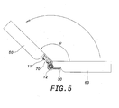
- the pivotal rod 10 and the assembly board 30 are locked onto a first object 50 and a second object 60 (shown in Fig. 5), and are used to adjust the included angle between the two objects 50 and 60.
- a slab 11 projects from the front end face of the pivotal rod 10, and a small-diameter rod 12 projects from the rear end face of the pivotal rod 10.
- Planes 13 are formed at upper and lower sides of the pivotal rod 10.
- the spring 20 can be a torsion spring, and has a first arm 21 and a second arm 22.
- One side of the assembly board 30 is bent to form a guide plate 31.
- a pivotal hole 32 and a locking portion 33 are formed on the guide plate 31.
- the small-diameter rod 12 passes through the pivotal hole 32 to assemble the assembly board 30 onto the small-diameter rod 12.
- the assembly board 30 is assembled behind the spring 20.
- a first circular hole 34 is formed on the assembly board 30 so that the second object 60 can be locked onto the assembly board 30, as shown in Fig. 5.
- the friction portion 40 comprises a spacer 41, a baffle 42, a push gasket 43, and a skidproof gasket 44, each of which has a through hole 45.
- the through holes 45 of the spacer 41, the baffle 42, the push gasket 43, and the skidproof gasket 44 correspond to the cross section of the small-diameter rod 12.
- the spacer 41, the baffle 42, the push gasket 43, and the skidproof gasket 44 are slipped onto the small-diameter rod 12 in order, and are assembled behind the assembly board 30. Finally, a screw nut 49 is locked onto the small-diameter rod 12.
- Another spacer 41 is assembled between the spring 20 and the assembly board 30.
- Elasticity of the screw nut 49 locked onto the small-diameter rod 12 can be adjusted to force the push gasket 43 to abut against the baffle 42.
- Deformation of the push gasket 43 generates an elastic pressing force and a friction force to adjust the magnitude of the friction force between the spacer 41, the guide plate 31 of the assembly board 30, and the baffle 42, thereby providing a torsion for stopping relative motion between the pivotal rod 10 and the assembly board 30.
- a projective portion 46 is disposed on the baffle 42, and is locked onto the locking portion 33 of the guide plate 31 to limit the rotation angle of the assembly board 30 on the small-diameter rod 12.
- the slab 11 of the pivotal rod 10 has a first screw hole 14 locked with a fixing sheet 70.
- the fixing sheet 70 has a second circular hole 71 locked with the second object 60 (shown in Fig. 5).
- the first arm 21 and the second arm 22 of the spring 20 slipped onto the pivotal rod 10 abut against the side face of the assembly board 30 and the upper end face of the fixing sheet 70, respectively.
- a torsion is applied onto the spring 20 beforehand to let it have a restoring force.
- the direction of the weight of the first object 50 is opposite to that of the torsion of the spring 20 (shown in Fig.
- the slab 11 of the pivotal rod 10 touches the first object 50 (shown in Fig. 6), and the second arm 22 of the spring 20 abuts against the slab 11 of the pivotal rod 10 (not shown).
- the automatic homing rotary hinge of the present invention can generate automatic homing effect.
- the included angle between the two objects can be arbitrarily positioned within a certain range.
- the lifetime of use of the skidproof gasket can also be lengthened.
- the two objects are closed more slowly to avoid impact between them and thus overcome the drawback of easy destruction of the two objects.
Landscapes
- Engineering & Computer Science (AREA)
- Mechanical Engineering (AREA)
- Pivots And Pivotal Connections (AREA)
- Closing And Opening Devices For Wings, And Checks For Wings (AREA)
Priority Applications (2)
| Application Number | Priority Date | Filing Date | Title |
|---|---|---|---|
| EP02017489A EP1388629A1 (fr) | 2002-08-05 | 2002-08-05 | Charnière revenant automatiquement à sa position |
| US10/212,270 US20040025298A1 (en) | 2002-08-05 | 2002-08-06 | Elevation angle adjustment mechanism of display |
Applications Claiming Priority (2)
| Application Number | Priority Date | Filing Date | Title |
|---|---|---|---|
| EP02017489A EP1388629A1 (fr) | 2002-08-05 | 2002-08-05 | Charnière revenant automatiquement à sa position |
| US10/212,270 US20040025298A1 (en) | 2002-08-05 | 2002-08-06 | Elevation angle adjustment mechanism of display |
Publications (1)
| Publication Number | Publication Date |
|---|---|
| EP1388629A1 true EP1388629A1 (fr) | 2004-02-11 |
Family
ID=32395431
Family Applications (1)
| Application Number | Title | Priority Date | Filing Date |
|---|---|---|---|
| EP02017489A Withdrawn EP1388629A1 (fr) | 2002-08-05 | 2002-08-05 | Charnière revenant automatiquement à sa position |
Country Status (2)
| Country | Link |
|---|---|
| US (1) | US20040025298A1 (fr) |
| EP (1) | EP1388629A1 (fr) |
Families Citing this family (14)
| Publication number | Priority date | Publication date | Assignee | Title |
|---|---|---|---|---|
| JP4141249B2 (ja) * | 2002-12-25 | 2008-08-27 | ノキア コーポレイション | 一時角度設定機能付ヒンジ装置 |
| CN2736889Y (zh) * | 2004-07-17 | 2005-10-26 | 鸿富锦精密工业(深圳)有限公司 | 便携式光盘播放器 |
| US7275286B2 (en) * | 2005-07-13 | 2007-10-02 | Shin Zu Shing Co., Ltd. | Pivot device |
| TWI308997B (en) * | 2005-11-25 | 2009-04-21 | Hon Hai Prec Ind Co Ltd | Hinge mechanism |
| CN100467891C (zh) * | 2005-12-01 | 2009-03-11 | 鸿富锦精密工业(深圳)有限公司 | 铰链装置 |
| CN100467890C (zh) * | 2005-12-01 | 2009-03-11 | 鸿富锦精密工业(深圳)有限公司 | 铰链结构 |
| US20080120811A1 (en) * | 2006-11-28 | 2008-05-29 | Ting-Hsien Wang | Adjustable hinge |
| TW200920957A (en) * | 2007-11-02 | 2009-05-16 | Jarllytec Co Ltd | Cover-type rotation joint device capable of easily calibrating spindle |
| US7861377B2 (en) * | 2007-12-13 | 2011-01-04 | Shin Zu Shing Co., Ltd. | Abrasion-enhanced hinge |
| US20090165252A1 (en) * | 2007-12-31 | 2009-07-02 | Jr-Jiun Chern | Hinge Assembly |
| US20090172916A1 (en) * | 2008-01-04 | 2009-07-09 | Jr-Jiun Chern | Hinge Assembly |
| TW201015268A (en) * | 2008-10-06 | 2010-04-16 | Asustek Comp Inc | Portable electronic device and hinge module thereof |
| CN101825138A (zh) * | 2009-03-07 | 2010-09-08 | 鸿富锦精密工业(深圳)有限公司 | 铰链结构及采用该铰链结构的电子装置 |
| JP6208916B2 (ja) * | 2015-09-24 | 2017-10-04 | スガツネ工業株式会社 | ヒンジ |
Citations (3)
| Publication number | Priority date | Publication date | Assignee | Title |
|---|---|---|---|---|
| US5208944A (en) * | 1992-06-16 | 1993-05-11 | Lu Sheng N | Hinge device for casings |
| US5894633A (en) * | 1996-01-18 | 1999-04-20 | Katoh Electrical Machinery Co., Ltd. | Tilt hinge |
| US5970819A (en) * | 1997-04-21 | 1999-10-26 | Katoh Electrical Machinery Co., Ltd. | Operating device of opening-closing body |
Family Cites Families (6)
| Publication number | Priority date | Publication date | Assignee | Title |
|---|---|---|---|---|
| US6108868A (en) * | 1998-03-30 | 2000-08-29 | Lin; Davys | Positioning hinge having a cam block |
| KR100390410B1 (ko) * | 2000-06-20 | 2003-07-07 | 엘지전자 주식회사 | 힌지 조립체 |
| US20020083554A1 (en) * | 2001-01-03 | 2002-07-04 | Lu Sheng-Nan | Concealed retaining device for a pivot |
| US6481057B2 (en) * | 2001-03-20 | 2002-11-19 | Wen-Chi Lin | Positioning hinge adapted between a computer main body and a display |
| US6430777B1 (en) * | 2001-04-04 | 2002-08-13 | Lu Sheng-Nan | Pivot device for a notebook computer |
| KR100414670B1 (ko) * | 2001-11-28 | 2004-01-13 | 삼성전자주식회사 | 힌지장치 |
-
2002
- 2002-08-05 EP EP02017489A patent/EP1388629A1/fr not_active Withdrawn
- 2002-08-06 US US10/212,270 patent/US20040025298A1/en not_active Abandoned
Patent Citations (3)
| Publication number | Priority date | Publication date | Assignee | Title |
|---|---|---|---|---|
| US5208944A (en) * | 1992-06-16 | 1993-05-11 | Lu Sheng N | Hinge device for casings |
| US5894633A (en) * | 1996-01-18 | 1999-04-20 | Katoh Electrical Machinery Co., Ltd. | Tilt hinge |
| US5970819A (en) * | 1997-04-21 | 1999-10-26 | Katoh Electrical Machinery Co., Ltd. | Operating device of opening-closing body |
Also Published As
| Publication number | Publication date |
|---|---|
| US20040025298A1 (en) | 2004-02-12 |
Similar Documents
| Publication | Publication Date | Title |
|---|---|---|
| EP1388629A1 (fr) | Charnière revenant automatiquement à sa position | |
| US6587333B2 (en) | Flat panel display apparatus and tilt/swivel mechanism therein | |
| US5632066A (en) | Pivot hinge for portable computers | |
| KR100703160B1 (ko) | 디스플레이장치 | |
| US6108868A (en) | Positioning hinge having a cam block | |
| US5970819A (en) | Operating device of opening-closing body | |
| CN201246405Y (zh) | 枢纽器及其干涉组件 | |
| US20140063750A1 (en) | Hinge, supporting module having the hinge, and display device having the supporting module | |
| US20030227739A1 (en) | Tilting and shielding apparatus of monitor | |
| US7150440B2 (en) | Adjustable support frame for a display screen | |
| US20030042385A1 (en) | Liquid crystal display with a ball-and-socket mounting joint | |
| US6694569B2 (en) | Hinge device | |
| CN101223366A (zh) | 弹簧加载的夹紧机构 | |
| CN101614238A (zh) | 铰链结构 | |
| US6525929B2 (en) | Computer chassis door with position damping detent hinge | |
| JP2003348495A (ja) | モニタ | |
| TWI704444B (zh) | 觸控板結構 | |
| US20220179459A1 (en) | Pivot Device with Multi-Stage Switching | |
| US20110102982A1 (en) | Electronic apparatus | |
| US6388872B1 (en) | Portable computer with cover and torsion member | |
| US8084689B2 (en) | Hinge assembly and electronic device using the same | |
| US20070064382A1 (en) | Auxiliary fixing mechanism for an interface card | |
| US20040032578A1 (en) | Hinge device for copier lid | |
| CN201475155U (zh) | 枢纽器 | |
| JP2602161Y2 (ja) | チルトヒンジ |
Legal Events
| Date | Code | Title | Description |
|---|---|---|---|
| PUAI | Public reference made under article 153(3) epc to a published international application that has entered the european phase |
Free format text: ORIGINAL CODE: 0009012 |
|
| AK | Designated contracting states |
Kind code of ref document: A1 Designated state(s): AT BE BG CH CY CZ DE DK EE ES FI FR GB GR IE IT LI LU MC NL PT SE SK TR |
|
| AX | Request for extension of the european patent |
Extension state: AL LT LV MK RO SI |
|
| STAA | Information on the status of an ep patent application or granted ep patent |
Free format text: STATUS: THE APPLICATION HAS BEEN WITHDRAWN |
|
| 18W | Application withdrawn |
Effective date: 20040616 |