EP1388657B1 - Ensemble de vanne - Google Patents
Ensemble de vanne Download PDFInfo
- Publication number
- EP1388657B1 EP1388657B1 EP20030015738 EP03015738A EP1388657B1 EP 1388657 B1 EP1388657 B1 EP 1388657B1 EP 20030015738 EP20030015738 EP 20030015738 EP 03015738 A EP03015738 A EP 03015738A EP 1388657 B1 EP1388657 B1 EP 1388657B1
- Authority
- EP
- European Patent Office
- Prior art keywords
- compensation element
- offset compensation
- valve assembly
- actuator
- offset
- Prior art date
- Legal status (The legal status is an assumption and is not a legal conclusion. Google has not performed a legal analysis and makes no representation as to the accuracy of the status listed.)
- Expired - Lifetime
Links
- 238000005452 bending Methods 0.000 claims description 11
- 230000005540 biological transmission Effects 0.000 claims description 8
- 238000002485 combustion reaction Methods 0.000 claims description 5
- 238000004519 manufacturing process Methods 0.000 description 4
- 238000009434 installation Methods 0.000 description 2
- 238000005266 casting Methods 0.000 description 1
- 230000000295 complement effect Effects 0.000 description 1
- 230000008878 coupling Effects 0.000 description 1
- 238000010168 coupling process Methods 0.000 description 1
- 238000005859 coupling reaction Methods 0.000 description 1
- 238000004512 die casting Methods 0.000 description 1
- 238000003780 insertion Methods 0.000 description 1
- 230000037431 insertion Effects 0.000 description 1
- 238000003754 machining Methods 0.000 description 1
- 239000000463 material Substances 0.000 description 1
- 238000003825 pressing Methods 0.000 description 1
- 238000007528 sand casting Methods 0.000 description 1
- 238000003860 storage Methods 0.000 description 1
Images


Classifications
-
- F—MECHANICAL ENGINEERING; LIGHTING; HEATING; WEAPONS; BLASTING
- F02—COMBUSTION ENGINES; HOT-GAS OR COMBUSTION-PRODUCT ENGINE PLANTS
- F02D—CONTROLLING COMBUSTION ENGINES
- F02D9/00—Controlling engines by throttling air or fuel-and-air induction conduits or exhaust conduits
- F02D9/08—Throttle valves specially adapted therefor; Arrangements of such valves in conduits
- F02D9/10—Throttle valves specially adapted therefor; Arrangements of such valves in conduits having pivotally-mounted flaps
- F02D9/109—Throttle valves specially adapted therefor; Arrangements of such valves in conduits having pivotally-mounted flaps having two or more flaps
- F02D9/1095—Rotating on a common axis, e.g. having a common shaft
Definitions
- the invention relates to a flap arrangement for motor vehicle internal combustion engines.
- the flap assembly is suitable for V-engines.
- Switching flaps serve to vary the length of intake ducts.
- On off DE 196 14 474 known air intake duct system has a spiral-shaped air intake duct for each cylinder.
- the intake of air via a central, arranged within the spiral intake ducts collecting inlet channel takes place. Air is sucked in through the collective inlet channel provided jointly for all air intake ducts and directed to the internal combustion engine via the individual air intake ducts.
- a short-circuit channel is provided. This short-circuit channel, which can be opened and closed with a switching flap, is connected to the collecting inlet channel and in each case to an air intake channel.
- Several switching flaps are possibly connected to each other via a common shaft.
- the bearing of the shaft takes place in a channel element, such as a housing part of the air intake duct system.
- a channel element such as a housing part of the air intake duct system.
- the air intake duct system for example, two housing halves, wherein the shift shaft is inserted between the housing halves.
- the actuation of the common switching shaft is also via an electric motor or the like., Which in turn is connected directly or via a lever mechanism with the switching shaft.
- the object of the invention is to provide a flap assembly can be compensated in the manufacturing tolerances in a simple manner and in particular with a small footprint.
- the flap assembly according to the invention for motor vehicle internal combustion engines has at least one flap which is connected to a switching shaft.
- a plurality of flaps are connected to a common control shaft.
- the switching shaft is connected to an actuating device, such as an electric motor or the like., Wherein the connection via an intermediate gear or suitable drive lever, can take place.
- an actuating device such as an electric motor or the like.
- a rod-shaped offset compensation element is provided in the rod-shaped offset compensation element is an intermediate element between the shift shaft and the actuator or a drive lever or the like. the actuator.
- the rod-shaped offset compensation element according to the invention has the significant advantage that the space requirement is considerably lower. Furthermore, the assembly of a single rod-shaped Elements that can be inserted, for example in corresponding receptacles on the shift shaft and / or the actuator considerably easier.
- the offset compensation element with the pivot shaft and / or the actuator via a receptacle which is provided on the pivot shaft or the actuator, connectable.
- the receptacle is preferably a plug-in connection, wherein a receptacle is preferably provided in each case on the pivot shaft and / or the actuating device.
- the rod-shaped offset compensation element has for connecting preferably a head-like extension, which can be inserted into a recess serving as a receptacle.
- the offset compensation element can be designed to be elastic.
- the head-like extension of the offset compensation element made of suitable elastically deformable plastic or the like. be prepared and / or have the offset compensation element in this area, for example, slots.
- the connection can also be reversed, so that, for example, the shift shaft has a head-like or spherical approach, which is encompassed by a neck of the offset compensation element.
- the rod-shaped offset compensation element according to the invention is preferably tiltable about an axis perpendicular to the longitudinal axis of the pivot shaft to compensate for the offset substantially.
- an offset between the longitudinal axis of the pivot shaft and the actuating device or a drive lever or the like. be bridged or compensated for the actuator.
- connection between the offset compensation element and the pivot axis or the actuator is realized via a connecting element which is torsionally rigid, but bendable.
- the connecting element for example in one piece with the switching shaft or integrally connected to the actuating device.
- the connecting element is made of plastic, for example, the connection between the rod-shaped offset compensation element and, for example, the drive lever via a plastic strap or plastic web can be done. Since the offset compensation element in this embodiment torsionally rigid and extremely flexible with the actuator or a component of the actuator or the pivot shaft is connected, the assembly is simplified because only one connection must be mounted. In this connection, it is then preferably the connection described above between a recording and an example, head-like extension of the offset compensation element, so that the offset compensation element only has to be inserted into the receptacle.
- the rod-shaped offset compensation element itself is bendable about a substantially perpendicular to its longitudinal axis extending bending axis and formed substantially torsionally rigid.
- the offset caused by manufacturing tolerances can thus be compensated by a slight bending of the offset compensation element.
- Even with such a Offset compensation element assembly is considerably simplified compared to the installation of a coupling. Furthermore, the space required is smaller.
- the offset compensation element itself is bendable about the bending axis, it is possible to arrange the connecting pieces or connecting elements between the switching shaft and the offset compensation element or between the actuating device and the offset compensation element displaced parallel to one another. This has the consequence that a tiltability of the fittings in a receptacle of the shaft or the actuator is not required.
- the fittings can thus be designed simpler. For example, a simple latching connection or the like. sufficient.
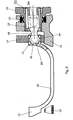
- a flap arrangement ( Fig. 1 ) has a flap 10, for example, a shaft, swirl or Tumbleklappe on.
- the flap 10 is connected to a switching shaft 12.
- the switching shaft 12 is integrally connected as an approach with the flap 10, wherein a plurality of flaps 10 are connected to each other via the common control shaft 12.
- the switching shaft 12 is mounted in bearing parts 14 and arranged in a housing 16. With the switching shaft 12, the rod-shaped offset compensation element 18 according to the invention is connected.
- the offset compensation element 18 is further connected to a mounted in the housing 16 drive lever 20 which is part of an actuator.
- the actuating device further comprises an electric servomotor or the like. Between a cylindrical projection 22 of the drive lever 20 and the housing 16, a circumferential seal 24 is provided.
- the rod-shaped offset compensation element 18 has a head or an extension 26 at each end in the illustrated embodiment.
- the connected to the shaft 12 head 26 is disposed within a recess 28 formed in the illustrated embodiment receptacle 28.
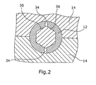
- the head 26 is formed in the illustrated embodiment as a hexagon and thus has six rotation transmission surfaces 30 (FIG. Fig. 2 ) on.
- the rotation transmission surfaces 30, of which 4,6,8,10,12 etc. may be provided, for example, allow a transmission of a rotational movement of the offset compensation element 18 about the longitudinal axis 32.
- the receptacle 28 also has a regular hexagonal cross-section ( Fig. 2 ).
- the shift shaft 12 slots 34, so that the shift shaft 12 elastically expanded in this area by pressing the head 26 and returns to fully inserted head 26 in the starting position.
- the two heads 26 of the offset compensation element 18 in the receptacle 28 of the shaft 12 and in a receptacle 40 of the drive lever 20 respectively Direction of an arrow 42 or 44 pivotally.
- the rotation transmission surfaces 30 are curved in the longitudinal direction of the offset compensation element 18 ( Fig. 1 ).
- the receptacle 28 in the shaft 12 has complementary curved surfaces to the six rotation transfer surfaces.
- the offset compensation element 18 is thus pivotable about a perpendicular to the longitudinal axis 46 of the offset compensation element 18 extending axis 48 and 50, respectively.
- the receptacle 40 in the drive lever 20 and the head 26 of the offset compensation element, which is held in the receptacle 40, are corresponding to the opposite head 26, which is arranged on the receptacle 40 of the shaft is formed.
- the receptacle 40 is also slotted to allow elastic expansion.
- the projection 22 of the drive lever 20, which serves to support the drive lever 20 in the housing 16, formed as a hollow cylinder, so that in particular more than half the length of the offset compensation element is disposed within the drive lever 20.
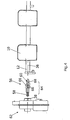
- the second preferred embodiment differs from the first embodiment ( FIGS. 1 and 2 ) only by the connection between the drive lever 20 and the offset compensation element 18. Identical and similar components of the embodiment are thus identified by the same reference numerals.
- the offset compensation element 18 is connected directly to the drive lever 20 in the illustrated embodiment.
- a connecting element 52 which may be formed like a film, is provided instead of the head 26, .
- the connecting element is torsionally rigid, so that a rotation or pivoting of the drive lever 20 is transmitted to the shaft 12.
- the connecting element 52 which is preferably made of plastic, however, is bendable, so that pivoting in the direction of an arrow 54 is possible. In this way, an offset of the shaft 12 and the drive lever 20 can be compensated. Of course, a compensation of the offset perpendicular to the plane is possible.
- the connecting element whose thickness depends on the material used to allow a corresponding bendability, for example, may be slotted or formed as a continuous circumferential ring. In order to allow a suitable bendability, the offset compensation element 18 is hollow in the region of the connecting element 52.
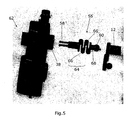
- the offset compensation element 56 is formed such that the two connecting pieces 58,60, which are suitable for connection to an actuating device 62 and / or 56, are not offset by a rod-shaped offset compensation element 18 arranged at an angle. serve the shaft 12, are displaceable parallel to each other, wherein an intermediate piece 64 of the offset compensation element 56 is bent.
- the head-shaped connecting piece 60 in FIG Fig. 4 parallel upwards pushed while the position of the connector 58 remains unchanged.
- the intermediate piece 64 has bending regions 66.
- the intermediate piece 64 is partially meandering.
- the offset compensation element 56 is thus bendable about a perpendicular to its longitudinal axis 68 extending bending axis.
- the connector 60 corresponds in the embodiment of the head 26 of the offset compensation element 18 ( Fig. 1 ). As a result, an additional pivoting of the offset compensation element 56 relative to the shaft 12 and thus a further simplified compensation of the offset is possible.
- the connector 58 is configured as a conventional latching or snap connection, but may also be configured according to the head 60.
Landscapes
- Engineering & Computer Science (AREA)
- Chemical & Material Sciences (AREA)
- Combustion & Propulsion (AREA)
- Mechanical Engineering (AREA)
- General Engineering & Computer Science (AREA)
- Control Of Throttle Valves Provided In The Intake System Or In The Exhaust System (AREA)
- Gear-Shifting Mechanisms (AREA)
- Transmission Devices (AREA)
- Pivots And Pivotal Connections (AREA)
Claims (12)
- Ensemble de vanne pour moteurs à combustion interne de véhicules motorisés, comprenant:au moins une vanne (10),un arbre de changement (12) relié à ladite vanne (10),un actionneur (20, 62) connecté avec l'arbre de changement (12), etun élément compensateur de décalage (18, 56) prévu entre l'arbre de changement (12) et l'actionneur (20, 62),l'élément compensateur de décalage (18, 56) étant en forme de bâton,
caractérisé en ce quel'arbre de changement (12) ou l'actionneur (20, 62) comprend un logement (28, 40) pour le raccordement avec l'élément compensateur de décalage (18, 56), ledit élément compensateur de décalage (18, 56) étant apte à être basculé par rapport au logement (28, 40). - Ensemble de vannes selon la revendication 1, caractérisé en ce que le logement (28, 40) et l'élément compensateur de décalage (18, 56) sont aptes à être imbriqué l'un dans l'autre.
- Ensemble de vannes selon la revendication 1 ou 2, caractérisé en ce que le logement (28, 40) et/ou une saillie de l'élément compensateur de décalage (18, 56) est déformable élastiquement, particulièrement élastiquement expansible ou élastiquement compressible.
- Ensemble selon l'une quelconque des revendications 1 à 3, caractérisé en ce que l'élément compensateur de décalage (18, 56) peut être basculé autour d'un axe (48, 50) s'étendent sensiblement perpendiculairement à l'axe longitudinal (36) de l'arbre de changement (12).
- Ensemble selon l'une quelconque des revendications 1 à 4, caractérisé en ce que l'élément compensateur de décalage comprend des faces de transmission de rotation (30) pour la transmission d'un mouvement rotatif depuis l'actionneur (20, 62) à l'arbre de changement (12).
- Ensemble selon la revendication 5, caractérisé en ce que les faces de transmission de rotation (30) sont courbées sensiblement vers l'axe longitudinal (36) de l'élément compensateur de décalage (18).
- Ensemble selon l'une quelconque des revendications 1 à 6, caractérisé en ce que l'élément compensateur de décalage (18) est raccordé à l'arbre de changement (12) et/ou à l'actionneur (20) par un élément de raccord (53) rigide à la torsion et flexible.
- Ensemble selon l'une quelconque des revendications 1 à 7, caractérisé en ce que l'élément compensateur de décalage (56) est réalisé de sorte qu'il est flexible et rigide à la torsion autour d'un axe de flexion s'étendant sensiblement perpendiculairement par rapport à un axe longitudinal (68).
- Ensemble selon l'une quelconque des revendications 1 à 8, caractérisé en ce que, pour son flexion, l'élément compensateur de décalage (56) comprend au moins une zone de flexion (66).
- Ensemble selon la revendication 8 ou 9, caractérisé en ce que l'élément compensateur de décalage (56) comprend au moins deux zones de flexion (66) dont les axes de flexion sont disposés, de préférence, sous un angle de 90° l'un par rapport à l'autre.
- Ensemble selon l'une quelconque des revendications 1 à 10, caractérisé en ce que l'élément compensateur de décalage (56) comprend deux pièces de raccord (58, 60) pour le raccordement à l'arbre de changement (12) et à l'actionneur (62), respectivement, les pièces étant déplaçables en parallèle l'un par rapport à l'autre par flexion de l'élément compensateur de décalage (56).
- Ensemble selon l'une quelconque des revendications 8 à 11, caractérisé en ce que l'élément compensateur de décalage (56) est réalisé au moins partiellement en forme de méandre.
Applications Claiming Priority (2)
| Application Number | Priority Date | Filing Date | Title |
|---|---|---|---|
| DE10236587 | 2002-08-09 | ||
| DE2002136587 DE10236587A1 (de) | 2002-08-09 | 2002-08-09 | Klappenanordnung |
Publications (3)
| Publication Number | Publication Date |
|---|---|
| EP1388657A2 EP1388657A2 (fr) | 2004-02-11 |
| EP1388657A3 EP1388657A3 (fr) | 2007-03-14 |
| EP1388657B1 true EP1388657B1 (fr) | 2010-02-10 |
Family
ID=30128796
Family Applications (1)
| Application Number | Title | Priority Date | Filing Date |
|---|---|---|---|
| EP20030015738 Expired - Lifetime EP1388657B1 (fr) | 2002-08-09 | 2003-07-10 | Ensemble de vanne |
Country Status (2)
| Country | Link |
|---|---|
| EP (1) | EP1388657B1 (fr) |
| DE (2) | DE10236587A1 (fr) |
Families Citing this family (3)
| Publication number | Priority date | Publication date | Assignee | Title |
|---|---|---|---|---|
| DE102004009502B3 (de) * | 2004-02-27 | 2005-11-03 | Siemens Ag | Klappensystem, insbesondere zur Änderung der Strömungsverhältnisse an Einlassventilen |
| DE102005029798B4 (de) * | 2005-06-27 | 2015-02-05 | Volkswagen Ag | Schaltbauteil für ein Saugrohr einer Brennkraftmaschine |
| DE102007005686B4 (de) | 2007-02-05 | 2009-01-02 | Siemens Ag | Saugrohranlage für eine Brennkraftmaschine |
Family Cites Families (5)
| Publication number | Priority date | Publication date | Assignee | Title |
|---|---|---|---|---|
| FR2108817B1 (fr) * | 1970-10-08 | 1977-01-21 | Citroen Sa | |
| JPS5925048A (ja) * | 1982-08-02 | 1984-02-08 | Yamaha Motor Co Ltd | 多気筒エンジンの空気弁作動装置 |
| US4566424A (en) * | 1984-07-30 | 1986-01-28 | Outboard Marine Corporation | Flexible coupling for carburetors |
| DE19614474B4 (de) * | 1996-04-12 | 2005-08-04 | Pierburg Gmbh | Luftansaugkanalsystem für Brennkraftmaschinen |
| DE19918777A1 (de) * | 1999-04-24 | 2000-10-26 | Mann & Hummel Filter | Schaltklappenverband aus montagegespritzten Schaltklappen oder Klappenmodulen |
-
2002
- 2002-08-09 DE DE2002136587 patent/DE10236587A1/de not_active Ceased
-
2003
- 2003-07-10 EP EP20030015738 patent/EP1388657B1/fr not_active Expired - Lifetime
- 2003-07-10 DE DE50312403T patent/DE50312403D1/de not_active Expired - Lifetime
Also Published As
| Publication number | Publication date |
|---|---|
| DE50312403D1 (de) | 2010-03-25 |
| EP1388657A2 (fr) | 2004-02-11 |
| DE10236587A1 (de) | 2004-02-26 |
| EP1388657A3 (fr) | 2007-03-14 |
Similar Documents
| Publication | Publication Date | Title |
|---|---|---|
| DE60100267T2 (de) | Elektronische Drosselklappensteuervorrichtung mit Aufrechterhaltung von Zahnradkamm und Zahnradausrichtung | |
| EP1175556B1 (fr) | Ensemble volets de commande constitue de volets de commande, moules par injection au moment du montage, ou de modules a volets | |
| EP2458182B1 (fr) | Dispositif destiné à influencer des débits volumiques de gaz, procédé de commande et/ou de réglage d'un flux de gaz ou d'un flux d'air de suralimentation, système d'échappement et véhicule automobile | |
| EP0362566B1 (fr) | Support élastique | |
| EP0726388A1 (fr) | Dispositif d'admission | |
| DE102018103961A1 (de) | Variabler Ventiltrieb eines Verbrennungskolbenmotors | |
| EP1926907B1 (fr) | Dispositif destine a commander un flux de gaz d'echappement | |
| WO2014063697A1 (fr) | Cliquet d'entraînement pour embrayage à friction à rattrapage d'usure | |
| DE102017222465B4 (de) | Klappeneinrichtung für den Abgasstrang eines Verbrennungsmotors | |
| DE102016123738B4 (de) | Klappenvorrichtung | |
| EP1950441A2 (fr) | Embrayage à friction avec dispositif de rattrapage automatique | |
| DE10126063B4 (de) | Klappenvorrichtung | |
| EP1101021B1 (fr) | Systeme de canaux, en particulier collecteur d'admission d'un moteur a combustion interne | |
| EP1505281B1 (fr) | Module d'admission | |
| EP1388652B1 (fr) | Système de conduit d'admission | |
| EP1388657A2 (fr) | Ensemble de vanne | |
| EP1808612B1 (fr) | Butée de débrayage d'un véhicule automobile | |
| EP1291504B1 (fr) | Dispositif de volets de commande | |
| DE3418772C1 (de) | Mechanisch betätigte Reibungskupplung, insbesondere für Kraftfahrzeuge | |
| EP2233729A1 (fr) | Dispositif de clapets pour un moteur à combustion interne | |
| DE10330225B4 (de) | Klappenvorrichtung für eine Verbrennungskraftmaschine | |
| DE19530582C2 (de) | Schließklappe für einen Strömungskanal | |
| DE102009043627A1 (de) | Ansaugeinrichtung für Verbrennungsmotoren | |
| DE3726548C2 (fr) | ||
| EP1563174B1 (fr) | Procede pour produire un boitier de papillon |
Legal Events
| Date | Code | Title | Description |
|---|---|---|---|
| PUAI | Public reference made under article 153(3) epc to a published international application that has entered the european phase |
Free format text: ORIGINAL CODE: 0009012 |
|
| AK | Designated contracting states |
Kind code of ref document: A2 Designated state(s): AT BE BG CH CY CZ DE DK EE ES FI FR GB GR HU IE IT LI LU MC NL PT RO SE SI SK TR |
|
| AX | Request for extension of the european patent |
Extension state: AL LT LV MK |
|
| PUAL | Search report despatched |
Free format text: ORIGINAL CODE: 0009013 |
|
| RIC1 | Information provided on ipc code assigned before grant |
Ipc: F02D 9/10 20060101ALI20070201BHEP Ipc: F02D 9/08 20060101AFI20031028BHEP |
|
| AK | Designated contracting states |
Kind code of ref document: A3 Designated state(s): AT BE BG CH CY CZ DE DK EE ES FI FR GB GR HU IE IT LI LU MC NL PT RO SE SI SK TR |
|
| AX | Request for extension of the european patent |
Extension state: AL LT LV MK |
|
| 17P | Request for examination filed |
Effective date: 20070628 |
|
| 17Q | First examination report despatched |
Effective date: 20070821 |
|
| AKX | Designation fees paid |
Designated state(s): DE FR GB IT |
|
| GRAP | Despatch of communication of intention to grant a patent |
Free format text: ORIGINAL CODE: EPIDOSNIGR1 |
|
| GRAS | Grant fee paid |
Free format text: ORIGINAL CODE: EPIDOSNIGR3 |
|
| GRAA | (expected) grant |
Free format text: ORIGINAL CODE: 0009210 |
|
| AK | Designated contracting states |
Kind code of ref document: B1 Designated state(s): DE FR GB IT |
|
| REG | Reference to a national code |
Ref country code: GB Ref legal event code: FG4D Free format text: NOT ENGLISH |
|
| REF | Corresponds to: |
Ref document number: 50312403 Country of ref document: DE Date of ref document: 20100325 Kind code of ref document: P |
|
| PGFP | Annual fee paid to national office [announced via postgrant information from national office to epo] |
Ref country code: FR Payment date: 20100802 Year of fee payment: 8 Ref country code: IT Payment date: 20100729 Year of fee payment: 8 |
|
| PLBE | No opposition filed within time limit |
Free format text: ORIGINAL CODE: 0009261 |
|
| STAA | Information on the status of an ep patent application or granted ep patent |
Free format text: STATUS: NO OPPOSITION FILED WITHIN TIME LIMIT |
|
| PGFP | Annual fee paid to national office [announced via postgrant information from national office to epo] |
Ref country code: GB Payment date: 20100726 Year of fee payment: 8 |
|
| 26N | No opposition filed |
Effective date: 20101111 |
|
| PGFP | Annual fee paid to national office [announced via postgrant information from national office to epo] |
Ref country code: DE Payment date: 20110926 Year of fee payment: 9 |
|
| GBPC | Gb: european patent ceased through non-payment of renewal fee |
Effective date: 20110710 |
|
| REG | Reference to a national code |
Ref country code: FR Ref legal event code: ST Effective date: 20120330 |
|
| PG25 | Lapsed in a contracting state [announced via postgrant information from national office to epo] |
Ref country code: FR Free format text: LAPSE BECAUSE OF NON-PAYMENT OF DUE FEES Effective date: 20110801 |
|
| PG25 | Lapsed in a contracting state [announced via postgrant information from national office to epo] |
Ref country code: IT Free format text: LAPSE BECAUSE OF NON-PAYMENT OF DUE FEES Effective date: 20110710 |
|
| PG25 | Lapsed in a contracting state [announced via postgrant information from national office to epo] |
Ref country code: GB Free format text: LAPSE BECAUSE OF NON-PAYMENT OF DUE FEES Effective date: 20110710 |
|
| PG25 | Lapsed in a contracting state [announced via postgrant information from national office to epo] |
Ref country code: DE Free format text: LAPSE BECAUSE OF NON-PAYMENT OF DUE FEES Effective date: 20130201 |
|
| REG | Reference to a national code |
Ref country code: DE Ref legal event code: R119 Ref document number: 50312403 Country of ref document: DE Effective date: 20130201 |