EP1388708A2 - Dispositif et procédé d'éclairage flexible pour l'illumination de locaux - Google Patents
Dispositif et procédé d'éclairage flexible pour l'illumination de locaux Download PDFInfo
- Publication number
- EP1388708A2 EP1388708A2 EP03015424A EP03015424A EP1388708A2 EP 1388708 A2 EP1388708 A2 EP 1388708A2 EP 03015424 A EP03015424 A EP 03015424A EP 03015424 A EP03015424 A EP 03015424A EP 1388708 A2 EP1388708 A2 EP 1388708A2
- Authority
- EP
- European Patent Office
- Prior art keywords
- longitudinal
- lamps
- rails
- drive means
- transverse
- Prior art date
- Legal status (The legal status is an assumption and is not a legal conclusion. Google has not performed a legal analysis and makes no representation as to the accuracy of the status listed.)
- Withdrawn
Links
Images


Classifications
-
- F—MECHANICAL ENGINEERING; LIGHTING; HEATING; WEAPONS; BLASTING
- F21—LIGHTING
- F21S—NON-PORTABLE LIGHTING DEVICES; SYSTEMS THEREOF; VEHICLE LIGHTING DEVICES SPECIALLY ADAPTED FOR VEHICLE EXTERIORS
- F21S2/00—Systems of lighting devices, not provided for in main groups F21S4/00 - F21S10/00 or F21S19/00, e.g. of modular construction
-
- A—HUMAN NECESSITIES
- A01—AGRICULTURE; FORESTRY; ANIMAL HUSBANDRY; HUNTING; TRAPPING; FISHING
- A01G—HORTICULTURE; CULTIVATION OF VEGETABLES, FLOWERS, RICE, FRUIT, VINES, HOPS OR SEAWEED; FORESTRY; WATERING
- A01G7/00—Botany in general
- A01G7/04—Electric or magnetic or acoustic treatment of plants for promoting growth
- A01G7/045—Electric or magnetic or acoustic treatment of plants for promoting growth with electric lighting
-
- A—HUMAN NECESSITIES
- A01—AGRICULTURE; FORESTRY; ANIMAL HUSBANDRY; HUNTING; TRAPPING; FISHING
- A01G—HORTICULTURE; CULTIVATION OF VEGETABLES, FLOWERS, RICE, FRUIT, VINES, HOPS OR SEAWEED; FORESTRY; WATERING
- A01G9/00—Cultivation in receptacles, forcing-frames or greenhouses; Edging for beds, lawn or the like
- A01G9/24—Devices or systems for heating, ventilating, regulating temperature, illuminating, or watering, in greenhouses, forcing-frames, or the like
- A01G9/249—Lighting means
-
- F—MECHANICAL ENGINEERING; LIGHTING; HEATING; WEAPONS; BLASTING
- F21—LIGHTING
- F21S—NON-PORTABLE LIGHTING DEVICES; SYSTEMS THEREOF; VEHICLE LIGHTING DEVICES SPECIALLY ADAPTED FOR VEHICLE EXTERIORS
- F21S19/00—Lighting devices or systems employing combinations of electric and non-electric light sources; Replacing or exchanging electric light sources with non-electric light sources or vice versa
- F21S19/005—Combining sunlight and electric light sources for indoor illumination
-
- F—MECHANICAL ENGINEERING; LIGHTING; HEATING; WEAPONS; BLASTING
- F21—LIGHTING
- F21V—FUNCTIONAL FEATURES OR DETAILS OF LIGHTING DEVICES OR SYSTEMS THEREOF; STRUCTURAL COMBINATIONS OF LIGHTING DEVICES WITH OTHER ARTICLES, NOT OTHERWISE PROVIDED FOR
- F21V21/00—Supporting, suspending, or attaching arrangements for lighting devices; Hand grips
- F21V21/34—Supporting elements displaceable along a guiding element
-
- F—MECHANICAL ENGINEERING; LIGHTING; HEATING; WEAPONS; BLASTING
- F21—LIGHTING
- F21V—FUNCTIONAL FEATURES OR DETAILS OF LIGHTING DEVICES OR SYSTEMS THEREOF; STRUCTURAL COMBINATIONS OF LIGHTING DEVICES WITH OTHER ARTICLES, NOT OTHERWISE PROVIDED FOR
- F21V21/00—Supporting, suspending, or attaching arrangements for lighting devices; Hand grips
- F21V21/34—Supporting elements displaceable along a guiding element
- F21V21/35—Supporting elements displaceable along a guiding element with direct electrical contact between the supporting element and electric conductors running along the guiding element
-
- H—ELECTRICITY
- H05—ELECTRIC TECHNIQUES NOT OTHERWISE PROVIDED FOR
- H05B—ELECTRIC HEATING; ELECTRIC LIGHT SOURCES NOT OTHERWISE PROVIDED FOR; CIRCUIT ARRANGEMENTS FOR ELECTRIC LIGHT SOURCES, IN GENERAL
- H05B47/00—Circuit arrangements for operating light sources in general, i.e. where the type of light source is not relevant
- H05B47/10—Controlling the light source
-
- F—MECHANICAL ENGINEERING; LIGHTING; HEATING; WEAPONS; BLASTING
- F21—LIGHTING
- F21V—FUNCTIONAL FEATURES OR DETAILS OF LIGHTING DEVICES OR SYSTEMS THEREOF; STRUCTURAL COMBINATIONS OF LIGHTING DEVICES WITH OTHER ARTICLES, NOT OTHERWISE PROVIDED FOR
- F21V21/00—Supporting, suspending, or attaching arrangements for lighting devices; Hand grips
- F21V21/14—Adjustable mountings
- F21V21/15—Adjustable mountings specially adapted for power operation, e.g. by remote control
Definitions
- the invention relates to a device and a method for flexible lighting of rooms.
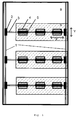
- Figure 1 shows a top view of a greenhouse with arrangement the device according to the invention Operating conditions.
- the longitudinal rails 1 are with Longitudinal drive means 2 provided.
- the perpendicular to the Longitudinal rails 1 arranged transverse rails 3 are provided with lamps 4.
- the cross rails 3 are in this embodiment above the planting tables A of the greenhouse arranged.
- the area marked with B represents represents the aisle area in the greenhouse.
- the cross rails 3 can along the axis of the longitudinal tracks 1 be moved. This direction of movement or the Y axis is identified by the double arrow Y.
- Illuminants 4 can along the axis of the cross rails 3 are moved. This direction of movement or X axis is identified by the double arrow X.
- Figure 2 is a top view of a greenhouse Arrangement of the device according to the invention in the "parking position" shown.
- the longitudinal drive means 2 With the help of the longitudinal drive means 2, the cross rails 3 with the mounted on it Illuminants 4 and the transverse drive means 5 pushed together along the longitudinal running rail (Y axis) 1, so that they are no longer above the planting tables A but are arranged above the gangway B.
- FIG 3 is the side view of that shown in Figure 2 Arrangement of the device according to the invention in "Parking position" shown.
- the cross rails 3 with the lamps 4 are located no longer above the table surface A, but are using the longitudinal drive means 2 along the Longitudinal track 1 (Y axis) in the area of the aisle area B pushed.
- Y axis Longitudinal track 1
- XY plane XY plane
- the Rails 1 and 3 can be along the axis of this Track 6 can be moved up and down. This direction of movement or Z-axis is determined by the Double arrow Z marked.
- the longitudinal drive means 2 are interconnected via cables 7.
- Figure 4 shows the side view of the arrangement of the invention Device in "parking position" with vertical stacked lamps 4.
- Figure 5 shows the side view of the arrangement of the invention Device in "parking position" with Illuminants 4 arranged under planting tables A. are.
- the cross rails 3 with the lamps 4 are along the longitudinal track 1 according to the the double arrow a marked direction on the Slide rail 6 and by this according to the the double arrow b marked direction to Longitudinal slide rail 1, which is below the Planting tables that are equipped with casters.
- the present invention relates to a device for flexible lighting of rooms comprising tracks and lamps, which is characterized in that it contains at least two parallel longitudinal tracks 1 with longitudinal drive means 2, and at least one transverse track 3, both of which Connects longitudinal tracks 1 to each other and can be moved along the longitudinal tracks 1 by means of the longitudinal drive means 2, the transverse track 3 being equipped with lamps 4 and transverse drive means 5 for moving the lamps 4 along the transverse track 3.
- the transverse running rails 3 are arranged perpendicular to the longitudinal running rails 1.
- a diamond-shaped lattice structure, in which the transverse rails are not arranged at right angles to the longitudinal rails 1, is also possible.
- the lamps 4 can be moved to the desired position, in which lighting is desired, due to the variable attachment to mobile running rails. At the same time, however, they can also be removed from a position in which the lamps have an adverse effect on radiation (shading of the sunlight) or an area of the room becomes inaccessible by the lamps. There is no need for time-consuming dismantling and reinstallation, which would be necessary with permanently installed lamps.
- the term illuminant is intended to include both the lamp, such as, for example, the incandescent lamp or halogen lamp, and the suspension device, such as, for example, the lamp holder or the lampshade.
- the lamps can be moved both along the longitudinal running rail 1 and along the transverse running rails 3.
- the movement of the illuminants 4 along the longitudinal running rail 1 is made possible by moving the transverse running rail 3, on which the illuminants 4 are fastened, by the longitudinal drive means 2 of the longitudinal running rail 1.
- the displacement of the lamps 4 along the cross rail 3 is carried out with the aid of the cross drive means 5.
- the position of the illuminants 4 can therefore be varied freely within the XY plane, which is formed by the longitudinal running rails 1 and the transverse running rails 3.
- the number of longitudinal rails 1 and cross rails 3 can be modified.
- the number of longitudinal running rails 1 should be at least two and that of the transverse running rails 3 should be at least one in order to ensure a stable suspension of the lamps 4.
- the device according to the invention is preferably suitable for lighting in greenhouses. However, it can also be advantageous for illuminating, for example, shopping malls or production halls, the rooms of which are illuminated with sunlight in addition to artificial illuminants. In rooms that are only illuminated using artificial light sources, such as B. production halls or museums, the device according to the invention can be used to make the lighting variable depending on the current need. This can lead to a saving of lamps and secondly, optimal lighting of the room can first be determined experimentally.
- this device comprises Drive means and / or rails 6, which or with which the illuminants 4 perpendicular to XY plane through the longitudinal rails 1 and the Cross rails 3 is clamped, are moved.
- drive means include, for example, cable pulls, which move the lamps 4 down or up.
- the illuminants 4 can also along the Running rails 6 (see Fig. 3) perpendicular to the XY plane through the longitudinal running rails 1 and the transverse running rail 3 is formed, can be moved up or down.
- the bulbs can therefore within the XYZ axes formed spatial planes freely selectable become.
- the illuminants 4 particularly space-saving vertically one above the other on the Track 6 are arranged.
- the illuminants 4 are often reflective Provide material to use the scattered light to reach.
- This reflective material e.g. shading fabric from aluminum threads
- the reflective fabric is when moving the lamp 4 in the "Parking position" contracted and when using the Illuminant 4 again over the area to be illuminated stretched by pulling the illuminants 4 apart.
- An advantageous embodiment of the device comprises drive means, which are controlled by light sensors. This enables defined and constant lighting conditions about the selectable positioning of the Illuminant 4 in a room or directly from objects and set automatically. Is used by the light sensors for example in a room that is predominantly lit by natural sunlight, a Reduction of the desired or required light radiation detected, so the artificial Compensate for this by placing them precisely in the bulb Area to be moved where sunlight is not sufficient. If the natural sun exposure then increases again and the light sensors exceed detect the desired light radiation, the bulbs can be removed from the "overexposed" Area pushed into the "parking position" (see Fig. 2 and 3) become. For the electrical control of the drive means the necessary power cables must be hung that they carried with the drive means can be.
- the cross rails 3 with the longitudinal rails 1 longitudinal drive means 2 attached are at the connection points the cross rails 3 with the longitudinal rails 1 longitudinal drive means 2 attached, so that each cross rail 3 individually or together with further cross rails along the longitudinal rails 1 can be moved.
- a drive can the device, for example, trolleys, Cable winches, cable or chain hoists or electrically operated Drive motors include.
- the special advantage the cable or chain hoists is that these Drive means can be implemented in a technically simple manner and little or no additional Consume energy.
- the drive means such.
- B. Trolleys can be connected to each other by rotating cables are and driven by a common motor become. It may be enough, only with the foremost trolley on a running track to provide a drive and the remaining trolleys with flexible spacers (e.g. chains) with each other connect to.
- the cross rails 3 are equipped with at least one illuminant 4. Depending on the light requirement and light intensity of the illuminants, however, any number of illuminants can be attached to the cross rails 3. In greenhouse technology, a lamp with a power of approx. 400 W is usually used, so that a light intensity of approx. 40 W per m 2 occurs on the surface to be exposed.
- the device can comprise all commercially available lamps, such as incandescent lamps, mercury vapor lamps, halogen lamps, special plant light lamps or also neon lamps, as illuminants.
- the running rails can be in an advantageous embodiment the device according to the invention as busbars be designed.
- the power supply for the lamps 4 on the movable cross rails 3 and possibly the longitudinal drive means 2, otherwise done with power cables is simplified.
- the tracks are made of aluminum, Stainless steel or other statically stable material. This ensures a stable attachment of the lamps on the running rails as well as an even and flawless Function of the drive means of the running rails.
- the lamps 4 can Because of the variable attachment on mobile tracks moved to the desired position as required become.
- the lamps 4 can both along the Longitudinal rails 1 as well as along the transverse rails 3 are moved.
- the movement of the lamps 4 along the longitudinal track 1 is by moving the transverse guide rail 3 on which the lamps 4 are attached by the longitudinal drive means 2 of Longitudinal track 1 allows.
- Moving the Illuminant 4 along the cross rail 3 is with Helped by the transverse drive means 5.
- the position the illuminant 4 can thus within the XY plane through the longitudinal rails 1 and the Cross rails 3 is formed, varied freely and in be moved to the position where the lighting is required is.
- the illuminants 4 for example with the help of cables or another Track 6, perpendicular to the XY plane up or be moved down. This makes it possible Position the illuminant anywhere in the room in three dimensions.
- This Embodiment is particularly in light-dependent production processes beneficial to a high area-specific Productivity depends on how z. B. growing plants in greenhouses. Here it is it is particularly important that both artificial light and natural sunlight is also effective for production is implemented by plants and effective use of the available space. In the The lamps are so used with solar radiation postponed that they blocked the natural radiation by shadowing do not interfere. You will be in one "Parking position" shifted (see Figs. 2 to 5) i.e.
- the cross rails 3 with the lamps 4 can in a further advantageous embodiment the method on a running rail 6 vertically can be arranged one above the other (see Fig. 4). hereby a particularly space-saving "parking position" is made possible.
- the cross rails 3 with the lamps attached to it 4 pushed under the surface by the solar radiation is illuminated, such as. B. the planting tables A (see Fig. 5). This means there is no need for additional space for the "parking position" of the illuminants 4 is made available and can only be used as a production area be used. Instead, the otherwise unused Area under the planting tables A, which also designed to be mobile with castors can be useful for "parking" the illuminant 4 can be used.
- the drive means controlled by light sensors.
- a drive means per lamp and one drive per connection point the cross rail 3 with the longitudinal rails 1, the illuminants 4 both individually and can also be moved in groups as needed.
- a drive has the use of trolleys, rope / chain hoists, Cable winches and / or electric drive motors proven suitable.
- Cross rails with ⁇ 1 illuminant 4 used In an advantageous embodiment of the method Cross rails with ⁇ 1 illuminant 4 used.
- a lamp with a power of 400 W proved to be suitable.
- Can be used as illuminants for example incandescent lamps, mercury vapor lamps, halogen lamps, Plant light lamps or neon lamps are used become.
- Running rails used which at the same time as busbars are designed.
- the power supply of the Illuminant and possibly the drive means can thereby be simplified. It should be beneficial Execution of the procedure rails Aluminum, stainless steel or other statically stable material be used, the stable attachment of the illuminant and perfect movement of the drive means guarantee.
Landscapes
- Life Sciences & Earth Sciences (AREA)
- Engineering & Computer Science (AREA)
- General Engineering & Computer Science (AREA)
- Environmental Sciences (AREA)
- Biodiversity & Conservation Biology (AREA)
- Botany (AREA)
- Ecology (AREA)
- Forests & Forestry (AREA)
- Non-Portable Lighting Devices Or Systems Thereof (AREA)
- Cultivation Of Plants (AREA)
- Securing Globes, Refractors, Reflectors Or The Like (AREA)
Applications Claiming Priority (2)
| Application Number | Priority Date | Filing Date | Title |
|---|---|---|---|
| DE10237062A DE10237062A1 (de) | 2002-08-09 | 2002-08-09 | Vorrichtung und Verfahren zur flexiblen Beleuchtung von Räumen |
| DE10237062 | 2002-08-09 |
Publications (2)
| Publication Number | Publication Date |
|---|---|
| EP1388708A2 true EP1388708A2 (fr) | 2004-02-11 |
| EP1388708A3 EP1388708A3 (fr) | 2006-05-24 |
Family
ID=30128837
Family Applications (1)
| Application Number | Title | Priority Date | Filing Date |
|---|---|---|---|
| EP03015424A Withdrawn EP1388708A3 (fr) | 2002-08-09 | 2003-07-09 | Dispositif et procédé d'éclairage flexible pour l'illumination de locaux |
Country Status (2)
| Country | Link |
|---|---|
| EP (1) | EP1388708A3 (fr) |
| DE (1) | DE10237062A1 (fr) |
Cited By (9)
| Publication number | Priority date | Publication date | Assignee | Title |
|---|---|---|---|---|
| WO2005027621A1 (fr) * | 2003-09-19 | 2005-03-31 | David Knelsen Dyck | Dispositif d'eclairage mobile reglable en hauteur pour une serre |
| NL1031466C2 (nl) * | 2006-03-30 | 2007-10-03 | Pll Systems B V | Inrichting voor het beïnvloeden van de groei van in een ruimte dan wel op een perceel opgestelde gewassen. |
| CN102771345A (zh) * | 2012-07-31 | 2012-11-14 | 中国农业科学院农业环境与可持续发展研究所 | 一种使用led光源栽培植物的方法及该方法使用的装置 |
| CN109328517A (zh) * | 2018-08-15 | 2019-02-15 | 江苏绿岩生态技术股份有限公司 | 一种利用类壤土基质喷播技术进行沙地治理的方法 |
| RU191027U1 (ru) * | 2018-12-03 | 2019-07-22 | Общество с ограниченной ответственностью "Горизонт" | Светодиодный светильник для растений с системой регулируемых креплений |
| CN111750324B (zh) * | 2020-06-22 | 2021-12-14 | 江苏创一佳科技股份有限公司 | 一种恒照度照明装置及智能调光方法 |
| US11589520B2 (en) * | 2016-09-15 | 2023-02-28 | Ocado Innovation Limited | Growing systems and methods |
| CN116867718A (zh) * | 2021-03-29 | 2023-10-10 | 亨乃尔有限公司 | 用于指示储物的设备和具有这种设备的储物架 |
| CN117006449A (zh) * | 2023-09-13 | 2023-11-07 | 华侨大学 | 一种整体张拉磁悬浮灯具塔装置 |
Families Citing this family (3)
| Publication number | Priority date | Publication date | Assignee | Title |
|---|---|---|---|---|
| FI124081B (fi) * | 2009-02-04 | 2014-03-14 | Assimilight Oy Ltd | Menelmä ja järjestely kasvihuonekasvien valaisemiseksi |
| DE102009011714B4 (de) * | 2009-03-09 | 2019-01-31 | Wofi Leuchten Wortmann & Filz Gmbh & Co. Kg | Beweglicher Leuchtenträger |
| CN112715199A (zh) * | 2020-12-28 | 2021-04-30 | 安徽世林照明股份有限公司 | 一种植物照明灯具及系统 |
Family Cites Families (9)
| Publication number | Priority date | Publication date | Assignee | Title |
|---|---|---|---|---|
| DE189597C (fr) * | ||||
| US1712650A (en) * | 1928-03-10 | 1929-05-14 | Frederick P Clark | Safety device |
| US2905806A (en) * | 1956-04-09 | 1959-09-22 | Gilbert H Tunney | Studio lighting system |
| DE2161334A1 (de) * | 1971-12-10 | 1973-06-14 | Eisenberg Hans Jochen | Deckenbeleuchtungsanlage fuer grosshallen, z.b. schwimmhallen, sporthallen, messehallen oder dgl |
| AT341617B (de) * | 1973-03-12 | 1978-02-27 | Ruthner Othmar | Beleuchtungseinrichtung fur kulturanlagen, insbesondere gewachshauser |
| DE3445622A1 (de) * | 1984-12-14 | 1986-06-19 | BCL-Lichttechnik Inh. Claudia C. Berger, 8000 München | Aufhaengung fuer ein beleuchtungsgeraet |
| DE4124794C2 (de) * | 1991-07-26 | 1993-11-11 | Werner Mielke | Beleuchtungsanlage mit verfahrbaren, eine Dimm- und Schalteinheit enthaltenden Leuchtkörpern |
| DE19608224A1 (de) * | 1996-03-04 | 1997-09-11 | Waldmann Gmbh & Co Herbert | Beleuchtungsanordnung mit von einem Lichtsensor gesteuerten Lichtquellen |
| US5993030A (en) * | 1998-02-03 | 1999-11-30 | Barcel; Barton J. | Travelling lighting system |
-
2002
- 2002-08-09 DE DE10237062A patent/DE10237062A1/de not_active Ceased
-
2003
- 2003-07-09 EP EP03015424A patent/EP1388708A3/fr not_active Withdrawn
Non-Patent Citations (1)
| Title |
|---|
| None |
Cited By (9)
| Publication number | Priority date | Publication date | Assignee | Title |
|---|---|---|---|---|
| WO2005027621A1 (fr) * | 2003-09-19 | 2005-03-31 | David Knelsen Dyck | Dispositif d'eclairage mobile reglable en hauteur pour une serre |
| NL1031466C2 (nl) * | 2006-03-30 | 2007-10-03 | Pll Systems B V | Inrichting voor het beïnvloeden van de groei van in een ruimte dan wel op een perceel opgestelde gewassen. |
| CN102771345A (zh) * | 2012-07-31 | 2012-11-14 | 中国农业科学院农业环境与可持续发展研究所 | 一种使用led光源栽培植物的方法及该方法使用的装置 |
| US11589520B2 (en) * | 2016-09-15 | 2023-02-28 | Ocado Innovation Limited | Growing systems and methods |
| CN109328517A (zh) * | 2018-08-15 | 2019-02-15 | 江苏绿岩生态技术股份有限公司 | 一种利用类壤土基质喷播技术进行沙地治理的方法 |
| RU191027U1 (ru) * | 2018-12-03 | 2019-07-22 | Общество с ограниченной ответственностью "Горизонт" | Светодиодный светильник для растений с системой регулируемых креплений |
| CN111750324B (zh) * | 2020-06-22 | 2021-12-14 | 江苏创一佳科技股份有限公司 | 一种恒照度照明装置及智能调光方法 |
| CN116867718A (zh) * | 2021-03-29 | 2023-10-10 | 亨乃尔有限公司 | 用于指示储物的设备和具有这种设备的储物架 |
| CN117006449A (zh) * | 2023-09-13 | 2023-11-07 | 华侨大学 | 一种整体张拉磁悬浮灯具塔装置 |
Also Published As
| Publication number | Publication date |
|---|---|
| EP1388708A3 (fr) | 2006-05-24 |
| DE10237062A1 (de) | 2004-02-19 |
Similar Documents
| Publication | Publication Date | Title |
|---|---|---|
| EP0242568B1 (fr) | Dispositif pour la création de lieux de travail ayant des connexions d'alimentation diverses | |
| EP1388708A2 (fr) | Dispositif et procédé d'éclairage flexible pour l'illumination de locaux | |
| EP3014169B1 (fr) | Luminaire destiné à être utilisé dans un système de rail d'éclairage ainsi que système de rail d'éclairage | |
| DE2709541A1 (de) | Haengedeckenanordnung | |
| DE3147510A1 (de) | Abgehaengte decke mit integriertem beleuchtungskoerper, beleuchtungskoerper und verfahren zum bau einer abgehaengten decke mit beleuchtungskoerper | |
| EP1066188A1 (fr) | Dispositif rotatif | |
| EP3293441A1 (fr) | Luminaire | |
| DE20214879U1 (de) | Beleuchtungsvorrichtung | |
| EP0138746A1 (fr) | Armature avec source lumineuse linéaire accessoire | |
| DE69210382T2 (de) | Beleuchtungs- und Hängevorrichtung in Einzelausführung und in modularer Bauweise zum Aufhängen von Objekten | |
| DE867473C (de) | Einrichtung zur kuenstlichen Beleuchtung von Pflanzen in Gewaechshaeusern | |
| EP2330344B1 (fr) | Dispositif d'éclairage modifiable | |
| DE3434410A1 (de) | Elektrische haengelampe | |
| EP3876364B1 (fr) | Système d'éclairage sur rail | |
| DE202023105901U1 (de) | Leuchtsystem zur Beleuchtung eines Arbeitsbereichs einer Hebebühne | |
| EP0469179A1 (fr) | Système d'éclairage modulaire | |
| EP3135080A1 (fr) | Système et procédé d'éclairage de zones de travail | |
| DE102020119850A1 (de) | Deckenleuchte | |
| DE102018121898A1 (de) | Sportstättenbeleuchtung zur Förderung des Rasenwachstums | |
| AT240977B (de) | Installationskanal für Lichtbänder | |
| DE202015103002U1 (de) | Leuchtenanordnung | |
| DE10056325A1 (de) | Vorrichtung zur Ausleuchtung von Crashtest-Anlagen | |
| DE202023102528U1 (de) | Lichtsteuerungssystem für einen Lichttunnel | |
| DE3918193A1 (de) | Moebelstueck | |
| EP4166841A1 (fr) | Luminaire extérieur à éclairage ambiant contrôlable |
Legal Events
| Date | Code | Title | Description |
|---|---|---|---|
| PUAI | Public reference made under article 153(3) epc to a published international application that has entered the european phase |
Free format text: ORIGINAL CODE: 0009012 |
|
| AK | Designated contracting states |
Kind code of ref document: A2 Designated state(s): AT BE BG CH CY CZ DE DK EE ES FI FR GB GR HU IE IT LI LU MC NL PT RO SE SI SK TR |
|
| AX | Request for extension of the european patent |
Extension state: AL LT LV MK |
|
| PUAL | Search report despatched |
Free format text: ORIGINAL CODE: 0009013 |
|
| AK | Designated contracting states |
Kind code of ref document: A3 Designated state(s): AT BE BG CH CY CZ DE DK EE ES FI FR GB GR HU IE IT LI LU MC NL PT RO SE SI SK TR |
|
| AX | Request for extension of the european patent |
Extension state: AL LT LV MK |
|
| 17P | Request for examination filed |
Effective date: 20060810 |
|
| AKX | Designation fees paid |
Designated state(s): AT BE BG CH CY CZ DE DK EE ES FI FR GB GR HU IE IT LI LU MC NL PT RO SE SI SK TR |
|
| 17Q | First examination report despatched |
Effective date: 20070327 |
|
| GRAP | Despatch of communication of intention to grant a patent |
Free format text: ORIGINAL CODE: EPIDOSNIGR1 |
|
| RIN1 | Information on inventor provided before grant (corrected) |
Inventor name: JAHNKE, SIEGFRIED |
|
| STAA | Information on the status of an ep patent application or granted ep patent |
Free format text: STATUS: THE APPLICATION HAS BEEN WITHDRAWN |
|
| 18W | Application withdrawn |
Effective date: 20081022 |