EP1389416A2 - Dispositif de nettoyage et dispositif soufflant de nettoyage pour une moissonneuse-batteuse - Google Patents
Dispositif de nettoyage et dispositif soufflant de nettoyage pour une moissonneuse-batteuse Download PDFInfo
- Publication number
- EP1389416A2 EP1389416A2 EP03102038A EP03102038A EP1389416A2 EP 1389416 A2 EP1389416 A2 EP 1389416A2 EP 03102038 A EP03102038 A EP 03102038A EP 03102038 A EP03102038 A EP 03102038A EP 1389416 A2 EP1389416 A2 EP 1389416A2
- Authority
- EP
- European Patent Office
- Prior art keywords
- cleaning
- air flow
- openings
- cleaning device
- air
- Prior art date
- Legal status (The legal status is an assumption and is not a legal conclusion. Google has not performed a legal analysis and makes no representation as to the accuracy of the status listed.)
- Withdrawn
Links
Images


Classifications
-
- A—HUMAN NECESSITIES
- A01—AGRICULTURE; FORESTRY; ANIMAL HUSBANDRY; HUNTING; TRAPPING; FISHING
- A01F—PROCESSING OF HARVESTED PRODUCE; HAY OR STRAW PRESSES; DEVICES FOR STORING AGRICULTURAL OR HORTICULTURAL PRODUCE
- A01F12/00—Parts or details of threshing apparatus
- A01F12/44—Grain cleaners; Grain separators
- A01F12/444—Fanning means
-
- A—HUMAN NECESSITIES
- A01—AGRICULTURE; FORESTRY; ANIMAL HUSBANDRY; HUNTING; TRAPPING; FISHING
- A01F—PROCESSING OF HARVESTED PRODUCE; HAY OR STRAW PRESSES; DEVICES FOR STORING AGRICULTURAL OR HORTICULTURAL PRODUCE
- A01F12/00—Parts or details of threshing apparatus
- A01F12/44—Grain cleaners; Grain separators
- A01F12/446—Sieving means
Definitions
- the invention relates to a cleaning device for a Combine harvester, with a sieve box, which is a main top sieve and a front upper sieve, which is upstream of the main upper sieve is arranged and threshed components of Picking up crop, as well as a cleaning blower for one Combine cleaning device operating within a Is arranged, the openings for receiving air and Has openings through which an air flow to a sieve box can be fed, wherein the cleaning fan is a variety axially extending blades extending from a shaft extend radially outward.
- Agricultural combine harvesters harvest crop from a field thresh it to remove the large parts of the crop separate and clean smaller components of the crop the smaller components to separate the chaff from the grain.
- the combine can be used with different headers be equipped, including (rigid or flexible) Cutting units for grain harvesting, corn picking, headers for Row crop or swather platforms, depending on the crop and the harvesting method used by the farmer.
- the threshing assembly of the combine can be similar different types can be configured, including one conventional, transverse threshing drum with one Concave or a rotor threshing system that is either axial or is aligned transversely.
- the Separate assemblies conventional straw walkers or Have rotor assemblies.
- the cleaning system removes the chaff from the grain.
- the Cleaning system typically includes a screen box and a Cleaning fan.
- the smaller crop components from Threshing assembly and separation assembly become the screen box fed.
- the screen box is typically with a top screen and a bottom sieve.
- the top and bottom sieves have transverse slats that define openings. The heavier small grains fall through the lamellas shaped openings in the top and bottom sieves.
- the from Airflow generated by the cleaning fan blows the chaff on the Rear of the combine to the outside.
- the object on which the invention is based is seen in to provide a cleaning device of a combine harvester, which is suitable for high throughputs.
- the screen box of the cleaning device of a combine harvester equipped with a front upper sieve, which is upstream of the Main top screen is arranged.
- the front upper sieve has one upstream, closed area and one with Areas provided with openings downstream.
- the upstream lying area is inclined upwards and the downstream area Area is sloping down.
- the front top wire is oriented to allow airflow from a cleaning fan below the closed, upstream area along and through the down inclined, downstream area flows upwards.
- the downstream, apertured area can be marked with preferably adjustable slats, by which the airflow goes through. Grain and heavier particles fall through the slats on a baffle, which these components feed to a main sieve.
- a cleaning blower proposed that within a housing with one or a plurality of airflow openings is arranged through which one Airflow reaches the sieve box.
- a first airflow opening can create a first airflow along the front top wire lead while a second airflow opening a second Directs airflow along a baffle.
- the Cleaning blower includes a plurality of radial and axially extending blades for air delivery. It will suggested that inserts that contain air barriers or barriers form, are attached to the cleaning fan. Prevent you axial air currents, so that one over the width of the Cleaning blower receives approximately constant strong air flow.
- the Inserts can be provided with openings that correspond to the axial Limit air flow across the blades.
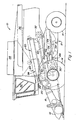
- FIG. 1 shows a side view of a self-propelled agricultural combine 10.
- the Combine harvester 10 includes a frame 12 with wheels 14 for Supporting and propelling the combine 10.
- the frame 12 comprises two axially extending side plates 15, between which the various processing assemblies for the Crop are arranged.
- a cutter 16 is on the Front of the combine 10 attached and leads harvested Well an inclined conveyor 18 too.
- the feeder 18 contains a conveyor, the threshing, separating and To supply cleaning assemblies between the Side plates 15 of the combine 10 are arranged.
- the present invention than on a combine with an axial arranged separating device is disclosed attached also on combine harvesters with threshing drums and straw walkers and other combine configurations with a cleaning device be used.
- the inclined conveyor 18 the harvested crop of a transversely extending guide drum 20 to which the goods pass through an inlet transition area 22 axial threshing and separating assembly 24 supplies.
- Grain and chaff are one of the axial threshing and separating assembly 24 Cleaning assembly 26 supplied.
- the cleaning assembly 26 leads the clean grain to a grain tank 28 and the Chaff is cleaned by the blower 30 on the back of the Combine blown out.
- Crop that is neither grain nor Chaff is from the axial threshing and separating assembly 24 a transversely arranged guide drum 32, which the Material on the back of the combine 10 pushes out. Clean grain temporarily stored in the grain tank 28 can pass through Operation of an unloading auger 36 by an operator be unloaded in the operator's cab 34.
- the grain-rich mixture floats to and fro with you Apertured downstream area 48 of the front Upper sieve 42.
- An air flow from cleaning fan 30 is through a first airflow opening 50 onto the lower surface of the closed upstream region 46 of the front Upper sieve 42 passed.
- the one with openings, upstream lying area 48 is transverse with a multitude of itself extending slats 52 provided the openings define through which the heavier grain can fall.
- the Airflow from the first airflow opening 50 follows the lower one Surface of the closed, upstream region 46, until it hits the bottom surface of the downstream area 48 hits.
- the downward slope of the downstream lying area 48 and the slats 52 conduct part of the Airflow up through downstream region 48 to blow the chaff back and the grain between the Let slats 52 pass.
- the baffle 54 is also with the Sieve box moves back and forth and is equipped with steps, the grain picked up by the baffle plate 54 and the chaff Drive to the top and back of finger sticks 56.
- the grain falls either through the finger rods 56 on the lower sieve 58 or that Grain and chaff are placed along the fingersticks 56 on the Main top screen 44 promoted.
- the main top screen 44 and that Bottom sieve 58 further cleans the grain by removing chaff from the grain release them so that they are at the rear of the combine 10 by the air flow generated by the cleaning fan 30 can be blown out.
- the mixture with a high proportion of chaff from the separating section 60 becomes the front upper sieve 42 fed through a bottom 62. Because of the Airflow passing through the open, downstream section 48 of the front upper wire 42 flows, a part of this reaches Mixture with a high proportion of chaff not the front upper sieve 42 and is blown backwards directly onto the main top sieve 44.
- the cleaning fan 30 is arranged in a housing 64 which the first airflow opening 50 defines a first To direct airflow below the front top wire 42, and one second airflow opening 66 to a second airflow under the Baffle plate 54 and lead to the main top screen 44. Approximately eighty percent of the air volume of the cleaning fan 30 flows through the second airflow opening 66 while the remaining twenty percent of the air volume through the first Airflow opening 50 flow.
- Housing 64 includes one circumferential wall, which is between the side plates 15th extends. The side panels 15 have openings through the air conveyed into the lateral ends of the cleaning fan 30 can be.
- the peripheral wall with the upstream first airflow opening 50 arranged openings 68 equipped to radially supply air to the cleaning fan.
- the cleaning fan 30 includes a plurality of crosswise (i.e. H. with respect to its longitudinal axis axially) and radially extending Blades 70 that extend through a series of radially Elements 74 are attached to a central shaft 72.
- the Cleaning blower 30 defines a cylinder with first and second lateral ends, which are in the vicinity of the side plates 15 of the combine 10 are arranged. Typically that is largest air flow for a cleaning fan 30 (across to Considered travel direction) at its center with a reduced Airflow at the side ends because part of the airflow moves across the blades 70 if that Cleaning blower 30 promotes air.
- first and second inserts 80 are close to that side ends of the cleaning fan 30 attached to air to hold these ends through the openings in the Side panels is retracted. In this way, the Inserts 80 a more uniform in the lateral direction Airflow over the cleaning fan 30 ready.
- the stakes 80 form an air dam with openings 82 which define the lateral (i.e. H. with respect to the longitudinal axis of the cleaning fan 30 axially) Limit air flow along the blades 70.
- the stakes 80 are flat rings.
- the number of openings 82 corresponds to that Number of blades 70, so some air laterally over all Blades 70 flows.
Landscapes
- Life Sciences & Earth Sciences (AREA)
- Environmental Sciences (AREA)
- Threshing Machine Elements (AREA)
- Combines (AREA)
- Apparatuses For Bulk Treatment Of Fruits And Vegetables And Apparatuses For Preparing Feeds (AREA)
- Structures Of Non-Positive Displacement Pumps (AREA)
Applications Claiming Priority (2)
| Application Number | Priority Date | Filing Date | Title |
|---|---|---|---|
| US209400 | 2000-06-01 | ||
| US10/209,400 US6773343B2 (en) | 2002-07-31 | 2002-07-31 | Front chaffer and cleaning fan |
Publications (2)
| Publication Number | Publication Date |
|---|---|
| EP1389416A2 true EP1389416A2 (fr) | 2004-02-18 |
| EP1389416A3 EP1389416A3 (fr) | 2008-11-05 |
Family
ID=30770590
Family Applications (1)
| Application Number | Title | Priority Date | Filing Date |
|---|---|---|---|
| EP03102038A Withdrawn EP1389416A3 (fr) | 2002-07-31 | 2003-07-08 | Dispositif de nettoyage et dispositif soufflant de nettoyage pour une moissonneuse-batteuse |
Country Status (4)
| Country | Link |
|---|---|
| US (2) | US6773343B2 (fr) |
| EP (1) | EP1389416A3 (fr) |
| AR (1) | AR040741A1 (fr) |
| BR (1) | BR0302504B1 (fr) |
Cited By (3)
| Publication number | Priority date | Publication date | Assignee | Title |
|---|---|---|---|---|
| EP1932421A1 (fr) * | 2006-12-13 | 2008-06-18 | CNH Belgium N.V. | Axe et enveloppe de ventilateur de nettoyage intégrées pour moissonneuse agricole |
| WO2008149233A3 (fr) * | 2007-06-08 | 2009-03-19 | Agco Do Brasil Com E Ind Ltda | Moissonneuses-batteuses |
| CN104568588A (zh) * | 2013-10-17 | 2015-04-29 | 珠海格力电器股份有限公司 | 嵌件的橡胶体用检测装置 |
Families Citing this family (31)
| Publication number | Priority date | Publication date | Assignee | Title |
|---|---|---|---|---|
| BRPI0413633A (pt) * | 2003-08-19 | 2006-10-17 | James Straeter | sapata de máquina combinada de ceifar e debulhar controlada por fluxo de ar |
| DE102005010592A1 (de) * | 2005-03-04 | 2006-10-19 | Claas Selbstfahrende Erntemaschinen Gmbh | Mähdrescher |
| DE102005026608A1 (de) * | 2005-06-09 | 2007-01-04 | Deere & Company, Moline | Reinigungseinrichtung für einen Mähdrescher |
| US7685530B2 (en) * | 2005-06-10 | 2010-03-23 | T-Mobile Usa, Inc. | Preferred contact group centric interface |
| US20090280876A1 (en) * | 2008-05-08 | 2009-11-12 | Yoder Denver R | Cleaning fan housing with a clean-out access door |
| US8626400B2 (en) * | 2008-05-29 | 2014-01-07 | Deere & Company | Grain cleaning system |
| US8221064B2 (en) * | 2008-11-18 | 2012-07-17 | Cnh America Llc | Transverse fan assembly having a supplementary air feed inlet for infill of air flow deficiencies to effect a desired output air flow pattern, and method of use thereof |
| US8062109B1 (en) | 2010-08-27 | 2011-11-22 | Deere & Company | Dust suppressor for combine harvester feederhouse |
| WO2013016473A1 (fr) * | 2011-07-27 | 2013-01-31 | Agco Corporation | Géométrie pour la régulation de la vitesse de l'air dans une moissonneuse batteuse |
| US20130157732A1 (en) * | 2011-12-14 | 2013-06-20 | James M. Kopriva | Cascade Pan |
| US8801512B2 (en) * | 2011-12-19 | 2014-08-12 | Agco Corporation | Method for measuring air efficiency and efficacy in a combine harvester |
| US8651927B1 (en) * | 2012-09-13 | 2014-02-18 | Cnh America Llc | Combine harvester sieve assembly with an integrated air cleaning system |
| US8608534B1 (en) * | 2012-09-25 | 2013-12-17 | Agco Corporation | Rolled secondary cut off in air distribution system of a combine harvester |
| GB201221347D0 (en) * | 2012-11-28 | 2013-01-09 | Agco As | Crop processing apparatus in a combine harvester |
| US9033779B2 (en) * | 2012-11-29 | 2015-05-19 | Cnh Industrial America Llc | Air diverter for a cleaning system of a combine harvester |
| US8821229B2 (en) | 2012-12-06 | 2014-09-02 | Cnh Industrial America Llc | Grain cleaning system for an agricultural combine |
| BE1021154B1 (nl) * | 2013-07-02 | 2016-10-26 | Cnh Industrial Belgium Nv | Maaidorser met meertrapsgraanvoorbereiding |
| GB201319215D0 (en) * | 2013-10-31 | 2013-12-18 | Agco As | Grain seperating apparatus in a combine harvester |
| US9526211B2 (en) * | 2014-02-28 | 2016-12-27 | Cnh Industrial America Llc | System and method of controlling airflow characteristics in an agricultural harvester |
| US9750192B2 (en) | 2014-08-29 | 2017-09-05 | Deere & Company | Integrated fan and axle arrangement for an agricultural vehicle |
| BE1022893B1 (nl) * | 2015-05-29 | 2016-10-07 | Cnh Industrial Belgium Nv | Graanreinigingssysteem met verbeterde luchtstroming en aanvullende valstap om de graanreinigingsprestaties te verbeteren |
| CN208462428U (zh) * | 2015-08-28 | 2019-02-05 | 凯斯纽荷兰(中国)管理有限公司 | 农业收割机 |
| CN106385999B (zh) * | 2016-08-29 | 2019-06-28 | 江苏大学 | 切流与纵轴流装置脱粒分离负荷的自适应调控系统 |
| US10219439B1 (en) * | 2017-08-14 | 2019-03-05 | Cnh Industrial America Llc | Harvester cleaning system with conveyor enhanced cascades |
| US10863672B2 (en) | 2017-11-06 | 2020-12-15 | Deere & Company | Radio frequency measurement device for measuring harvested agricultural material |
| US10871458B2 (en) | 2017-11-06 | 2020-12-22 | Deere & Company | Radio frequency measurement device for measuring grain loss |
| US11291160B2 (en) * | 2018-05-25 | 2022-04-05 | Cnh Industrial America Llc | Agricultural harvester and a dust extractor for the agricultural harvester |
| US11013175B2 (en) | 2018-07-26 | 2021-05-25 | Deere & Company | Grain loss apparatus for a grain harvesting vehicle |
| US10966371B2 (en) * | 2018-11-05 | 2021-04-06 | Cnh Industrial America Llc | Cleaning system for a combine |
| US11540443B2 (en) | 2019-01-31 | 2023-01-03 | Deere & Company | System and method for measurement of harvested material in a cleaning assembly |
| WO2025038090A1 (fr) * | 2023-08-17 | 2025-02-20 | Zeigler Alexis | Moissonneuse-batteuse simplifiée |
Family Cites Families (33)
| Publication number | Priority date | Publication date | Assignee | Title |
|---|---|---|---|---|
| US896698A (en) * | 1903-11-16 | 1908-08-18 | Gen Electric | Arc-lamp. |
| US875550A (en) * | 1906-09-05 | 1907-12-31 | James Mccorkell | Threshing-machine. |
| US3109433A (en) * | 1960-10-25 | 1963-11-05 | Claas Reinhold | Threshing mechanism, particularly for combine harvesters |
| FR1441981A (fr) * | 1965-07-26 | 1966-06-10 | Massey Ferguson Ltd | Moissonneuse-batteuse munie d'un ventilateur à écoulement transversal |
| US3402720A (en) * | 1965-08-06 | 1968-09-24 | Int Harvester Co | Fan screen construction for combines |
| US3469773A (en) * | 1968-07-12 | 1969-09-30 | Int Harvester Co | Fan for combine |
| US3664349A (en) * | 1969-12-19 | 1972-05-23 | Univ Iowa State Res Found | Combine cleaning blower |
| US3635588A (en) * | 1970-02-16 | 1972-01-18 | Robert W Lester | Detent mechanism for retaining vanes in a circularly driven impeller |
| US3638659A (en) * | 1970-04-03 | 1972-02-01 | Case Co J I | Grain loss monitoring device |
| US3800804A (en) * | 1973-02-05 | 1974-04-02 | Allis Chalmers | Double outlet transverse fan |
| US3913589A (en) | 1973-02-08 | 1975-10-21 | Int Harvester Co | Grain pan bottom door |
| DE2922607A1 (de) * | 1979-06-02 | 1981-01-08 | Claas Ohg | Geblaese fuer die reinigungsvorrichtung von maehdreschern |
| US4314571A (en) | 1979-11-14 | 1982-02-09 | Sperry Corporation | Combine harvester |
| GB2063034B (en) * | 1979-11-14 | 1983-05-18 | Sperry Nv | Combine harvesters |
| US4353376A (en) * | 1981-03-12 | 1982-10-12 | Schuler Murry W | Combine having separating and cleaning apparatus |
| US4436484A (en) * | 1982-04-19 | 1984-03-13 | Lilliston Corporation | Transverse flow fan rotor |
| US4770190A (en) * | 1987-05-15 | 1988-09-13 | Deere & Company | Cleaning shoe screen for an agricultural combine having readily replaceable louvers |
| EP0291582B1 (fr) * | 1987-05-19 | 1991-12-11 | Ford New Holland N.V. | Appareil de nettoyage pour moissonneuse-batteuse |
| US4906219A (en) * | 1988-08-15 | 1990-03-06 | J. I. Case Company | Cleaning system for a combine |
| US5165855A (en) * | 1991-06-25 | 1992-11-24 | Case Corporation | Transverse blower fan and method of assembly |
| DE4138530A1 (de) * | 1991-11-23 | 1993-05-27 | Kloeckner Humboldt Deutz Ag | Reinigungsvorrichtung fuer maehdrescher |
| US5387154A (en) | 1993-05-10 | 1995-02-07 | Deere & Company | Two outlet cleaning fan |
| DE4325310A1 (de) * | 1993-07-29 | 1995-02-02 | Schumacher Geraetebaugesellsch | Reinigungssieb für das Erntegut von landwirtschaftlichen Erntemaschinen |
| US5466190A (en) | 1994-07-25 | 1995-11-14 | Deere & Company | Precleaner for a cleaning shoe |
| US5525108A (en) * | 1994-08-02 | 1996-06-11 | Case Corporation | Cleaning system for an agricultural combine |
| GB2293080A (en) | 1994-09-17 | 1996-03-20 | New Holland Belguim Nv | Grain cleaner for combine harvester |
| CA2142218C (fr) * | 1995-02-10 | 1999-06-15 | Philip E. Meyers | Deflecteur d'ecoulement d'air pour moissonneuse-batteuse |
| US5599162A (en) * | 1995-08-09 | 1997-02-04 | Case Corporation | Transverse blower fan assembly |
| US5895319A (en) * | 1996-12-19 | 1999-04-20 | Case Corporation | Air intake system for an off-highway machine |
| US5885155A (en) * | 1997-04-30 | 1999-03-23 | Deere & Company | Threshing assembly for a combine |
| US6036597A (en) * | 1998-02-11 | 2000-03-14 | Agco Corporation | Combine harvester rotor load control |
| US6458031B1 (en) * | 2000-01-18 | 2002-10-01 | Case Corporation | Cleaning system for a rotary combine |
| DE10064356A1 (de) * | 2000-12-21 | 2002-07-11 | Claas Selbstfahr Erntemasch | Vorrichtung und Verfahren zur Erntegutförderung in landwirtschaftlichen Arbeitsmaschinen |
-
2002
- 2002-07-31 US US10/209,400 patent/US6773343B2/en not_active Expired - Fee Related
-
2003
- 2003-07-08 EP EP03102038A patent/EP1389416A3/fr not_active Withdrawn
- 2003-07-28 BR BRPI0302504-7A patent/BR0302504B1/pt not_active IP Right Cessation
- 2003-07-30 AR AR20030102746A patent/AR040741A1/es active IP Right Grant
-
2004
- 2004-06-09 US US10/864,687 patent/US6921330B2/en not_active Expired - Lifetime
Cited By (4)
| Publication number | Priority date | Publication date | Assignee | Title |
|---|---|---|---|---|
| EP1932421A1 (fr) * | 2006-12-13 | 2008-06-18 | CNH Belgium N.V. | Axe et enveloppe de ventilateur de nettoyage intégrées pour moissonneuse agricole |
| WO2008149233A3 (fr) * | 2007-06-08 | 2009-03-19 | Agco Do Brasil Com E Ind Ltda | Moissonneuses-batteuses |
| CN104568588A (zh) * | 2013-10-17 | 2015-04-29 | 珠海格力电器股份有限公司 | 嵌件的橡胶体用检测装置 |
| CN104568588B (zh) * | 2013-10-17 | 2017-05-24 | 珠海格力电器股份有限公司 | 嵌件的橡胶体用检测装置 |
Also Published As
| Publication number | Publication date |
|---|---|
| US6773343B2 (en) | 2004-08-10 |
| EP1389416A3 (fr) | 2008-11-05 |
| BR0302504B1 (pt) | 2010-11-03 |
| US20040224736A1 (en) | 2004-11-11 |
| BR0302504A (pt) | 2004-08-24 |
| US20040023704A1 (en) | 2004-02-05 |
| US6921330B2 (en) | 2005-07-26 |
| AR040741A1 (es) | 2005-04-20 |
Similar Documents
| Publication | Publication Date | Title |
|---|---|---|
| EP1389416A2 (fr) | Dispositif de nettoyage et dispositif soufflant de nettoyage pour une moissonneuse-batteuse | |
| DE60201993T2 (de) | Abschirmmittel für einen elevator einer landwirtschaftlichen erntemaschine | |
| DE69512733T2 (de) | Reinigungsvorrichtung für Erntemaschine | |
| DE60016718T2 (de) | Dresch- und trenneinheit für axialflussmähdrescher | |
| DE602004005553T2 (de) | System zum Ausstossen von Ernteresten aus einem Mähdrescher | |
| EP1731022B1 (fr) | Dispositif de nettoyage pour une moissonneuse-batteuse | |
| DE3918393A1 (de) | Getreideerntemaschine | |
| DE102011085977A1 (de) | Sieb für eine Reinigungseinrichtung eines Mähdreschers | |
| DE2433948A1 (de) | Ernte- und dreschmaschine | |
| DE102005056115A1 (de) | Mähdrescher mit Sauggebläse | |
| DE2000606A1 (de) | Geblaeseeinrichtung fuer Maehdrescher in Axialflussbauart | |
| EP0514820B1 (fr) | Dent, support, dispositif de fixation des dents et séparateur axial | |
| DE2729012A1 (de) | Maehdrescher | |
| DE212014000207U1 (de) | Kornreinigungseinrichtung eines Mähdreschers | |
| EP1733610B1 (fr) | Soufflante radial pour un dispositif de nettoyage pour une moissonneuse-batteuse | |
| EP1559306B1 (fr) | Distributeur pour améliorer la distribution de produit sur un filtre d'un système de nettoyage | |
| EP0694250A1 (fr) | Dispositif de nettoyage | |
| EP2848113B1 (fr) | Dispositif de nettoyage pour une moissonneuse-batteuse | |
| DE602004003541T2 (de) | Axialflussmähdrescher mit einstellbarer Drescheinrichtung | |
| DE102020207821A1 (de) | Mähdrescher mit einem vordrescher | |
| DE102020123939A1 (de) | Rotierender siebkasten | |
| EP1378161B1 (fr) | Dispositif pneumatique de tamisage | |
| EP1842415B1 (fr) | Déflecteur pour un dispositif de répartition d'un système à hacher la paille | |
| DE602004003542T2 (de) | Axialdreschmähdrescher mit adaptierbarer Trennvorrichtung | |
| DE102020134150B4 (de) | Trennvorrichtung, Mähdrescher mit einer Trennvorrichtung und Verfahren zur Separierung von Beikrautsamen und Verlustfrüchten aus dem Reinigungsabgang einer Erntemaschine |
Legal Events
| Date | Code | Title | Description |
|---|---|---|---|
| PUAI | Public reference made under article 153(3) epc to a published international application that has entered the european phase |
Free format text: ORIGINAL CODE: 0009012 |
|
| AK | Designated contracting states |
Kind code of ref document: A2 Designated state(s): AT BE BG CH CY CZ DE DK EE ES FI FR GB GR HU IE IT LI LU MC NL PT RO SE SI SK TR |
|
| AX | Request for extension of the european patent |
Extension state: AL LT LV MK |
|
| PUAL | Search report despatched |
Free format text: ORIGINAL CODE: 0009013 |
|
| AK | Designated contracting states |
Kind code of ref document: A3 Designated state(s): AT BE BG CH CY CZ DE DK EE ES FI FR GB GR HU IE IT LI LU MC NL PT RO SE SI SK TR |
|
| AX | Request for extension of the european patent |
Extension state: AL LT LV MK |
|
| 17P | Request for examination filed |
Effective date: 20090506 |
|
| AKX | Designation fees paid |
Designated state(s): DE FR GB IT |
|
| STAA | Information on the status of an ep patent application or granted ep patent |
Free format text: STATUS: THE APPLICATION HAS BEEN WITHDRAWN |
|
| 18W | Application withdrawn |
Effective date: 20100512 |