EP1389657B1 - Dispositif de commande pour un clapet d'évacuation d'une chasse d'eau - Google Patents
Dispositif de commande pour un clapet d'évacuation d'une chasse d'eau Download PDFInfo
- Publication number
- EP1389657B1 EP1389657B1 EP02405692A EP02405692A EP1389657B1 EP 1389657 B1 EP1389657 B1 EP 1389657B1 EP 02405692 A EP02405692 A EP 02405692A EP 02405692 A EP02405692 A EP 02405692A EP 1389657 B1 EP1389657 B1 EP 1389657B1
- Authority
- EP
- European Patent Office
- Prior art keywords
- motor
- pivot lever
- outlet valve
- closure body
- stroke
- Prior art date
- Legal status (The legal status is an assumption and is not a legal conclusion. Google has not performed a legal analysis and makes no representation as to the accuracy of the status listed.)
- Expired - Lifetime
Links
Images



Classifications
-
- E—FIXED CONSTRUCTIONS
- E03—WATER SUPPLY; SEWERAGE
- E03D—WATER-CLOSETS OR URINALS WITH FLUSHING DEVICES; FLUSHING VALVES THEREFOR
- E03D5/00—Special constructions of flushing devices, e.g. closed flushing system
- E03D5/10—Special constructions of flushing devices, e.g. closed flushing system operated electrically, e.g. by a photo-cell; also combined with devices for opening or closing shutters in the bowl outlet and/or with devices for raising/or lowering seat and cover and/or for swiveling the bowl
Definitions
- the invention relates to an actuating device for an outlet valve a flushing device, with a motor, the one Swivel lever has, which serves for Spülauslect with an angular stroke a closure body of a valve seat of the outlet valve takes off.
- Actuators of this type are known. They allow a non-contact flushing release.
- the engine becomes, for example operated via a proximity sensor.
- An example Such an actuator is disclosed in US 5,603,127.
- the engine that opens the drain valve is arranged here in a cistern. When activating the engine this lifts with the pivot lever on a flushing lever, which with a Chain is connected to the closure body. At one The front of the cistern arranged lever can flush also be triggered by hand.
- the disadvantage is the comparative elaborate assembly, because the engine or the pivot lever exactly must be aligned with the rinse lever.
- the invention is based on the object, an actuating device to create that kind of simpler and easier way faster Monday allows.
- the task is at a named Actuating device according to claim 1 solved.
- the engine control is programmed so that the angular stroke the lever automatically adapts to an existing valve lift.
- the inventive actuating device is the Motor control designed so that the angular stroke of the Swivel lever automatically to the existing stroke of the outlet valve adapts.
- the motor can be mounted without further adjustment work on one Bearing part connected and the power supply to be made.
- a first rinse trigger detects an electronic Control of the motor automatically the end positions of the pivot lever and save them. The angular stroke is thus at the outlet valve customized.
- the engine is at one Bearing mounted behind a revision opening of the cistern is arranged. At this bearing block is at the same time Rocker mounted with the closure body of the drain valve is engaged. The pivot lever of the motor raises to release a flush this toggle. This makes a special compact and easy to install arrangement.
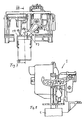
- the actuator 1 shown in Figure 1 has a Bearing 3 on, in a cistern only indicated here 2 is attached.
- the cistern 2 is preferably a Concealed cistern and the bearing block 3 is behind the here Not shown inspection opening arranged.
- For attachment of the Bearing 3 on cistern 2 has this laterally down projecting side supports 12 and 13.
- the bearing block 3 is preferably releasably attached to the cistern 2 and can at a revision be removed from the cistern.
- a rocker arm 7 is arranged, which is a horizontal Axis 8 is pivotable.
- a handlebar not shown here for manual operation hinged, which is movable in the direction of the arrow 10.
- an arm 26 of the rocker arm 7 in the direction of the arrow 11 is pivoted about the axis 8.
- the arm 26 engages in an opening 27 of a bracket 6 and raises in such Pivoting movement of the bracket 6 with a closure body attached thereto 5 on.
- the closure body 5 is part of one here not shown further outlet valve 4.
- the outlet valve. 4 can be designed as usual.
- the outlet valve 4 a float valve. There are also other outlet valves here conceivable.
- the bracket 6 has below the opening 27 a plate 17 with a horizontal surface 18. At the Plate 17 downwardly projecting holding means 19 are formed, which connect the bracket 6 with the closure body 5.
- a motor 15 On the bearing block 3 is a motor 15, in particular a servomotor attached, which has a one-armed pivot lever 16, the firmly seated on a motor shaft 22 and the according to Figure 2 with a hook-shaped front end 16a, the arm 26 loosely engages under.
- the motor 15 is housed in a housing 21 which attached to the bearing block 3, for example, is locked.
- a holder 14 is formed, which the housing 21st connects to the bearing block 3.
- the motor 15 is preferably provided with a not shown here Battery supplied.
- the switching on of the motor 15 takes place, for example on a key 24 shown in FIG. 10.
- This key 24 has in particular a proximity sensor 24a, with the the motor 15, for example, by a hand without contact can be.
- the button 24 can also be a mechanical Button. But there are other suitable means here as well for contactless remote triggering possible.
- the motor 15 according to Figure 10 has a known control 28. This is designed so that the pivot lever 16 when turning on the motor 15 an angular excursion ⁇ exerts.
- Position C is usually the resting position or basic position.
- the position D corresponds to the position in which the closure body 5 is completely raised and thus the outlet valve 4 is open.
- the positions B and A are further possible pivotal positions of the pivot lever 16.
- the position It corresponds to an upper reference point and the position A a lower reference point.
- the controller 28 is now designed to that the angular stroke of the pivot lever 16 at least at a first actuation automatically to the existing valve the closure body 5 adapts.
- H is a such existing valve lift indicated by H.
- the valve lift H is the maximum distance in which the valve body from the Lock position can be raised. Next up and even further down the closure body can not be moved become. This stroke H may vary due to manufacturing tolerances be.
- the end positions can be different be.
- the upper reference point is reached when the closure body 5 is completely raised.
- the lower reference point is then reached when the pivot lever 16 is present on the bearing block 3.
- the pivot lever 16 can then not continue counterclockwise be pivoted. Also in this position is a strong Current increase, by which the controller 28 the lower reference point recognizes.
- the motor 15 is preferably designed that the angular deviation ⁇ regardless of the direction of rotation of the Swing lever 16 is adjusted. Is the engine counterclockwise? Polarity, the controller recognizes this as the wrong direction of rotation and reverses the engine.
- Both reference points recognize the Control 28 due to a current increase.
- the two reference points are each stored by the controller 28.
- At a further actuation of the pivot lever 16 then leads this set and stored maximum angular stroke. This is then, for example, the angular deviation ⁇ shown in FIG. 10, which is for example 45 °.
- the originally possible angular stroke of for example 180 ° is thus restricted to 45 °.
- the circuit 28 is preferably set to periodically, For example, after 1'000 rinses the Winkelhub new adjusted. This is an adaptation to any changes the outlet valve 4 possible.
- the number of strokes, after which each the angular deviation ⁇ is readjusted, is preferably adjustable.
- the outlet valve 4 is closed.
- the swivel lever 16 is in the rest position and this corresponds in the figure 10 about the position C.
- the cistern 2 is filled with water and ready for a rinse. If the engine 15 by remote release or switched on by mechanical actuation of the key 24, Thus, the pivot lever 16 in Figure 1 in a clockwise direction pivoted. Since the pivot lever 16, the arm 26 according to FIG 2 engages, in this case the arm 16 in Figure 2 in a clockwise direction pivoted. The arm 26 takes in this case the bracket 6 and lifts this together with the closure body 5 vertically. Thereby the outlet valve 4 is opened and the flushing process initiated.
- the outlet valve 4 is a float valve, it remains the closure body 5 in the raised position in suspension, until essentially all rinse water has leaked out.
- the Figures 3 and 4 show the position of the pivot lever 16 at completely raised closure body 5. Before the closure body 5 closes the outlet valve 4, the pivots Pivot lever 16 back into the position shown in Figure 1 or in the position C. The closure body 5 is thus free and can after flushing back into the starting position shown in Figure 1 fall behind.
- the cistern 2 is now with a not shown here inlet valve filled again, after which the Cistern for another flushing is ready again.
- the pivot lever 16 can also be counterclockwise exercise an angular stroke. Again, the angular stroke automatically adapted to the existing valve lift H.
- the actuating device 1 is designed so that a Partial rinse is possible.
- a partial flush is a corresponding signal transmitted to the controller 28 or the Button 24 is equipped with a corresponding touchpad.
- the closure body 5 is thus raised the same as mentioned above.
- the closure body 5 also reaches the uppermost position shown in Figure 3 here.
- the pivot lever 16 is not here only until the rest position according to FIG 5, but time-controlled even further pivoted counterclockwise down. at this movement reaches the front hook-shaped end 16a of the Swing lever 16, the top 18 of the plate 17, as shown in FIG 7 is shown.
- the pivot lever 16 will now continue counterclockwise moved and the front end 16a loads with a Force according to arrow 29 on the plate 17 and on the closure body 5.
- the outlet valve 4 is thus closed prematurely.
- the flushing process is interrupted and only a part of the existing rinse water was used for rinsing. For example, these are 6 or 3 1 out of a total of for example, 9 1 rinse water.
- the flush volume of a partial flush can be adjusted continuously and is in particular by the Duration determined, after which the pivot lever 16 after the Trigger the partial flush again counterclockwise down pivots and thereby the closure body 5 in the closed position suppressed.
- the controller 28 is so set that either between a full flush and a Partial flush can be selected. After a partial rinse goes the Pivot lever 16 automatically in the rest position according to FIG. 1 back.
- the actuating device 1 can also be triggered mechanically.
- the rocker arm 7 at a pivoted not shown here actuator plate. Since the Swivel lever 16 engages under the arm 26, this can from the pivot lever 16 lifted and the closure body 5 are raised. After flushing the closure body 5 falls back into the in Figures 1 and 2 shown position. The pivot lever 16 remains in such a mechanical flushing in the in the figures 1 and 2 shown rest position, thus in the position C.
Landscapes
- Engineering & Computer Science (AREA)
- Aviation & Aerospace Engineering (AREA)
- Health & Medical Sciences (AREA)
- Life Sciences & Earth Sciences (AREA)
- Hydrology & Water Resources (AREA)
- Public Health (AREA)
- Water Supply & Treatment (AREA)
- Mechanically-Actuated Valves (AREA)
- Extrusion Moulding Of Plastics Or The Like (AREA)
- Endoscopes (AREA)
Claims (12)
- Dispositif d'actionnement pour une soupape de vidage (4) d'un dispositif de chasse, comportant un moteur (15), qui possède une unité de commande (28) et un levier pivotant (16), qui, pour le déclenchement d'une opération de chasse soulève, sur une course angulaire (α), un corps de fermeture (5) de la soupape de vidage (4), caractérisé en ce que le moteur (15) est commandé de telle sorte que la course angulaire (α) du levier pivotant (16) s'adapte automatiquement à une course existante (H) de la soupape par le fait que l'unité de commande peut reconnaítre et mémorise les positions d'extrémité (C, D) du levier pivotant (16), qui sont définies par la course maximale (H) de la soupape.
- Dispositif selon la revendication 1,
caractérisé en ce que lors d'un premier soulèvement et d'une première fermeture du corps de fermeture (5), le moteur (15) détermine la course angulaire (α) maximale possible et la mémorise dans une unité de commande (28). - Dispositif selon la revendication 1 ou 2, caractérisé en ce qu'en raison d'un accroissement respectif du courant, le moteur (15) identifie un point de référence supérieur et un point de référence inférieur (C, D) et mémorise ces réglables angulaires ou points de référence.
- Dispositif selon l'une des revendications 1 à 3, caractérisé en ce que lors du déclenchement d'une chasse complète, le moteur (15) exécute une course angulaire (α) jusqu'au-dessous du point de référence inférieur (D).
- Dispositif selon l'une des revendications 1 à 3, caractérisé en ce que pour le déclenchement d'une chasse partielle, le moteur (15) repousse, à l'aide du levier pivotant (16), le corps de fermeture (5) jusqu'au-dessous du point de référence inférieur (C) et ferme de façon précoce la soupape de vidage (4).
- Dispositif selon l'une des revendications 1 à 5, caractérisé en ce que le moteur (15) réalise automatiquement l'ajustement complémentaire de la course angulaire (α) après un nombre pouvant être prédéterminé de courses à l'aide d'une opération de chasse de référence.
- Dispositif selon l'une des revendications 1 à 6, caractérisé en ce que le moteur (15) règle la course angulaire (α) indépendamment du sens de rotation du levier pivotant (16).
- Dispositif selon l'une des revendications 1 à 7, caractérisé en ce que le moteur (15) est monté dans un bloc formant palier (3).
- Dispositif selon la revendication 8, caractérisé en ce que sur le bloc formant palier (3) est monté de façon à pouvoir pivoter, et ce à distance du moteur (15), un levier basculant (7) qui s'engage dans un étrier (6) du corps de fermeture (5) et est amené à pivoter vers le haut lors du déclenchement d'une opération de chasse par le levier pivotant (16).
- Dispositif selon l'une des revendications 1 à 9, caractérisé en ce que le corps de fermeture (5) comporte au niveau de son extrémité supérieure, une face supérieure (18), avec laquelle le levier pivotant (16) coopère dans le cas d'une opération de chasse partielle pour la fermeture avancée de la soupape de vidage (4).
- Dispositif selon la revendication 10, caractérisé en ce que le cas d'une opération de chasse partielle, le levier pivotant (16) appuie à partir du haut sur la face supérieure (18) pour réaliser une fermeture avancée de la soupape de vidage (4).
- Dispositif selon l'une des revendications 1 à 11, caractérisé en ce que le moteur (15) est un servomoteur.
Priority Applications (3)
| Application Number | Priority Date | Filing Date | Title |
|---|---|---|---|
| EP02405692A EP1389657B1 (fr) | 2002-08-14 | 2002-08-14 | Dispositif de commande pour un clapet d'évacuation d'une chasse d'eau |
| DE50204092T DE50204092D1 (de) | 2002-08-14 | 2002-08-14 | Betätigungsvorrichtung für ein Auslaufventil einer Spülvorrichtung |
| AT02405692T ATE303475T1 (de) | 2002-08-14 | 2002-08-14 | Betätigungsvorrichtung für ein auslaufventil einer spülvorrichtung |
Applications Claiming Priority (1)
| Application Number | Priority Date | Filing Date | Title |
|---|---|---|---|
| EP02405692A EP1389657B1 (fr) | 2002-08-14 | 2002-08-14 | Dispositif de commande pour un clapet d'évacuation d'une chasse d'eau |
Publications (2)
| Publication Number | Publication Date |
|---|---|
| EP1389657A1 EP1389657A1 (fr) | 2004-02-18 |
| EP1389657B1 true EP1389657B1 (fr) | 2005-08-31 |
Family
ID=30470352
Family Applications (1)
| Application Number | Title | Priority Date | Filing Date |
|---|---|---|---|
| EP02405692A Expired - Lifetime EP1389657B1 (fr) | 2002-08-14 | 2002-08-14 | Dispositif de commande pour un clapet d'évacuation d'une chasse d'eau |
Country Status (3)
| Country | Link |
|---|---|
| EP (1) | EP1389657B1 (fr) |
| AT (1) | ATE303475T1 (fr) |
| DE (1) | DE50204092D1 (fr) |
Family Cites Families (3)
| Publication number | Priority date | Publication date | Assignee | Title |
|---|---|---|---|---|
| GB2263916B (en) * | 1992-01-22 | 1995-06-28 | Kohler Co | Seat cover actuated flushing mechanism for toilet |
| US5307524A (en) * | 1992-03-25 | 1994-05-03 | Veal Bennie N | Automatic toilet seat device |
| DE10009253A1 (de) * | 2000-02-28 | 2001-08-30 | Aquis Sanitaer Ag Rebstein | Spülvorrichtung für Toiletten |
-
2002
- 2002-08-14 AT AT02405692T patent/ATE303475T1/de active
- 2002-08-14 EP EP02405692A patent/EP1389657B1/fr not_active Expired - Lifetime
- 2002-08-14 DE DE50204092T patent/DE50204092D1/de not_active Expired - Lifetime
Also Published As
| Publication number | Publication date |
|---|---|
| DE50204092D1 (de) | 2005-10-06 |
| EP1389657A1 (fr) | 2004-02-18 |
| ATE303475T1 (de) | 2005-09-15 |
Similar Documents
| Publication | Publication Date | Title |
|---|---|---|
| DE69311608T2 (de) | Spülkastenanlage | |
| EP0722020B1 (fr) | Dispositif de chasse dans un réservoir de chasse d'eau | |
| DE4241023C2 (de) | Vorrichtung zur Verhinderung oder Verminderung der durch Waschbecken, Spülbecken, Badewannen o. dgl. verursachten Keime | |
| CH659100A5 (de) | Betaetigungsvorrichtung eines ablaufventils eines spuelkastens. | |
| EP1964988B1 (fr) | Dispositif de chasse d'eau électromécanique | |
| EP1703027B1 (fr) | Dispositif pour activer le clapet d'écoulement d'articles sanitaires et en particulier une baignoire | |
| EP1156166A2 (fr) | Réservoir de chasse pour toilettes et méthode pour actionner un tel réservoir | |
| DE3618671C2 (fr) | ||
| EP1389657B1 (fr) | Dispositif de commande pour un clapet d'évacuation d'une chasse d'eau | |
| DE60224483T2 (de) | Schwenktüre für Kraftfahrzeuge | |
| WO2005005757A1 (fr) | Serrure de portiere de vehicule automobile | |
| DE2556520A1 (de) | Verriegelungsvorrichtung an der tuer einer geschirrspuelmaschine | |
| EP1135559B1 (fr) | Dispositif d'actionnement de chasse d'eau sans contact pour des toilettes | |
| EP1672130B1 (fr) | Soupape d'évacuation d'un réservoir de chasse | |
| EP1614840B1 (fr) | Fermeture assistée pour un volet ou une porte de véhicule | |
| DE19811920C2 (de) | Regenwasser-Versorgungsvorrichtung | |
| DE102004029186B4 (de) | Vorrichtung zum kontrollierten Öffnen und Schließen eines mit einem Toilettenbecken im Bereich einer Lagerung gelenkig verbundenen Toilettendeckels | |
| EP1460188B1 (fr) | Dispositif de chasse pour un réservoir de chasse d'eau | |
| EP1795662B1 (fr) | Dispositif pour activer le clapet d'un réservoir de chasse d'eau | |
| DE3640216A1 (de) | Klosettspuelkasten | |
| EP2072696B1 (fr) | Dispositif d'actionnement pour chasse d'eau | |
| EP1421246A1 (fr) | Fermeture de portiere de vehicule automobile | |
| EP0652329B1 (fr) | Dispositif de déclenchement et d'arrêt pour une soupape de vidange d'un réservoir de chasse d'eau | |
| EP1270829B1 (fr) | Dispositif pour l'actionnement d'une soupape de vidange d'un réservoir de chasse d'eau | |
| EP1010826A1 (fr) | Dispositif d'écoulement pour chasse d'eau |
Legal Events
| Date | Code | Title | Description |
|---|---|---|---|
| PUAI | Public reference made under article 153(3) epc to a published international application that has entered the european phase |
Free format text: ORIGINAL CODE: 0009012 |
|
| AK | Designated contracting states |
Kind code of ref document: A1 Designated state(s): AT BE BG CH CY CZ DE DK EE ES FI FR GB GR IE IT LI LU MC NL PT SE SK TR |
|
| AX | Request for extension of the european patent |
Extension state: AL LT LV MK RO SI |
|
| 17P | Request for examination filed |
Effective date: 20040319 |
|
| 17Q | First examination report despatched |
Effective date: 20040809 |
|
| AKX | Designation fees paid |
Designated state(s): AT BE BG CH CY CZ DE DK EE ES FI FR GB GR IE IT LI LU MC NL PT SE SK TR |
|
| GRAP | Despatch of communication of intention to grant a patent |
Free format text: ORIGINAL CODE: EPIDOSNIGR1 |
|
| GRAS | Grant fee paid |
Free format text: ORIGINAL CODE: EPIDOSNIGR3 |
|
| GRAA | (expected) grant |
Free format text: ORIGINAL CODE: 0009210 |
|
| AK | Designated contracting states |
Kind code of ref document: B1 Designated state(s): AT BE BG CH CY CZ DE DK EE ES FI FR GB GR IE IT LI LU MC NL PT SE SK TR |
|
| PG25 | Lapsed in a contracting state [announced via postgrant information from national office to epo] |
Ref country code: IT Free format text: LAPSE BECAUSE OF NON-PAYMENT OF DUE FEES Effective date: 20050831 Ref country code: IE Free format text: LAPSE BECAUSE OF FAILURE TO SUBMIT A TRANSLATION OF THE DESCRIPTION OR TO PAY THE FEE WITHIN THE PRESCRIBED TIME-LIMIT Effective date: 20050831 Ref country code: FI Free format text: LAPSE BECAUSE OF FAILURE TO SUBMIT A TRANSLATION OF THE DESCRIPTION OR TO PAY THE FEE WITHIN THE PRESCRIBED TIME-LIMIT Effective date: 20050831 Ref country code: SK Free format text: LAPSE BECAUSE OF FAILURE TO SUBMIT A TRANSLATION OF THE DESCRIPTION OR TO PAY THE FEE WITHIN THE PRESCRIBED TIME-LIMIT Effective date: 20050831 Ref country code: CZ Free format text: LAPSE BECAUSE OF FAILURE TO SUBMIT A TRANSLATION OF THE DESCRIPTION OR TO PAY THE FEE WITHIN THE PRESCRIBED TIME-LIMIT Effective date: 20050831 |
|
| REG | Reference to a national code |
Ref country code: CH Ref legal event code: EP Ref country code: GB Ref legal event code: FG4D Free format text: NOT ENGLISH |
|
| REG | Reference to a national code |
Ref country code: IE Ref legal event code: FG4D Free format text: LANGUAGE OF EP DOCUMENT: GERMAN |
|
| REF | Corresponds to: |
Ref document number: 50204092 Country of ref document: DE Date of ref document: 20051006 Kind code of ref document: P |
|
| REG | Reference to a national code |
Ref country code: CH Ref legal event code: NV Representative=s name: ISLER & PEDRAZZINI AG |
|
| PG25 | Lapsed in a contracting state [announced via postgrant information from national office to epo] |
Ref country code: BG Free format text: LAPSE BECAUSE OF FAILURE TO SUBMIT A TRANSLATION OF THE DESCRIPTION OR TO PAY THE FEE WITHIN THE PRESCRIBED TIME-LIMIT Effective date: 20051130 Ref country code: GR Free format text: LAPSE BECAUSE OF FAILURE TO SUBMIT A TRANSLATION OF THE DESCRIPTION OR TO PAY THE FEE WITHIN THE PRESCRIBED TIME-LIMIT Effective date: 20051130 Ref country code: SE Free format text: LAPSE BECAUSE OF FAILURE TO SUBMIT A TRANSLATION OF THE DESCRIPTION OR TO PAY THE FEE WITHIN THE PRESCRIBED TIME-LIMIT Effective date: 20051130 Ref country code: DK Free format text: LAPSE BECAUSE OF FAILURE TO SUBMIT A TRANSLATION OF THE DESCRIPTION OR TO PAY THE FEE WITHIN THE PRESCRIBED TIME-LIMIT Effective date: 20051130 |
|
| PG25 | Lapsed in a contracting state [announced via postgrant information from national office to epo] |
Ref country code: ES Free format text: LAPSE BECAUSE OF FAILURE TO SUBMIT A TRANSLATION OF THE DESCRIPTION OR TO PAY THE FEE WITHIN THE PRESCRIBED TIME-LIMIT Effective date: 20051212 |
|
| GBT | Gb: translation of ep patent filed (gb section 77(6)(a)/1977) | ||
| PG25 | Lapsed in a contracting state [announced via postgrant information from national office to epo] |
Ref country code: PT Free format text: LAPSE BECAUSE OF FAILURE TO SUBMIT A TRANSLATION OF THE DESCRIPTION OR TO PAY THE FEE WITHIN THE PRESCRIBED TIME-LIMIT Effective date: 20060223 |
|
| REG | Reference to a national code |
Ref country code: IE Ref legal event code: FD4D |
|
| ET | Fr: translation filed | ||
| PLBE | No opposition filed within time limit |
Free format text: ORIGINAL CODE: 0009261 |
|
| STAA | Information on the status of an ep patent application or granted ep patent |
Free format text: STATUS: NO OPPOSITION FILED WITHIN TIME LIMIT |
|
| 26N | No opposition filed |
Effective date: 20060601 |
|
| PG25 | Lapsed in a contracting state [announced via postgrant information from national office to epo] |
Ref country code: MC Free format text: LAPSE BECAUSE OF NON-PAYMENT OF DUE FEES Effective date: 20060831 |
|
| REG | Reference to a national code |
Ref country code: CH Ref legal event code: PCAR Free format text: ISLER & PEDRAZZINI AG;POSTFACH 1772;8027 ZUERICH (CH) |
|
| PG25 | Lapsed in a contracting state [announced via postgrant information from national office to epo] |
Ref country code: EE Free format text: LAPSE BECAUSE OF FAILURE TO SUBMIT A TRANSLATION OF THE DESCRIPTION OR TO PAY THE FEE WITHIN THE PRESCRIBED TIME-LIMIT Effective date: 20050831 |
|
| PG25 | Lapsed in a contracting state [announced via postgrant information from national office to epo] |
Ref country code: TR Free format text: LAPSE BECAUSE OF FAILURE TO SUBMIT A TRANSLATION OF THE DESCRIPTION OR TO PAY THE FEE WITHIN THE PRESCRIBED TIME-LIMIT Effective date: 20050831 Ref country code: LU Free format text: LAPSE BECAUSE OF NON-PAYMENT OF DUE FEES Effective date: 20060814 |
|
| PG25 | Lapsed in a contracting state [announced via postgrant information from national office to epo] |
Ref country code: CY Free format text: LAPSE BECAUSE OF FAILURE TO SUBMIT A TRANSLATION OF THE DESCRIPTION OR TO PAY THE FEE WITHIN THE PRESCRIBED TIME-LIMIT Effective date: 20050831 |
|
| REG | Reference to a national code |
Ref country code: GB Ref legal event code: 732E Free format text: REGISTERED BETWEEN 20100121 AND 20100127 |
|
| REG | Reference to a national code |
Ref country code: CH Ref legal event code: PUE Owner name: GEBERIT INTERNATIONAL AG Free format text: GEBERIT TECHNIK AG#SCHACHENSTRASSE 77#8645 JONA (CH) -TRANSFER TO- GEBERIT INTERNATIONAL AG#SCHACHENSTRASSE 77#8645 JONA (CH) |
|
| REG | Reference to a national code |
Ref country code: NL Ref legal event code: SD Effective date: 20100304 |
|
| PGRI | Patent reinstated in contracting state [announced from national office to epo] |
Ref country code: IT Effective date: 20091201 |
|
| REG | Reference to a national code |
Ref country code: FR Ref legal event code: TP |
|
| PGFP | Annual fee paid to national office [announced via postgrant information from national office to epo] |
Ref country code: FR Payment date: 20120906 Year of fee payment: 11 |
|
| REG | Reference to a national code |
Ref country code: DE Ref legal event code: R082 Ref document number: 50204092 Country of ref document: DE Representative=s name: HOEGER, STELLRECHT & PARTNER PATENTANWAELTE, DE Ref country code: DE Ref legal event code: R082 Ref document number: 50204092 Country of ref document: DE Representative=s name: HOEGER, STELLRECHT & PARTNER PATENTANWAELTE MB, DE |
|
| REG | Reference to a national code |
Ref country code: FR Ref legal event code: ST Effective date: 20140430 |
|
| PG25 | Lapsed in a contracting state [announced via postgrant information from national office to epo] |
Ref country code: FR Free format text: LAPSE BECAUSE OF NON-PAYMENT OF DUE FEES Effective date: 20130902 |
|
| PGFP | Annual fee paid to national office [announced via postgrant information from national office to epo] |
Ref country code: NL Payment date: 20140820 Year of fee payment: 13 |
|
| PGFP | Annual fee paid to national office [announced via postgrant information from national office to epo] |
Ref country code: GB Payment date: 20140820 Year of fee payment: 13 |
|
| PGFP | Annual fee paid to national office [announced via postgrant information from national office to epo] |
Ref country code: IT Payment date: 20140826 Year of fee payment: 13 |
|
| PGFP | Annual fee paid to national office [announced via postgrant information from national office to epo] |
Ref country code: BE Payment date: 20140820 Year of fee payment: 13 |
|
| REG | Reference to a national code |
Ref country code: DE Ref legal event code: R082 Ref document number: 50204092 Country of ref document: DE Representative=s name: HOEGER, STELLRECHT & PARTNER PATENTANWAELTE MB, DE |
|
| PGFP | Annual fee paid to national office [announced via postgrant information from national office to epo] |
Ref country code: CH Payment date: 20150811 Year of fee payment: 14 |
|
| PGFP | Annual fee paid to national office [announced via postgrant information from national office to epo] |
Ref country code: AT Payment date: 20150820 Year of fee payment: 14 |
|
| GBPC | Gb: european patent ceased through non-payment of renewal fee |
Effective date: 20150814 |
|
| PG25 | Lapsed in a contracting state [announced via postgrant information from national office to epo] |
Ref country code: IT Free format text: LAPSE BECAUSE OF NON-PAYMENT OF DUE FEES Effective date: 20150814 |
|
| REG | Reference to a national code |
Ref country code: NL Ref legal event code: MM Effective date: 20150901 |
|
| PG25 | Lapsed in a contracting state [announced via postgrant information from national office to epo] |
Ref country code: NL Free format text: LAPSE BECAUSE OF NON-PAYMENT OF DUE FEES Effective date: 20150901 |
|
| PG25 | Lapsed in a contracting state [announced via postgrant information from national office to epo] |
Ref country code: GB Free format text: LAPSE BECAUSE OF NON-PAYMENT OF DUE FEES Effective date: 20150814 |
|
| REG | Reference to a national code |
Ref country code: CH Ref legal event code: PL |
|
| REG | Reference to a national code |
Ref country code: AT Ref legal event code: MM01 Ref document number: 303475 Country of ref document: AT Kind code of ref document: T Effective date: 20160814 |
|
| PG25 | Lapsed in a contracting state [announced via postgrant information from national office to epo] |
Ref country code: CH Free format text: LAPSE BECAUSE OF NON-PAYMENT OF DUE FEES Effective date: 20160831 Ref country code: LI Free format text: LAPSE BECAUSE OF NON-PAYMENT OF DUE FEES Effective date: 20160831 |
|
| PG25 | Lapsed in a contracting state [announced via postgrant information from national office to epo] |
Ref country code: AT Free format text: LAPSE BECAUSE OF NON-PAYMENT OF DUE FEES Effective date: 20160814 |
|
| PG25 | Lapsed in a contracting state [announced via postgrant information from national office to epo] |
Ref country code: BE Free format text: LAPSE BECAUSE OF NON-PAYMENT OF DUE FEES Effective date: 20150831 |
|
| PGFP | Annual fee paid to national office [announced via postgrant information from national office to epo] |
Ref country code: DE Payment date: 20170822 Year of fee payment: 16 |
|
| REG | Reference to a national code |
Ref country code: DE Ref legal event code: R119 Ref document number: 50204092 Country of ref document: DE |
|
| PG25 | Lapsed in a contracting state [announced via postgrant information from national office to epo] |
Ref country code: DE Free format text: LAPSE BECAUSE OF NON-PAYMENT OF DUE FEES Effective date: 20190301 |