EP1389737B1 - Weitwinkelsucher mit schaltbarem Mikroblendenraster - Google Patents
Weitwinkelsucher mit schaltbarem Mikroblendenraster Download PDFInfo
- Publication number
- EP1389737B1 EP1389737B1 EP20030008679 EP03008679A EP1389737B1 EP 1389737 B1 EP1389737 B1 EP 1389737B1 EP 20030008679 EP20030008679 EP 20030008679 EP 03008679 A EP03008679 A EP 03008679A EP 1389737 B1 EP1389737 B1 EP 1389737B1
- Authority
- EP
- European Patent Office
- Prior art keywords
- intermediate image
- shutter array
- detector
- optical system
- imaging optical
- Prior art date
- Legal status (The legal status is an assumption and is not a legal conclusion. Google has not performed a legal analysis and makes no representation as to the accuracy of the status listed.)
- Expired - Lifetime
Links
- 230000003287 optical effect Effects 0.000 claims description 47
- 238000003384 imaging method Methods 0.000 claims description 35
- 239000007787 solid Substances 0.000 claims description 8
- 230000000873 masking effect Effects 0.000 claims 1
- 230000000007 visual effect Effects 0.000 description 12
- 230000005855 radiation Effects 0.000 description 3
- 239000011159 matrix material Substances 0.000 description 2
- 241000251468 Actinopterygii Species 0.000 description 1
- 229910000831 Steel Inorganic materials 0.000 description 1
- 230000001419 dependent effect Effects 0.000 description 1
- 238000006073 displacement reaction Methods 0.000 description 1
- 238000004519 manufacturing process Methods 0.000 description 1
- 238000013507 mapping Methods 0.000 description 1
- 230000000737 periodic effect Effects 0.000 description 1
- 210000001747 pupil Anatomy 0.000 description 1
- 238000005070 sampling Methods 0.000 description 1
- 239000010959 steel Substances 0.000 description 1
- 239000000758 substrate Substances 0.000 description 1
Images


Classifications
-
- G—PHYSICS
- G02—OPTICS
- G02B—OPTICAL ELEMENTS, SYSTEMS OR APPARATUS
- G02B13/00—Optical objectives specially designed for the purposes specified below
- G02B13/06—Panoramic objectives; So-called "sky lenses" including panoramic objectives having reflecting surfaces
-
- G—PHYSICS
- G02—OPTICS
- G02B—OPTICAL ELEMENTS, SYSTEMS OR APPARATUS
- G02B26/00—Optical devices or arrangements for the control of light using movable or deformable optical elements
- G02B26/02—Optical devices or arrangements for the control of light using movable or deformable optical elements for controlling the intensity of light
Definitions
- the invention relates to an all-around seeker device for observing a large solid angle by means of an image-resolving detector with a grid of detector elements, comprising: a first imaging optical system through which an intermediate image of a field of view can be generated in an intermediate image plane, a second imaging optical system, through which the intermediate image plane is imaged on the image-resolving detector, wherein each detector element is associated with an intermediate image area, which is imaged onto the detector element, and arranged in the intermediate image plane micro-aperture arrangement, which successively different partial areas of each intermediate image area can be released under cover of the remaining intermediate image area.
- Rotary seekers have the task of a large solid angle, such as a half-space, by means of a responsive to radiation from the solid angle detector to observe.
- Known all-round search devices operate with a periodic sampling of the Solid angle by means of movable optical members, through which a Ab Struktursstrahlengang is distractable. Examples of such rotary seekers show the US 5,977,536 A and EP 0 840 157 A2. Such Rundumsuch mar are consuming, bulky and prone to failure by moving parts.
- the US 6,005,721 A (DE 199 04 914 A1) shows a viewfinder for detecting a large visual field.
- the viewfinder contains as the first imaging optical system one imaging lens and arranged in front of the pupil flat, four-sided Pyramid as beam-deflecting optics. This will be in the intermediate image plane superimposed pictures of four different visual field areas, wherein the Imaging beam paths for the different visual field areas different directions on the intermediate image level.
- a micro-optical Strahlablenkelement which the different imaging beam paths successively in the beam path of the second imaging optical system and thus the image-resolving detector passes.
- the detector therefore receives successively images of various macroscopic ones Field of view, which becomes an "electronic image" of a large visual field be assembled.
- the opening angle of the first imaging optical limited Systems the size of the field of view at once detectable.
- the detector determines the image resolution.
- the micro lens system switches between different ones Observation directions around.
- the entire detectable field of vision is opposite the opening angle of the first imaging optical system by a factor of four enlarged but limited.
- Such an arrangement can not be considered a round-finder be used to detect a half-space.
- an image-resolving detector arrangement in which by a first imaging optical system, an image of an object scene in an intermediate image plane is generated. This picture is taken by means of a second imaging optical system on an image-resolving detector with a raster imaged by detector elements.
- This intermediate image plane Lens grid There are two in this intermediate image plane Lens grid: A first lenticular grid of diverging lenses is dimensioned so that each detector element is associated with four diverging lenses of the first lens raster. These four diverging lenses and only these are from the second optical system imaged on the detector element. They define a the detector element assigned intermediate image area.
- the second, object-side lenticular contains for every intermediate image area only one condenser lens. The space between them Bulk lenses is opaque.
- the second lenticular grid can now be controlled by a piezo actuator moved gradually in four different positions relative to the first lenticular grid become. Each of these four positions is part of the area of each detector element assigned. Only this part is exposed in the relevant position. That brings one Increasing the resolution, because in every position a signal of the detector element after Made according to a pixel corresponding to only one quarter of the intermediate image area becomes. The signals can then be nested into an electronic image be, which has a relation to the resolution of the detector increased resolution.
- the two lens grids can be superimposed on a further relative displacement, by which in a similar arrangement as that of US 60 05 721 A the Image beam paths of different superimposed images in the intermediate image plane various visual field areas are successively passed to the detector.
- a large field of view is in the detector arrangement according to DE 199 04 914 A1 as in US 60 05 721 A by superimposing images of the visual field areas in the Intermediate image plane and deflection of the imaging beam paths by lenticular screen, thus breaking limbs, reached.
- the thereby detectable field of view is like the Detector arrangement according to US 60 05 721 A limited.
- the lenticular two Perform adjusting movements with high precision. That's hard to do. The production of precise lenticular grids is expensive.
- US 519 203 A relates to a searcher for target-tracking missiles.
- a first Imaging optical system produces an image of a field of view on one Mirror grid, which consists of a variety of individually controllable, tiltable Mirror elements exists.
- This mirror grid is represented by a second image Optical system imaged on an image-resolving detector, the one has two-dimensional arrangement of detector elements.
- Each detector element is assigned a sub-matrix of the mirror grid, which has a plurality of mirror elements and is imaged onto the detector element. To increase the resolution will successively each one mirror element of each sub-matrix so controlled that it reflect imaging rays incident on the associated detector element.
- EP 1 026 875 A2 shows in FIG. 1 a micro-aperture grid for increasing the resolution.
- This Miltroblendenraster is located immediately in front of a substrate that is on his Front forms a microlens grid and on its back the detector elements an image-resolving detector carries.
- EP 1 026 875 A2 an arrangement is described, in which for detecting a large field of view in the image plane several visual field parts are superimposed and on the beam direction of the imaging beams be passed in succession to the second optics and the image-resolving detector.
- DE 43 27 944 A1 shows a diaphragm grid for improving the resolution of Image detectors in microscopes.
- EP 0 432 025 A1 relates to a receiver for modulated optical signals for Transmitting messages from an aircraft carrier to an aircraft.
- the problem is there, these optical signals, from whatever direction they come, like
- the position and attitude of the aircraft to the aircraft carrier is also on one Lead detector array. That's why those sent by the sender, modulated optical signals detected by a fish-eye optics.
- GB 2 368 221 A shows a camera apparatus which, in a conventional as well as in an omnidirectional mode.
- the omnidirectional Illustration is made possible via a fish-eye optics.
- the invention is based on the object, a detector arrangement of the above so-called type so that it can be used as Rundumsuchêt.
- the invention is further based on the object, such a detector arrangement so build up that they capture a very large solid angle with high resolution can. In this case, a high accuracy of the generated "electronic image" to be guaranteed.
- the invention is finally based on the object, a detector arrangement for Capture very large solid angles, especially a half-space, with as possible simple means and avoiding wear-prone, microscopic mobile Building parts.
- the invention uses a "fish-eye optic" as the first imaging optical system.
- fish eye optics are known per se. It is about Wide-angle lenses, which, like a fisheye, have an extremely large solid angle, to the half-space, able to capture. That way, the whole Half space at once pictured as a picture in the intermediate image plane. It takes place so in the intermediate image plane no superposition of visual field areas such as in the known detector arrangements described above. It has shown, that nevertheless the resolution of the intermediate image is greater than the resolution of the detector. Therefore, in the intermediate image plane is a micro-aperture arrangement arranged, which successively different to increase the resolution Subareas of each interim image area assigned to a detector element releases.
- this micro-aperture arrangement is a pure aperture pattern executed without breaking optical links. This results in a "staring" Around seeker device.
- the only movements are the microscopic movements in the micro-aperture arrangement. It has been shown that these movements with high precision can be generated. It is not necessary to have additional visual field areas subsequently to assemble into an electronic picture.
- Embodiments of the invention are the subject of the dependent claims.
- Fig. 1 is generally 10 with a first imaging optical system in the form of a Fisheye lens, which is a field of view encompassing the half-space imaged on an intermediate image plane 12.
- the fisheye lens 10 has a object-side strong negative, convex-concave lens 14 on.
- the radius of curvature of Image-side surface of the lens 14 is substantially smaller than the radius of curvature of object-side surface.
- the lens 14 is therefore relatively thin in the middle.
- the thickness of the Lens 14 increases sharply towards the edge. Looking at them at different intervals from the optical axis 16 lying portions of the lens 14 as "prisms", then the further the angle between the refracting surfaces of these prisms you move away from the optical axis. The greater the distraction of the Rays.
- the rays, with the optical axis 16 form a large angle, as strongly broken by prisms, so that they then under a much smaller angle with the optical axis on the image side Lens system with the lenses 18, 20 and 22 fall.
- This lens system only needs to have a relatively small opening angle.
- the along the optical axis 16 incident parallel light beam 24 is through the negative lens 14 made divergent. This divergent light beam is then through the Lenses 18, 20 and 22 at a point 26 in the intermediate image plane 12 and on the optical axis 16 collected.
- the object-side lens 14 also detects light rays that under a Angle of 90 ° to the optical axis 16 occur.
- Such an incidental parallel Light beam is designated in Fig. 1 at 28.
- This light beam 28 is through the outer edge of the lens 14 with a "prism" whose entrance and exit surfaces a form large angles with each other, strongly distracted and also made divergent.
- This divergent light beam is incident at a relatively small angle to the optical axis on the rest of the lens system with the lenses 18, 20 and 22 and is in the Intermediate image plane collected in a pixel 30.
- a third parallel light beam 32 is incident from a direction that is a little smaller angle with the optical axis 16 forms. That of the lens 14 for this Light beam formed "prism" has a smaller angle between its surfaces and deflects the light beam accordingly by a smaller angle than the, to the the light beam 28 is deflected.
- the divergent made by the lens 14 Light beam 32 falls at a smaller angle to the optical axis than that Light beam 28 on the lenses 18, 20 and 22 formed by the lens system and is from this in a pixel 34 radially inwardly of the pixel 30 in the Image plane 12 collected.
- the light beams 24, 28 and 32 are bounded by a behind the lens 22nd arranged aperture diaphragm 36.
- the described fisheye lens thus forms the entire half-space of 180 °, i.e. from + 90 ° to -90 ° with respect to the optical axis 16 in an image in the Intermediate image plane 12 from.
- the picture is usually something distorted: a straight line not passing through the optical axis 16 appears curved.
- FIG. 2 shows a second imaging optical system, indicated generally at 38.
- the second imaging optical system is in the Engelgrueben 12th generated image of the visual field, i. of the half-space, on an image-resolving Detector 40 shown.
- This image is taken in a telecentric beam path.
- the aperture stop of the system 38 pictured backwards in the infinite. This means that all the rays that come through a Point of the aperture stop go, object-side form a parallel beam.
- the axial position of a in an image plane, here the intermediate image plane 12th seated visual field iris uncritical for the brightness of the pixels.
- a lens 42 arranged on the image side forms an aperture stop of the second lens imaging optical system. 2 shows two beams 44 and 46, which by the intermediate image generated in the intermediate image plane 12 and by the Edge of the lens 42 go.
- Fig. 2 does not show the imaging rays of the image of the intermediate image on the detector 40. It can be seen that all are separated by an edge point of the Lens 42 finally form "backwards" a parallel beam.
- the intermediate image in the intermediate image plane 12 is in a conventional manner by the of five lenses, namely the lenses 48, 50, 52, 54 and the lens 42 existing second imaging optical system or lens 38 imaged on the detector 40.
- the Image is reduced in size with a reduction of 2: 1. This will be the Dimensions of the intermediate image reduced to the dimensions of the detector.
- the Detector 40 is an image-resolving detector with a grid or mosaic of Detector elements.
- Each detector element is now associated with an intermediate image area, which passes through the second imaging optical system is imaged on this detector element.
- a square detector element is a corresponding square area of the Intermediate image. If you imagine that the detector element is lit, then Through the system 38 "backwards" would be the associated intermediate image area illuminated. This one would turn backwards over the fisheye lens illuminate the corresponding area of the half-space. Since the fisheye lens the entire half-space in the intermediate image depicts, the resolution of such a built around round finder insufficient.
- the micro-aperture array can be a single square-micron grid Rasterberichte, each grid area having the dimensions of the has the above-explained intermediate image area.
- Each grid area has four same quadrant on.
- a quadrant is in uniform pattern for those of the detector detected radiation permeable, the other three quadrants are impermeable.
- This micro-aperture grid in two to each other vertical directions each one of the edge length of the quadrant corresponding step adjustable.
- the permeable quadrant now leaves only the Radiation to the detector 40, which falls on this quadrant.
- the remaining part of the Intermediate image area is covered in each case.
- the permeable quadrant forms an in the intermediate image plane 12 arranged visual field diaphragm.
- each intermediate image area can be scanned in quadrants.
- the signals of the detector elements obtained at each position of the micro-aperture grid are "nested” into an "electronic image” with increased resolution.
- FIGS to 5 A particularly advantageous embodiment of the micro-aperture arrangement is shown in FIGS to 5 shown.
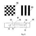
- the micro-diaphragm arrangement 56 consists of two superimposed micro-aperture grids 58 (FIG. 3) and 60 (FIG. 4).
- the micro-aperture grid 58 is a checkerboard pattern. Four contiguous fields of the checkerboard pattern have the dimensions of one of the square intermediate image areas. The checkerboard pattern is also arranged in each position so that each intermediate image area is covered by exactly four fields of the checkerboard pattern.
- the micro-aperture grid 60 is a stripe pattern with alternating transmissive and impermeable stripes 62 and 64, respectively. The width of each stripe 62 or 64 corresponds to the width of one field of the checkerboard pattern 58.
- the micro-aperture grid 60 overlies the micro-aperture grid 58 in any position such that each stripe 62 or 64 of the stripe pattern covers a vertical column in Figure 3 of the alternately transmissive and opaque fields of the checkerboard pattern.
- Fig.3 left column of the checkerboard pattern of the micro-aperture grid 58 is a translucent strip 62. So here is the checkerboard pattern, i. from top to bottom "bright, dark, light, dark, light dark”.
- the second column is due the impermeable strip 64 as a whole impermeable.
- FIG.3 and 5 top left shown by dashed lines and designated 66. It can be seen that the left in Fig.5 upper quadrant of belonging to this intermediate image area 66 micro-aperture is permeable and the other three quadrants are covered.
- microlens grid 58 is displaced in this position of the microlens grid 60 by one step, which corresponds to the height of a chessboard field, up in 3, then the right upper quadrant of the considered intermediate image area 66 released while the remaining quadrants are covered again.
- the adjustment of the two micro aperture can be done by means of piezo actuators.
- the two mutually adjustable micro aperture are slightly axial, ie in Direction of the optical axis 16, offset from each other. They are not both in exactly the intermediate image plane 12. By the telecentric beam path of the second but this is not critical to the imaging optical system.
Landscapes
- Physics & Mathematics (AREA)
- General Physics & Mathematics (AREA)
- Optics & Photonics (AREA)
- Transforming Light Signals Into Electric Signals (AREA)
Description
- Fig.1
- zeigt ein "Fischaugenobjektiv" als erstes abbildendes optisches System zur Erzeugung eines Bildes eines Halbraumes in einer Zwischenbildebene mit den Abbildungsstrahlen für verschiedene Einfallswinkel.
- Fig.2
- zeigt ein zweites abbildendes optisches System zum Abbbilden der in der Zwischenbildebene erzeugten Zwischenabbildung des Halbraumes auf einem bildauflösenden Detektor.
- Fig.3
- zeigt ein erstes Blendenraster mit einem Schachbrettmuster einer in der Zwischenbildebene angeordneten Mikroblendenanordnung.
- Fig.4
- zeigt ein dem ersten Blendenraster überlagertes zweites Blendenraster mit einem Streifenmuster.
- Fig.5
- zeigt die durch die Überlagerung des ersten und des zweiten Blendenrasters erhaltene Blendenstruktur der Mikroblendenanordnung für eine Position der ersten und zweiten Blendenraster.
Claims (5)
- Rundumsuchgerät zum Beobachten eines großen Raumwinkels mittels eines bildauflösenden Detektors (40) mit einem Raster von Detektorelementen, enthaltend:dadurch gekennzeichnet, dassein erstes abbildendes optisches System (10), durch welches eine Zwischenabbildung eines Gesichtsfelds in einer Zwischenbildebene (12) erzeugbar ist, ein zweites abbildendes optisches System (38), durch welches die Zwischenbildebene (12) auf dem bildauflösenden Detektor (40) abgebildet wird, wobei jedem Detektorelement ein Zwischenbildbereich (66) zugeordnet ist, der auf das Detektorelement abgebildet wird, und eine in der Zwischenbildebene (12) angeordnete mikrooptische Anordnung (56), durch welche nacheinander verschiedene Teilbereiche jedes Zwischenbildbereiches unter Abdeckung des übrigen Zwischenbildbereiches (66)freigebbar sind,(a) das erste abbildende optische System (10) eine Fischaugenoptik ist,(b) die mikrooptische Anordnung (56) von einer reinen Mikroblendenanordnung ohne brechende Glieder gebildet ist,(c) die Mikroblendenanordnung (56) ein erstes Blendenraster (58) mit einem Schachbrettmuster und ein darüberliegendes zweites Blendenraster (60) mit einem Streifenmuster mit abwechselnd durchlässigen und undurchlässigen Streifen (62 bzw. 64) aufweist, wobei die Breite der Streifen (62, 64) des zweiten Blendenrasters (60) gleich der Breite der Felder des Schachbrettmusters des ersten Blendenrasters (58) ist und jeder Streifen (62, 64) des zweiten Blendenrasters (60) einen Streifen von abwechselnd durchlässigen und undurchlässigen Feldern des Schachbrettmusters des ersten Blendenrasters (58) überdeckt, und(d) jeweils vier in einem Quadrat aneinandergrenzende Felder des Schachbrettmusters des ersten Blendenrasters (60) einem Zwischenbildbereich (66) des Zwischenbildes entsprechen.
- (a) Rundumsuchgerät nach Anspruch 1,
dadurch gekennzeichnet, dass
das erste Blendenraster (58) in einer ersten Richtung parallel zur Richtung der Streifen (62,64) des zweiten Blendenrasters (60) zwischen einer ersten Stellung und einer um die Höhe eines Feldes des Schachbrettmusters versetzten Stellung schrittweise verstellbar ist, und(b) das zweite Blendenraster (60) in einer zweiten, zu der ersten Richtung senkrechten Richtung zwischen einer ersten Stellung und einer um die Breite eines Feldes des Schachbrettmusters des ersten Blendenrasters (58) versetzten zweiten Stellung schrittweise verstellbar ist. - Rundumsuchgerät nach Anspruch 1 oder 2,
dadurch gekennzeichnet, dass
die Fischaugenoptik (10) ein 180°-Gesichtsfeld erfasst. - Rundumsuchgerät nach einem der vorangehenden Ansprüche,
dadurch gekennzeichnet, dass
das zweite abbildende optische System (38) das Zwischenbild verkleinert auf den bildauflösenden Detektor (40) abbildet. - Rundumsuchgerät nach einem der vorangehenden Ansprüche,
dadurch gekennzeichnet, dass
die Zwischenbildebene (12) durch das zweite abbildende optische System im telezentrischen Strahlengang auf den Detektor (40) abgebildet wird.
Applications Claiming Priority (2)
| Application Number | Priority Date | Filing Date | Title |
|---|---|---|---|
| DE10232259 | 2002-07-16 | ||
| DE2002132259 DE10232259A1 (de) | 2002-07-16 | 2002-07-16 | Sucheranordnung zum Beobachten eines großen Raumwinkels mittels eines bildauflösenden Detektors |
Publications (2)
| Publication Number | Publication Date |
|---|---|
| EP1389737A1 EP1389737A1 (de) | 2004-02-18 |
| EP1389737B1 true EP1389737B1 (de) | 2005-09-07 |
Family
ID=30010074
Family Applications (1)
| Application Number | Title | Priority Date | Filing Date |
|---|---|---|---|
| EP20030008679 Expired - Lifetime EP1389737B1 (de) | 2002-07-16 | 2003-04-16 | Weitwinkelsucher mit schaltbarem Mikroblendenraster |
Country Status (2)
| Country | Link |
|---|---|
| EP (1) | EP1389737B1 (de) |
| DE (2) | DE10232259A1 (de) |
Cited By (3)
| Publication number | Priority date | Publication date | Assignee | Title |
|---|---|---|---|---|
| DE102009029895A1 (de) * | 2009-06-23 | 2011-01-05 | Diehl Bgt Defence Gmbh & Co. Kg | Optisches System für einen Flugkörper und Verfahren zum Abbilden eines Gegenstands |
| DE102010006662A1 (de) * | 2010-02-03 | 2011-08-04 | Diehl BGT Defence GmbH & Co. KG, 88662 | Vorrichtung und Verfahren zum Abbilden einer Umgebung auf eine Detektoreinrichtung |
| DE102020002361A1 (de) | 2020-04-18 | 2021-10-21 | Diehl Defence Gmbh & Co. Kg | Schutzeinrichtung sowie Schutzsystem für ein Objekt gegen Lenkflugkörper sowie Objekt mit der Schutzeinrichtung und/oder dem Schutzsystem |
Families Citing this family (2)
| Publication number | Priority date | Publication date | Assignee | Title |
|---|---|---|---|---|
| EP1922578A4 (de) * | 2005-08-11 | 2009-11-11 | Global Bionic Optics Pty Ltd | Optische linsensysteme |
| JP2009505120A (ja) | 2005-08-11 | 2009-02-05 | グローバル バイオニック オプティクス ピーティワイ リミテッド | 光学レンズ系 |
Family Cites Families (7)
| Publication number | Priority date | Publication date | Assignee | Title |
|---|---|---|---|---|
| JPS5672575A (en) * | 1979-11-19 | 1981-06-16 | Toshiba Corp | Picture input unit |
| FR2655497A1 (fr) * | 1989-12-01 | 1991-06-07 | Telecommunications Sa | Systeme de transmission de messages. |
| FR2674081B1 (fr) * | 1991-03-15 | 1994-10-07 | Thomson Csf | Systeme de communication optique entre stations mobiles et procede de communication correspondant. |
| US5266795A (en) * | 1991-11-01 | 1993-11-30 | The United States Of America As Represented By The Administrator Of The National Aeronautics And Space Administration | Wide-angle imaging system with fiberoptic components providing angle-dependent virtual material stops |
| US5448395A (en) * | 1993-08-03 | 1995-09-05 | Northrop Grumman Corporation | Non-mechanical step scanner for electro-optical sensors |
| DE19742462A1 (de) * | 1997-09-26 | 1999-04-01 | Bodenseewerk Geraetetech | Einrichtung zur Erfassung mehrerer Gesichtsfelder mittels eines bildauflösenden Detektors |
| US6204955B1 (en) * | 1999-07-09 | 2001-03-20 | Advanced Optical Technologies, Inc. | Apparatus for dynamic control of light direction in a broad field of view |
-
2002
- 2002-07-16 DE DE2002132259 patent/DE10232259A1/de not_active Withdrawn
-
2003
- 2003-04-16 EP EP20030008679 patent/EP1389737B1/de not_active Expired - Lifetime
- 2003-04-16 DE DE50301132T patent/DE50301132D1/de not_active Expired - Fee Related
Cited By (5)
| Publication number | Priority date | Publication date | Assignee | Title |
|---|---|---|---|---|
| DE102009029895A1 (de) * | 2009-06-23 | 2011-01-05 | Diehl Bgt Defence Gmbh & Co. Kg | Optisches System für einen Flugkörper und Verfahren zum Abbilden eines Gegenstands |
| DE102009029895B4 (de) * | 2009-06-23 | 2018-01-25 | Diehl Defence Gmbh & Co. Kg | Optisches System für einen Flugkörper und Verfahren zum Abbilden eines Gegenstands |
| DE102010006662A1 (de) * | 2010-02-03 | 2011-08-04 | Diehl BGT Defence GmbH & Co. KG, 88662 | Vorrichtung und Verfahren zum Abbilden einer Umgebung auf eine Detektoreinrichtung |
| DE102010006662B4 (de) | 2010-02-03 | 2019-07-25 | Diehl Defence Gmbh & Co. Kg | Vorrichtung und Verfahren zum Abbilden einer Umgebung auf eine Detektoreinrichtung |
| DE102020002361A1 (de) | 2020-04-18 | 2021-10-21 | Diehl Defence Gmbh & Co. Kg | Schutzeinrichtung sowie Schutzsystem für ein Objekt gegen Lenkflugkörper sowie Objekt mit der Schutzeinrichtung und/oder dem Schutzsystem |
Also Published As
| Publication number | Publication date |
|---|---|
| EP1389737A1 (de) | 2004-02-18 |
| DE10232259A1 (de) | 2004-02-05 |
| DE50301132D1 (de) | 2005-10-13 |
Similar Documents
| Publication | Publication Date | Title |
|---|---|---|
| DE69727102T2 (de) | Integrierte hochauflösende Rundum-Sensoroptik | |
| DE3011054C2 (de) | Optisches System für ein Entfernungsmeßsystem | |
| EP0292764A2 (de) | Weitwinkel-Beobachtungsfenster | |
| EP2011331B1 (de) | Bilderfassungssystem zur rundumsicht | |
| DE19614746A1 (de) | Doppel-Wellenband-Optiksystem | |
| DE102017011352A1 (de) | Kameramodul für digitalaufnahmen | |
| DE69718009T2 (de) | System zur optischen detektion | |
| CH615517A5 (de) | ||
| DE102019204075B4 (de) | Vorrichtung mit einer Multiaperturabbildungsvorrichtung zur Erzeugung einer Tiefenkarte | |
| EP0905539A2 (de) | Einrichtung zur Erfassung mehrerer Gesichtsfelder mittels eines bildauflösenden Detektors | |
| EP1389737B1 (de) | Weitwinkelsucher mit schaltbarem Mikroblendenraster | |
| DE102018222865A1 (de) | Vorrichtung mit einer Multiaperturabbildungsvorrichtung zur Erzeugung einer Tiefenkarte | |
| EP0916971B1 (de) | Schaltbares, mikrooptisches Strahlenumlenksystem | |
| DE102018000485A1 (de) | Optische Erfassungseinrichtung für ein Fahrzeug | |
| EP1377037B1 (de) | Optisches System mit umschaltbaren Gesichtsfeldern | |
| DE2924120A1 (de) | Vorrichtung zur zweidimensionalen abtastung | |
| DE102018222861A1 (de) | Vorrichtung mit einer Multiaperturabbildungsvorrichtung zum Akkumulieren von Bildinformation | |
| EP1728121B1 (de) | Verfahren zur steuerung eines aus einem filmaufnahmestrahlengang einer laufbildkamera abgezweigten abbildungsstrahlenganges | |
| DE102013200059B4 (de) | Vorrichtung zur Aufnahme eines von einer Hauptlinse einer plenoptischen Kamera erzeugten Zwischenbilds und plenoptische Kamera | |
| DE19904914A1 (de) | Bildauflösende Detektoranordnung | |
| WO2020074065A1 (de) | Optische baugruppe, optisches instrument und verfahren | |
| DE102018215601B4 (de) | Anordnung von Mikrospiegeln, Mikrospiegelvorrichtung, Verwendung einer Mikrospiegelvorrichtung, Abbildungssystem, Verfahren und Computerprogrammprodukt zur Aufweitung eines Schärfebereichs des Abbildungssystems und/oder zur Erzeugung eines Tiefenbildes | |
| DE102017118437A1 (de) | Empfängereinheit für eine Laserabtastvorrichtung, Laserabtastvorrichtung, Fahrzeug und Verfahren zum Erfassen von Licht | |
| EP1383313B1 (de) | Vorrichtung zum Erfassen eines gro en Gesichtsfeldes | |
| EP1370073A2 (de) | Bildauflösende Detektoranordnung |
Legal Events
| Date | Code | Title | Description |
|---|---|---|---|
| PUAI | Public reference made under article 153(3) epc to a published international application that has entered the european phase |
Free format text: ORIGINAL CODE: 0009012 |
|
| 17P | Request for examination filed |
Effective date: 20030830 |
|
| AK | Designated contracting states |
Kind code of ref document: A1 Designated state(s): AT BE BG CH CY CZ DE DK EE ES FI FR GB GR HU IE IT LI LU MC NL PT RO SE SI SK TR |
|
| AX | Request for extension of the european patent |
Extension state: AL LT LV MK |
|
| 17Q | First examination report despatched |
Effective date: 20040119 |
|
| AKX | Designation fees paid |
Designated state(s): AT BE BG CH CY CZ DE DK EE ES FI FR GB GR HU IE IT LI LU MC NL PT RO SE SI SK TR |
|
| RBV | Designated contracting states (corrected) |
Designated state(s): DE FR GB IT |
|
| GRAP | Despatch of communication of intention to grant a patent |
Free format text: ORIGINAL CODE: EPIDOSNIGR1 |
|
| RAP1 | Party data changed (applicant data changed or rights of an application transferred) |
Owner name: DIEHL BGT DEFENCE GMBH & CO.KG |
|
| GRAS | Grant fee paid |
Free format text: ORIGINAL CODE: EPIDOSNIGR3 |
|
| GRAA | (expected) grant |
Free format text: ORIGINAL CODE: 0009210 |
|
| AK | Designated contracting states |
Kind code of ref document: B1 Designated state(s): DE FR GB IT |
|
| REG | Reference to a national code |
Ref country code: GB Ref legal event code: FG4D Free format text: NOT ENGLISH |
|
| REF | Corresponds to: |
Ref document number: 50301132 Country of ref document: DE Date of ref document: 20051013 Kind code of ref document: P |
|
| GBT | Gb: translation of ep patent filed (gb section 77(6)(a)/1977) |
Effective date: 20051111 |
|
| ET | Fr: translation filed | ||
| PLBE | No opposition filed within time limit |
Free format text: ORIGINAL CODE: 0009261 |
|
| STAA | Information on the status of an ep patent application or granted ep patent |
Free format text: STATUS: NO OPPOSITION FILED WITHIN TIME LIMIT |
|
| 26N | No opposition filed |
Effective date: 20060608 |
|
| PGFP | Annual fee paid to national office [announced via postgrant information from national office to epo] |
Ref country code: DE Payment date: 20070613 Year of fee payment: 5 |
|
| PGFP | Annual fee paid to national office [announced via postgrant information from national office to epo] |
Ref country code: GB Payment date: 20070425 Year of fee payment: 5 |
|
| PGFP | Annual fee paid to national office [announced via postgrant information from national office to epo] |
Ref country code: IT Payment date: 20070608 Year of fee payment: 5 |
|
| PGFP | Annual fee paid to national office [announced via postgrant information from national office to epo] |
Ref country code: FR Payment date: 20070418 Year of fee payment: 5 |
|
| GBPC | Gb: european patent ceased through non-payment of renewal fee |
Effective date: 20080416 |
|
| PG25 | Lapsed in a contracting state [announced via postgrant information from national office to epo] |
Ref country code: DE Free format text: LAPSE BECAUSE OF NON-PAYMENT OF DUE FEES Effective date: 20081101 |
|
| REG | Reference to a national code |
Ref country code: FR Ref legal event code: ST Effective date: 20081231 |
|
| PG25 | Lapsed in a contracting state [announced via postgrant information from national office to epo] |
Ref country code: FR Free format text: LAPSE BECAUSE OF NON-PAYMENT OF DUE FEES Effective date: 20080430 |
|
| PG25 | Lapsed in a contracting state [announced via postgrant information from national office to epo] |
Ref country code: GB Free format text: LAPSE BECAUSE OF NON-PAYMENT OF DUE FEES Effective date: 20080416 |
|
| PG25 | Lapsed in a contracting state [announced via postgrant information from national office to epo] |
Ref country code: IT Free format text: LAPSE BECAUSE OF NON-PAYMENT OF DUE FEES Effective date: 20080416 |