EP1389892A2 - Klangverarbeitungssystem mit Techniken zur Verzerrungsbegrenzung - Google Patents
Klangverarbeitungssystem mit Techniken zur Verzerrungsbegrenzung Download PDFInfo
- Publication number
- EP1389892A2 EP1389892A2 EP03017368A EP03017368A EP1389892A2 EP 1389892 A2 EP1389892 A2 EP 1389892A2 EP 03017368 A EP03017368 A EP 03017368A EP 03017368 A EP03017368 A EP 03017368A EP 1389892 A2 EP1389892 A2 EP 1389892A2
- Authority
- EP
- European Patent Office
- Prior art keywords
- filter
- sound
- signals
- processing system
- audio
- Prior art date
- Legal status (The legal status is an assumption and is not a legal conclusion. Google has not performed a legal analysis and makes no representation as to the accuracy of the status listed.)
- Granted
Links
Images





Classifications
-
- H—ELECTRICITY
- H04—ELECTRIC COMMUNICATION TECHNIQUE
- H04S—STEREOPHONIC SYSTEMS
- H04S3/00—Systems employing more than two channels, e.g. quadraphonic
-
- H—ELECTRICITY
- H04—ELECTRIC COMMUNICATION TECHNIQUE
- H04S—STEREOPHONIC SYSTEMS
- H04S5/00—Pseudo-stereo systems, e.g. in which additional channel signals are derived from monophonic signals by means of phase shifting, time delay or reverberation
- H04S5/005—Pseudo-stereo systems, e.g. in which additional channel signals are derived from monophonic signals by means of phase shifting, time delay or reverberation of the pseudo five- or more-channel type, e.g. virtual surround
-
- H—ELECTRICITY
- H04—ELECTRIC COMMUNICATION TECHNIQUE
- H04S—STEREOPHONIC SYSTEMS
- H04S3/00—Systems employing more than two channels, e.g. quadraphonic
- H04S3/02—Systems employing more than two channels, e.g. quadraphonic of the matrix type, i.e. in which input signals are combined algebraically, e.g. after having been phase shifted with respect to each other
-
- H—ELECTRICITY
- H04—ELECTRIC COMMUNICATION TECHNIQUE
- H04S—STEREOPHONIC SYSTEMS
- H04S7/00—Indicating arrangements; Control arrangements, e.g. balance control
-
- H—ELECTRICITY
- H04—ELECTRIC COMMUNICATION TECHNIQUE
- H04R—LOUDSPEAKERS, MICROPHONES, GRAMOPHONE PICK-UPS OR LIKE ACOUSTIC ELECTROMECHANICAL TRANSDUCERS; ELECTRIC HEARING AIDS; PUBLIC ADDRESS SYSTEMS
- H04R2499/00—Aspects covered by H04R or H04S not otherwise provided for in their subgroups
- H04R2499/10—General applications
- H04R2499/13—Acoustic transducers and sound field adaptation in vehicles
-
- H—ELECTRICITY
- H04—ELECTRIC COMMUNICATION TECHNIQUE
- H04S—STEREOPHONIC SYSTEMS
- H04S2400/00—Details of stereophonic systems covered by H04S but not provided for in its groups
- H04S2400/05—Generation or adaptation of centre channel in multi-channel audio systems
-
- H—ELECTRICITY
- H04—ELECTRIC COMMUNICATION TECHNIQUE
- H04S—STEREOPHONIC SYSTEMS
- H04S2400/00—Details of stereophonic systems covered by H04S but not provided for in its groups
- H04S2400/09—Electronic reduction of distortion of stereophonic sound systems
-
- H—ELECTRICITY
- H04—ELECTRIC COMMUNICATION TECHNIQUE
- H04S—STEREOPHONIC SYSTEMS
- H04S2400/00—Details of stereophonic systems covered by H04S but not provided for in its groups
- H04S2400/13—Aspects of volume control, not necessarily automatic, in stereophonic sound systems
-
- H—ELECTRICITY
- H04—ELECTRIC COMMUNICATION TECHNIQUE
- H04S—STEREOPHONIC SYSTEMS
- H04S5/00—Pseudo-stereo systems, e.g. in which additional channel signals are derived from monophonic signals by means of phase shifting, time delay or reverberation
-
- H—ELECTRICITY
- H04—ELECTRIC COMMUNICATION TECHNIQUE
- H04S—STEREOPHONIC SYSTEMS
- H04S7/00—Indicating arrangements; Control arrangements, e.g. balance control
- H04S7/30—Control circuits for electronic adaptation of the sound field
- H04S7/307—Frequency adjustment, e.g. tone control
-
- H—ELECTRICITY
- H04—ELECTRIC COMMUNICATION TECHNIQUE
- H04S—STEREOPHONIC SYSTEMS
- H04S7/00—Indicating arrangements; Control arrangements, e.g. balance control
- H04S7/40—Visual indication of stereophonic sound image
Definitions
- the invention generally relates to sound processing systems. More particularly, the invention relates to sound processing systems having multiple outputs.
- Audio or sound system designs involve the consideration of many different factors.
- the position and number of speakers, the frequency response of each speaker, and other factors usually are considered in the design. Some factors may be more pronounced in the design than others in various applications such as inside a vehicle. For example, the desired frequency response of a speaker located on an instrument panel of a vehicle usually is different from the desired frequency response of a speaker located in the lower portion of a rear door panel. Other factors also may be more pronounced.
- Matrix sound processors synthesize four or more output signals from a pair of input signals - generally left and right.
- Many systems have five channels - center, left-front, right-front, left-surround, and right-surround. Some systems have seven or more channels - center, left-front, right-front, left-side, right-side, left-rear, and right-rear.
- Other outputs such as a separate subwoofer channel, may also be included.
- matrix decoders mathematically describe or represent various combinations of input audio signals in a N x 2 or other matrix, where N is the number of desired outputs.
- the matrix usually includes 2N matrix coefficients that define the proportion of the left and/or right input audio signals for a particular output signal.
- these surround sound processors can transform M input channels into N output channels using a M x N matrix of coefficients.
- a vehicle and similar environments are typically more confined than rooms containing home theatre systems.
- the speakers in a vehicle usually are in closer proximity to the listener.
- This invention provides a sound processing system that reduces speaker distortion at elevated volume levels.
- the sound processing system can attenuate the filter gain in response to elevated volumes.
- the sound processing system also can attenuate the tone in response to elevated volumes.
- the elevated volume may be a pre-set volume level or may be selected by a user.
- the sound processing system has one or more filters to attenuate the filter gain and tone.
- a pre-filter is connected between a head unit or crossbar matrix mixer to attenuate the filter gain and tone of audio signals.
- a post-filter is connected to the crossbar matrix mixer. The post-filter can attenuate the filter gain and tone of mixed output signals.
- the sound processing system also can attenuate the filter gain and the tone in response to a sound pressure level.
- the sound processing system can have a microphone connected to the post-filter. The microphone provides sound pressure level information to the pre-filter and the post-filter.
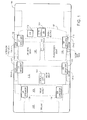
- FIG. 1 is a block diagram of a vehicle including a sound processing system.
- FIG. 2 is a block diagram or flow chart of a sound processing system.
- FIG. 3 is a block diagram or flow chart of a sound processing system.
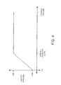
- FIG. 4 is a graph illustrating a suggested center channel volume attenuation curve for global low volume (below normal) listening.
- FIG. 5 is a block diagram or flow chart of a sound processing system.
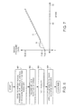
- FIG. 6 is a flow chart of a method for establishing a relationship between the sound pressure level (SPL) and speed in a sound processing system.
- SPL sound pressure level
- FIG. 7 is a graph illustrating an SPL and speed relationship.
- FIG. 8 is a block diagram or flow chart of a sound processing system.
- FIG. 9 illustrates mix ratios for a Logic 7® decoder.
- FIG. 10 illustrates mix ratios for a decoder.
- FIG. 11 illustrates mix ratios for a discrete decoder.
- FIG. 12 is a flow chart of a method for estimating coherence in a sound processing system.
- FIG. 13 is a flow chart of a method for spatializing a monaural signal in a sound processing system.
- FIG. 1 is a block diagram of a vehicle 100 including an audio or sound processing system (AS) 102, which may include any or a combination of the sound processing systems and methods described below.
- the vehicle 100 includes doors 104, a driver seat 109, a passenger seat 110, and a rear seat 111. While a four-door vehicle is shown including doors 104-1, 104-2, 104-3, and 104-4, the audio system (AS) 102 may be used in vehicles having more or fewer doors.
- the vehicle may be an automobile, truck, boat, or the like. Although only one rear seat is shown, larger vehicles may have multiple rows of rear seats. Smaller vehicles may have only one or more seats. While a particular configuration is shown, other configurations may be used including those with fewer or additional components.
- the audio system 102 improves the spatial characteristics of surround sound systems.
- the audio system 102 supports the use of a variety of audio components such as radios, CDs, DVDs, their derivatives, and the like.
- the audio system 102 may use 2-channel source material such as direct left and right, 5.1 channel, 6.2 channel, other source materials from a matrix decoder digitally encoded/decoded, discrete source material and the like.
- the amplitude and phase characteristics of the source material and the reproduction of specific sound field characteristics in the listening environment both play a key role in the successful reproduction of a surround sound field.
- the audio system 102 improves the reproduction of a surround sound field by controlling the amplitude, phase, and mixing ratios between discrete and passive decoder surround signals and/or the direct two-channel output signals.
- the amplitude, phase, and mixing ratios are controlled between the discrete and passive decoder output signals.
- the spatial sound field reproduction is improved for all seating locations by re-orientation of the direct, passive, and active mixing and steering parameters, especially in a vehicle environment.
- the mixing and steering ratios as well as spectral characteristics may be adaptively modified as a function of the noise and other environmental factors.
- information from the data bus, microphones, and other transduction devices may be used to control the mixing and steering parameters.
- the vehicle 100 has a front center speaker (CTR speaker) 124, a left front speaker (LF speaker) 113, a right front speaker (RF speaker) 115, and at least one pair of surround speakers.
- the surround speakers can be a left side speaker (LS speaker) 117 and a right side speaker (RS speaker) 119, a left rear speaker (LR speaker) 129 and a right rear speaker (RR speaker) 130, or a combination of speaker sets. Other speaker sets may be used. While not shown, one or more dedicated subwoofer or other drivers may be present. Possible subwoofer mounting locations include the trunk 105, below the seat (not shown) or the rear shelf 108.
- the vehicle 100 also has one or more microphones 150 mounted in the interior.
- Each CTR speaker, LF speaker, RF speaker, LS speaker, RS speaker, LR speaker, and RR speaker may include one or more speaker drivers such as a tweeter and a woofer.
- the tweeter and woofer may be mounted adjacent to each other in essentially the same location or in different locations.
- LF speaker 113 may include a tweeter located in door 104-1 or elsewhere at a height roughly equivalent to a side mirror or higher and may include a woofer located in door 104-1 beneath the tweeter.
- the LF speaker 113 may have other arrangements of the tweeter and woofer.
- the CTR speaker 124 is mounted in the front dashboard 107, but could be mounted in the roof, on or near the rear-view mirror, or elsewhere in the vehicle 100.
- FIG. 2 is a block diagram or a flow chart of a sound processing system 202.
- a head unit 212 provides a pair of audio signals to a sound processor 203.
- the head unit 212 may include a radio, a digital player such as a CD, DVD, or SACD, or the like.
- the audio signals generally are converted into the digital domain and then decoded to produce multiple distinct decoded signals for a crossbar matrix mixer 226. However, the digitally converted audio signals may be provided to the crossbar matrix mixer 226 without decoding.
- the audio signals may be provided to the crossbar matrix mixer without digital conversion.
- the audio signals may be filtered or unfiltered.
- the decoded signals and audio signals are mixed in various proportions using the crossbar matrix mixer 226.
- the proportions range from one or more of the audio signals (digitally converted or not, filtered or not) to one or more of the decoded signals, including combinations of the audio and decoded signals.
- Pre-filter 236 may apply additional tone and crossover filtering to the audio signals, as well as volume control and other controls.
- Sound processor 203 converts the manipulated audio and decoded signals into the analog domain.
- the analog output is amplified and routed to one or more speakers 288 such as the CTR speaker, LF speaker, RF speaker, LS speaker, RS speaker, LR speaker, and RR speaker as discussed in relation to FIG. 1. While a particular configuration and operation are shown, other configurations and operations may be used including those with fewer or additional components.
- the primary source head-unit 212 generates a left channel 214 and a right channel 218.
- the left and right channels may be processed similarly or differently. If the audio signals on the left channel 214 and right channel 218 are digital, the audio signals pass directly to pre-filter 236, decoder 228, or crossbar matrix mixer 226. If the audio signals on left channel 214 and right channel 218 are analog, the audio signals pass through one or more analog to digital converters (ADC) 220-1 and 220-2, and then pass to pre-filter 236, decoder 228, or crossbar matrix mixer 226.
- ADC analog to digital converters
- the pre-filter 236 includes one or more filters (not shown) that may provide conventional filter functions such as allpass, lowpass, highpass, bandpass, peak or notch, treble shelving, base shelving and/or other audio filter functions.
- left channel 214 and right channel 218 are input directly into crossbar matrix mixer 226.
- the left channel 214 and right channel 218 are input to decoder 228.
- the left channel 214 and right channel 218 are input to pre-filter 236.
- an optional secondary source 216 provides source signals from navigation unit 234 and cellular phone 242 to analog to digital converters (ADC) 220-3 and 220-4, respectively. These digital source signals are input into crossbar matrix mixer 226 or pre-filter 236.
- ADC analog to digital converters
- the decoder 228 From the primary-source digital inputs, such as direct from ADC 220-1 and ADC 220-2 or indirect from pre-filter 236, the decoder 228 generates multiple decoded signals that are output to crossbar matrix mixer 226. In one aspect, there are five decoded signals. In another aspect, there are seven decoded signals. There may be other multiples of decoded signals including those for a subwoofer.
- the decoder 228 may decode inherently digital inputs, such as DOLBY DIGITAL AC3® or DTS® signals, into multi-channel outputs.
- the decoder 228 may decode encoded 2-channel inputs, such as Dolby Pro Logic I®, Dolby Pro Logic II®, or DTS Neos 6® signals, into multi-channel outputs.
- the decoder 228 may apply other decoding methods, such as active matrix, to generate multi-channel outputs.
- Inherently digital inputs can result in 5.1 output - LF (left-front), CTR (center), RF (right-front), LR (left-rear), RR (right-rear), and LFE (low frequency).
- Inherently digital inputs also can result in 6.2 output - LF, CTR, RF, LS (left-side), RS (right-side), LR, RR, left LFE, and right LFE.
- Inherently digital inputs can result in other outputs.
- an active matrix processed 2-channel input can result in 4.0 output - LF, CTR, RF, and S (surround)).
- the channels output by these types of decoders are referred to as discrete. Other multi-channel outputs may result.
- the outputs from decoder 228 can be input to crossbar matrix mixer 226.
- the crossbar matrix mixer 226 outputs two or more summed signals 258. In one aspect, there are four or more output signals 258. There may be other multiples of output signals.
- the crossbar matrix mixer 226 may include individual channel inputs and may include virtual channel processing. The virtual channels may be further utilized to process any signal presented in the crossbar matrix for various complex sound effects.
- the crossbar matrix mixer 226 may have head-related transfer functions and cross-channel cancellation processing that may be utilized by the virtual channels and also included in the crossbar matrix to create a virtual sound image or signal locations distant from the actual speaker drivers.
- Mixed output signals 258 from crossbar matrix mixer 226 are input to post-filter 260, which includes one or more digital filters (not shown) that provide conventional filter functions such as allpass, lowpass, highpass, bandpass, peak or notch, treble shelving, base shelving, other audio filter functions, or a combination.
- the filtration performed by post-filter 260 is in response to input signal 261, which may include: vehicle operation parameters such as a vehicle speed and engine revolutions-per-minute (RPM); sound settings such as tone level, bass level, treble level, and global volume from the head unit 212; input sound pressure level (SPL) from interior microphones 150-1, 150-2, and/or 150-3 (see Fig. 1); or a combination.
- vehicle operation parameters such as a vehicle speed and engine revolutions-per-minute (RPM); sound settings such as tone level, bass level, treble level, and global volume from the head unit 212; input sound pressure level (SPL) from interior microphones 150-1, 150-2, and/or 150-3 (see Fig
- a two channel filter 236 is placed before the decoder 228.
- a multi-channel post-filter 260 is placed after the crossbar matrix mixer 226 for use with digital decoders that process DOLBY DIGITAL AC3® and DTS® signals.
- the multi-channel post-filter 260 may have three or more output channels.
- volume gain 264 applies global volume attenuation to all signals output or localized volume attenuation to specific channels.
- the gain of volume gain block 264 is determined by vehicle input signals 266, which are indicative of vehicle operation parameters.
- vehicle input signals 266 include vehicle speed provided by a vehicle data bus (not shown).
- vehicle input signals 266 include vehicle state signals such as convertible top up, convertible top down, vehicle started, vehicle stopped, windows up, windows down, ambient vehicle noise (SPL) from interior microphone 150-1 placed near the listening position, door noise (SPL) from door microphone 150-2 placed in the interior of a door, and the like.
- Other input signals such as fade, balance, and global volume from the head unit 212, the navigation unit 234, the cellular phone 242, or a combination may be used.
- An output 268 of volume gain 264 is input to a delay 270.
- An output 272 of delay is input to a limiter 274.
- An output 276 of the limiter 274 is input to a digital to analog (DAC) converter 278.
- the limiter 274 may employ clip detection 280.
- An output 282 of the DAC 278 is input to an amplifier 284.
- An output 286 of the amplifier 284 is input to one or more speakers 288.
- the sound processing system 202 can decode digitally encoded material (DOLBY DIGITAL AC3®, DTS®, and the like) or originally analog material, such as monaural, stereo, or encoded tracks that are converted into the digital domain.
- the decoder can employ one or more active matrix decoding techniques, including DOLBY PRO LOGIC® or LOGIC 7®, and various environment effects, including hall, club, theater, etc.
- active matrix decoding the decoder converts the left and right channel inputs to center, left, right, and surround channel outputs.
- the decoder can output a low-frequency channel, which is routed to a subwoofer.
- Active matrix decoding applies digital processing techniques to significantly increase the separation between the center, left, right, and surround channels by manipulating the input signals.
- active matrix channel separation is about 30 db between all four channels.
- Active matrix processing can be employed where coefficients change with time, source, or any other parameter.
- Virtual center channels can be synthesized from left and right speakers.
- Passive matrix processing uses a resistive network to manipulate analog input signals. Passive matrix processing also may be achieved in the digital domain from digitized input. Passive matrix processing may be implemented in the crossbar matrix mixer 226 or elsewhere in the sound processing system. Passive matrix processing may be used without active matrix processing, as in systems without a surround sound decoder, or in combination with a surround sound decoder. In one aspect, the user selects between active decoding or passive processing. In another aspect, the processing system selects the type of processing based on the audio signals.
- passive matrix processing of a digitized signal is beneficial in home and automobile environments and especially for degraded signals as described below.
- passive matrix processing Unlike active matrix processing, which can achieve 30 db of separation between the channels, passive matrix processing generally has >40 db of separation between the left and right and center and surround channels, but only about 3 db of separation between adjacent channels, such as the left/right and center, and left/right and surround.
- active matrix processing achieves about an order of magnitude greater separation than passive matrix.
- passive matrix processing results in all speakers passing the audio signal.
- passive matrix processing may be used to reduce slamming and other undesirable effects of stereo to mono blending for sources including amplitude modulation (AM) radio, frequency modulation (FM) radio, CD, and cassette tapes.
- AM amplitude modulation
- FM frequency modulation
- the crossbar matrix mixer 226 mixes N output channels from the left and right audio input channels 214 and 218.
- the passive matrix includes matrix coefficients that do not change over time.
- N is equal to five or seven.
- the vehicle sound system preferably includes left front (LF), right front (RF), right side (RS) or right rear (RR), left side (LS) or left rear (LR) and center (CTR) speakers.
- N is equal to seven, the vehicle sound system has both side and rear speaker pairs.
- distortion limiting filters may be used.
- Sound processing system 202 may incorporate one or more distortion limiting filters in the pre-filter 236 or post-filter 260.
- these filters are set based on vehicle state information and user settings in addition or in-lieu of the properties of the audio signal itself.
- a predetermined volume level can be a global volume setting preset by a manufacturer or selected by a user of the sound processing system.
- the predetermined volume also can be a sound pressure level as discussed.
- a high or elevated volume level is when the global volume setting exceeds a high volume threshold.
- the attenuation may be applied to signals with previously applied filter gain or the "raw" signal. Attenuation may be accomplished by coupling the treble shelf, base shelf, or notch filter (or any combination of these filter functions or others) to the global volume position, and engaging the attenuation filters as desired.
- tone filter attenuation may also be improved at predetermined or elevated listening levels by tone filter attenuation.
- This attenuation may be applied to previously tone compensated signal or the "raw" signal.
- Tone filter attenuation may be incorporated into filter block 236 or 260.
- the attenuation may be accomplished by coupling one or multiple filters (treble shelf, base shelf, notch, or others) to the bass, treble, or midrange tone controls, and engaging the attenuation filters as desired.
- Attenuation may also be applied by dynamically compensating the amount of attenuation through the use of SPL information provided by an in-car microphone, such as the interior microphone 150-1 (see FIG. 1).
- the crossbar matrix mixer 226 performs adaptive mixing to alter the inter-channel mixing ratios, steering angles, and filter parameters between the discrete channel outputs from decoder 228 to improve spatial balance and reduce steering artifacts.
- Spatial balance can be thought of as the evenness of the soundstage created and the ability to locate specific sounds in the soundstage.
- Steering artifacts may be thought of as audible discontinuities in the soundstage, such as when you hear a portion of the signal from one speaker location and then hear it shift to another speaker location.
- the steering angles are overly aggressive; you can hear over-steering, or "pumping," which changes the volume of the signal.
- the mixer can mix direct, decoded: or passively processed signals with discrete, non-steered, or partially-steered signals to improve the spatial balance of the sound heard at each passenger location. This improvement can be applied to music signals, video signals, and the like.
- FIG. 3 is a block diagram or flow chart of a sound processing system 302.
- the sound processing system 302 has a sound processor 303 that receives left and right channel signals 314 and 318 from a head-unit or other source (not shown).
- the left and right channel signals 314 and 318 are input to analog-to-digital converters (ADC) 320-1 and 320-2.
- ADC analog-to-digital converters
- Outputs of the ADC 320-1 and 320-2 are input to a decoder 328.
- Outputs of the decoder 328 are input to a crossbar matrix mixer 326, which generates the LF out, RF out, RS out /RR out, LS out /LR out, and CTR out output signals 344, 345, 346, 347 and 343, respectively.
- CTR out signal 343 is output to a center channel volume compensator 341, which also receives a volume input 361 from a head unit or another source such as a vehicle data bus.
- the center channel compensator 341 reduces the gain of the center channel for low volume settings in relation to the left and right outputs (LF out, RF out, RS out , LS out , RR out , and LR out ).
- Low volumes setting are when the global volume setting is equal or less than a threshold volume, which may be predetermined or correlated to another parameter.
- FIG. 4 is a graph illustrating a suggested center channel gain/volume relationship.
- the center channel volume compensator 341 provides attenuation of the center channel for low global volume levels. More particularly, the center channel volume compensator 341 attenuates the center channel for lower than normal listening levels. Without attenuation at low global volume settings, the music sounds like it emanates only from the center speaker. The center speaker essentially masks the other speakers in the audio system. By attenuating the center speaker at lower global volume levels, improved sound quality is provided by the sound processor 302. The music sounds like it emanates from all the speakers.
- front and rear channel volume compensators 346 and 348 may be used to increase the volume on the LF, RF, LS, LR, and RS, RR speakers 113, 115, 117, 129, 119, and 130 in relation to the center speaker 124 (see FIG. 1).
- the volume compensation curve applied to the front and rear channels could be the inverse of that shown in FIG. 4.
- FIG. 5 is a block diagram or flow chart of a sound processing system 502 is shown that adjusts for variations in background sound pressure level (SPL). As speed increases, the background SPL and road noise increase. The road noise tends to mask or cancel sound coming from door-mounted speakers.
- the sound processing system 502 applies additional gain to the door-mounted speakers as a function of the vehicle operation parameters such as speed, the SPL measurements from an interior microphone such as the door mounted microphone 150-2 or the interior microphone 150-1 (see FIG. 1), or a combination.
- SPL background sound pressure level
- the sound processing system 502 receives left and right channel signals 514 and 518 from a head unit or other source (not shown).
- the left and right channel signals 514 and 518 are input to analog to digital converters (ADC) 520-1 and 520-2.
- ADC analog to digital converters
- Outputs of ADC's 520-1 and 520-2 are input to decoder 528.
- Outputs of the decoder 528 are input to a crossbar matrix mixer 526.
- the crossbar matrix mixer 526 generates LF, RF, LS/LR, RS/RR, and CTR output signals. The signals that are sent to door-mounted speakers are adjusted to account for changes in the SPL.
- the door-mounted speakers may be the LF and RF only, the LS and RS only, or the LF, RF, LS, and RS, or another combination of speakers.
- the LF and RF speakers may be in the doors and the LR and RR are in the rear deck.
- the LF and RF speakers may be in the kick panels, and the LS, RS, LR and RR speakers are door-mounted.
- the LF, RF, LR, and RR speakers are all in the doors.
- the CTR speaker is not door-mounted.
- a single surround speaker is mounted in the rear shelf 108 (see FIG. 1).
- the outputs of the crossbar matrix mixer 526 that are associated with door-mounted speakers are output to a door-mounted speaker compensator 531.
- the door-mounted compensator 531 also receives vehicle status input 566, which may be received from a vehicle data bus or any other source.
- the vehicle status input 566 may be the vehicle speed, the door noise, and the like.
- the compensator 531 may receive a SPL signal in real-time from a microphone 150-2 mounted in the interior of a door or microphone 150-1 mounted in the interior of the vehicle. In this manner, volume correction may be applied as a function of vehicle speed and door SPL levels, or SPL level alone.
- FIG. 6 is a flow chart of a method for establishing a relationship between sound pressure level (SPL) and vehicle speed in a sound processing system.
- SPL sound pressure level
- Ambient SPL is measured 651 in the vehicle with the engine running at 0 mph and with the head unit and other audio sources turned off.
- the SPL is recorded 652 as a function of speed.
- the results are plotted 653. Linear, non-linear, or any other form of curve fitting may be employed on the measured data. Adjustments are applied 654 to door-mounted speakers.
- FIG. 7 is a graph illustrating an SPL to vehicle speed relationship. Dotted line A shows uncorrected gain for all speakers as a function of speed. Solid line B shows corrected gain for door-mounted speakers.
- the door-mounted speaker compensator 531 (see FIG. 5) employs the corrected gain for door-mounted speakers to improve audio quality.
- FIG. 8 is a block diagram or flow chart of a sound processing system 802 having a virtual center channel.
- FIG. 9 illustrates mix ratios for a Logic7® decoder.
- FIG. 10 illustrates alternate mix ratios for a decoder.
- FIG. 11 illustrates mix ratios for a discrete decoder.
- the sound processing system 802 generates a virtual center channel 140 (see FIG. 1) for rear seat occupants. Usually, there is no center speaker in the rear of a vehicle. Additionally, the front seats tend to block the sound from the center speaker reaching rear seat occupants. This problem is more apparent in vehicles having multiple rows of seating such as sport utility vehicles and vans.
- a virtual center channel is created by modifying the ratios of direct and actively decoded or passively processed signals.
- the steering, gain, and/or signal delay for selected audio channels may also be modified.
- the sound quality of the virtual center channel may be improved by utilizing various mix ratios of decoded, passive matrix processed, and direct signals singularly or in combination that are processed with band limited first to fourth order all-pass filters (crossovers).
- crossbar matrix mixer 826 generates the virtual rear seat center channel 140 using the LS IN and RS IN signals in combination with either the LF IN and RF IN signals.
- the crossbar matrix mixer 826 generates the virtual rear center speaker 140 by mixing 60 % LS IN with 40% LF IN and by mixing 60 % RS IN with 40 % RF IN. Other mix ratios may be used.
- the LF IN and RF IN signals could be the direct left and right channel signals that do not pass through the decoder.
- the left and right channel signals contain sufficient information to generate the virtual center channel for use with typical stereo reproduction and to generate the modified signals to alter the side and rear signals.
- the crossbar matrix mixer 826 also generates the virtual rear seat center channel 140 using the LS IN and RS IN signals in combination with either the LF IN and RF IN signals or the CTR IN signal.
- the crossbar matrix mixer 826 generates the virtual rear center speaker 140 by mixing 80 % LS IN with 20% LF IN and by mixing 80 % RS IN with 20 % RF IN.
- these mix ratios are used when either or both LF IN and RF IN have strong CTR components. Other mix ratios may be used.
- Some decoders have significant center channel interaction that bleeds into LF IN and RF IN. For these decoders, the LF IN and RF IN signals alone may be used to generate the phantom center.
- the crossbar matrix mixer 826 generates the virtual rear center speaker 140 by mixing LS IN and CTR IN and by mixing RS IN and CTR IN signals.
- the crossbar matrix mixer 826 generates the virtual rear center speaker 140 by mixing 80% LS IN with 20% CTR IN and by mixing 80% RS IN with 20% CTR IN .
- Other mix ratios may be used.
- the mix ratio may vary depending upon the particular vehicle and/or audio system.
- the RS and LS outputs pass through an allpass network 810.
- the virtual rear seat center channel may not image well.
- the virtual rear channel may sound like it emanates from a source that is positioned low in the vehicle especially if generated from low-mounted door speakers.
- the center soundfield image is "blurred" and not reproduced at the location intended. Allpass networks improve the imaging and stability of the virtual center, making the listener believe the center sound stage is located higher in the vehicle such as nearer ear level.
- the RS and LS outputs pass through an allpass network 825.
- the size (diameter and depth) of the CTR speaker may be restricted in comparison to the front and rear door speaker locations. With a smaller size, the CTR channel speaker is not capable of reproducing the lower frequencies as well as the larger door speakers. The resulting effect of this restriction causes a "spatial blurring" of the CTR speaker sound image as the CTR signal transcends from high to low frequencies or vice-a-versa.
- the CTR channel's lower frequencies are perceived as emanating from the smaller CTR speaker. The imaging and stability of the center channel lower frequencies are improved.
- FIG. 12 is a flow chart of a method for estimating coherence in a sound processing system.
- Coherence is the proportion of stereo and monaural signals in the incoming audio signals.
- the degree or steering of active matrix decoding is reduced during the processing of mixed monaural-stereo or monaural only signals. While reducing the amount of applied steering decreases the sound quality in comparison to fully steered stereo signals, steering reduction is preferable to slamming and other acoustic abnormalities that often result from fully steering mixed or monaural signals.
- the left and right channel inputs are band-limited 1255.
- a value of 0 is assigned to a pure stereo signal (no signal overlap between channels) and a value of 1 is assigned to a pure monaural signal (complete overlap between channels).
- Values between 0 and 1 are assigned to mixed monaural/stereo signals in direct proportion to their stereo versus monaural character.
- the coherence C is calculated 1256. Estimates of steering angles for the left channel output verses the right channel output and for the center channel output verses the surround channel output are determined 1257. The center verses surround and the left verses right steering angles are limited 1259 as a function of the calculated coherence value C.
- the system transitions between full active steering verses limited steering angle processing.
- steering angles are continually optimized for the available received signal.
- smoothing the steering angle transitions slamming is reduced.
- the coherence estimator When the low-frequency bass content of signals, even those that are otherwise purely stereo, contains an overlap in the bass frequencies due to the non-directional character of base frequencies, the coherence estimator first band-limits the left and right input signals before calculating the coherence value. In this fashion, the coherence estimate is not skewed by music with large bass content.
- FIG. 13 is a flow chart of a method for spatializing a monaural signal in a sound processing system.
- the coherence estimator (see FIG. 12) is adapted for use with the monaural spatializer.
- This monaural spatializer may be used to add ambience to a pure or nearly pure monaural signal.
- the monaural signals can be processed by an active surround processor such as Dolby Pro Logic I®, Dolby Pro Logic II®, DTS Neos 6® processors, and the like.
- an active surround processor such as Dolby Pro Logic I®, Dolby Pro Logic II®, DTS Neos 6® processors, and the like.
- monaural sound quality can be improved. While beneficial to the automotive platform, home systems may also benefit from the increased sound quality achieved by actively processing the virtual stereo signals created from pure, or nearly pure, monaural feeds.
- a synthetic surround ( ambience) signal S f is continuously formed 1363.
- S f can be derived by band-limiting the L raw and R raw input signals to about 7 kHz and above, summing these L and R band-limited signals, and dividing this sum by two.
- the input signals are first summed and divided prior to band-limiting.
- a coherence estimate value (C) may be continuously calculated 1365 for the L and R input signals as described above.
- the raw input signals (L raw and R raw ) are continuously modified 1367 in response to the raw input signals and a weighted sum of the S f signal formation 1363 and the coherence calculation 1365 to generate virtual stereo signals L t and R t .
- the virtual stereo signals L t and R t are output 1369 to an active decoder for surround sound processing.
- the monaural spatializer may be designed so that from a pure, or nearly pure monaural signal, virtual stereo signals are generated that can produce LF and RF signals that are from about 3 to about 6 db down from the CTR signal, and a surround signal that is about 6 db down from the CTR signal.
- the virtual stereo signals L t and R t may be input to an active decoder.
- L t and R t may be derived from monaural or nearly monaural L raw and R raw signals that are band-limited to about 7 kHz thus generating L bl and R bl .
- the weighting factors X and Y may be varied depending on the surround sound effects desired.
- the coherence estimator determines a signal to be purely or nearly pure monaural in character
- surround information is added to the signal prior to active decoding.
- C approaches 0 (pure stereo)
- the amount of synthetic surround is reduced, thus eliminating virtual stereo in favor of true stereo as the stereo character of the signal increases.
- a received signal strength estimator may also be used to alter the degree or steering of active matrix processing.
- the sound processing systems are advantageous for automotive sound systems. However, in many instances, they may be beneficially used in a home theater environment. These systems also may be implemented in the vehicle through the addition of add-on devices or may be incorporated into vehicles with the requisite processing capabilities already present.
- a single digital processing system of sufficient functionality can implement the disclosed embodiments, thus eliminating the requirement for multiple analog and/or digital processors.
- a digital processor can optionally transform any appropriate digital feed, such as from a compact disc, DVD, SACD, or satellite radio.
- the digital processor can incorporate an analog to digital converter to process an analog signal, such as a signal previously converted from digital to analog, an AM or FM radio signal, or a signal from an inherently analog device, such as a cassette player.
- the sound processing systems can process 2-channel source material, and may also process other multiple channels such as, 5.1 and 6.2 multi-channel signals if an appropriate decoder is used.
- the system can improve the spatial characteristics of surround sound systems from multiple sources.
- the sound processing systems can process sound-inputs from any additional secondary source, such as cell phones, radar detectors, scanners, citizens band (CB) radios, and navigation systems.
- the digital primary source music signals include DOLBY DIGITAL AC3®, DTS®, and the like.
- the analog primary source music signals include monaural, stereo, encoded, and the like.
- the secondary source signals may be processed along with the music signals to enable gradual switching between primary and secondary source signals. This is advantageous when one is driving a vehicle and desires music to fade into the background as a call is answered or as a right turn instruction is received from the navigation system.
- the sound processing systems include methods to improve the reproduction of a surround sound field by controlling the amplitude, phase, and mixing ratios of the music signals as they are processed from the head-unit outputs to the amplifier inputs. These systems can deliver an improved spatial sound field reproduction for all seating locations by re-orientation of the direct, passive, or active mixing and steering parameters according to occupant location. The mixing and steering parameters according to occupant location. The mixing and steering ratios, as well as spectral characteristics, may also be modified as a function of vehicle speed and/or noise in an adaptive nature.
Landscapes
- Engineering & Computer Science (AREA)
- Physics & Mathematics (AREA)
- Acoustics & Sound (AREA)
- Signal Processing (AREA)
- General Physics & Mathematics (AREA)
- Mathematical Optimization (AREA)
- Mathematical Physics (AREA)
- Pure & Applied Mathematics (AREA)
- Theoretical Computer Science (AREA)
- Mathematical Analysis (AREA)
- Algebra (AREA)
- Stereophonic System (AREA)
- Fittings On The Vehicle Exterior For Carrying Loads, And Devices For Holding Or Mounting Articles (AREA)
- Circuit For Audible Band Transducer (AREA)
Applications Claiming Priority (2)
| Application Number | Priority Date | Filing Date | Title |
|---|---|---|---|
| US208930 | 2002-07-31 | ||
| US10/208,930 US7451006B2 (en) | 2001-05-07 | 2002-07-31 | Sound processing system using distortion limiting techniques |
Publications (3)
| Publication Number | Publication Date |
|---|---|
| EP1389892A2 true EP1389892A2 (de) | 2004-02-18 |
| EP1389892A3 EP1389892A3 (de) | 2007-08-15 |
| EP1389892B1 EP1389892B1 (de) | 2018-11-21 |
Family
ID=30770585
Family Applications (1)
| Application Number | Title | Priority Date | Filing Date |
|---|---|---|---|
| EP03017368.6A Expired - Lifetime EP1389892B1 (de) | 2002-07-31 | 2003-07-31 | Klangverarbeitungssystem mit Techniken zur Verzerrungsbegrenzung |
Country Status (5)
| Country | Link |
|---|---|
| US (1) | US7451006B2 (de) |
| EP (1) | EP1389892B1 (de) |
| JP (2) | JP4408670B2 (de) |
| KR (1) | KR100996571B1 (de) |
| CA (1) | CA2436388C (de) |
Cited By (5)
| Publication number | Priority date | Publication date | Assignee | Title |
|---|---|---|---|---|
| EP1596627A3 (de) * | 2004-05-04 | 2005-12-07 | Bose Corporation | Gerät zur Wiedergabe von Zentralkanalinformationen in einem Mehrkanaltonsystem für ein Fahrzeug |
| EP2271138A1 (de) * | 2004-08-17 | 2011-01-05 | Harman International Industries, Incorporated | Klangverarbeitungssystem zur Konfiguration von Audiosignalen in einem Fahrzeug |
| US8472638B2 (en) | 2001-05-07 | 2013-06-25 | Harman International Industries, Incorporated | Sound processing system for configuration of audio signals in a vehicle |
| US9560448B2 (en) | 2007-05-04 | 2017-01-31 | Bose Corporation | System and method for directionally radiating sound |
| CN110096831A (zh) * | 2019-05-10 | 2019-08-06 | 核芯互联科技(青岛)有限公司 | 数模混合仿真中链接节点插入方法及装置 |
Families Citing this family (18)
| Publication number | Priority date | Publication date | Assignee | Title |
|---|---|---|---|---|
| GB2378626B (en) * | 2001-04-28 | 2003-11-19 | Hewlett Packard Co | Automated compilation of music |
| CA2773294C (en) * | 2002-05-03 | 2013-03-12 | Harman International Industries, Incorporated | Sound detection and localization system |
| KR100469919B1 (ko) * | 2002-09-12 | 2005-02-21 | 주식회사 아이필소닉 | 다중선택 기능을 갖는 음향 장치 및 사운드 신호 제어 장치 |
| US8160888B2 (en) * | 2005-07-19 | 2012-04-17 | Koninklijke Philips Electronics N.V | Generation of multi-channel audio signals |
| US8135137B2 (en) * | 2006-03-13 | 2012-03-13 | Panasonic Corporation | Sound image localization apparatus |
| KR101015037B1 (ko) * | 2006-03-29 | 2011-02-16 | 돌비 스웨덴 에이비 | 오디오 디코딩 |
| JP4943806B2 (ja) * | 2006-10-18 | 2012-05-30 | パイオニア株式会社 | 音響装置、その方法、そのプログラム及びその記録媒体 |
| CA2613873C (en) * | 2007-05-03 | 2008-10-28 | Imperial Oil Resources Limited | An improved process for recovering solvent from asphaltene containing tailings resulting from a separation process |
| US8369541B2 (en) * | 2008-06-10 | 2013-02-05 | Polycom, Inc. | Distributed audio signal processing system having virtual channels |
| EP2190221B1 (de) * | 2008-11-20 | 2018-09-12 | Harman Becker Automotive Systems GmbH | Audiosystem |
| US8411877B2 (en) * | 2009-10-13 | 2013-04-02 | Conexant Systems, Inc. | Tuning and DAC selection of high-pass filters for audio codecs |
| US9324337B2 (en) * | 2009-11-17 | 2016-04-26 | Dolby Laboratories Licensing Corporation | Method and system for dialog enhancement |
| GB201121075D0 (en) * | 2011-12-08 | 2012-01-18 | Sontia Logic Ltd | Correcting non-linear frequency response |
| JP6501223B2 (ja) * | 2015-05-21 | 2019-04-17 | アルパイン株式会社 | 電子装置、電子システム、音声出力プログラムおよび音声出力方法 |
| US9820073B1 (en) | 2017-05-10 | 2017-11-14 | Tls Corp. | Extracting a common signal from multiple audio signals |
| US10869128B2 (en) | 2018-08-07 | 2020-12-15 | Pangissimo Llc | Modular speaker system |
| TWI768457B (zh) * | 2020-09-03 | 2022-06-21 | 瑞昱半導體股份有限公司 | 音訊處理晶片、多聲道系統與音訊處理方法 |
| CN114173274B (zh) * | 2020-09-10 | 2024-08-09 | 瑞昱半导体股份有限公司 | 音频处理芯片、多声道系统与音频处理方法 |
Family Cites Families (133)
| Publication number | Priority date | Publication date | Assignee | Title |
|---|---|---|---|---|
| US3845572A (en) | 1972-08-02 | 1974-11-05 | Singer Co | Modular vehicle trainer sound system having a plurality of separately controllable sound generators and a polyphonic speaker array |
| US4251688A (en) | 1979-01-15 | 1981-02-17 | Ana Maria Furner | Audio-digital processing system for demultiplexing stereophonic/quadriphonic input audio signals into 4-to-72 output audio signals |
| JPS56132804A (en) * | 1980-03-22 | 1981-10-17 | Sharp Corp | Operational tone quality control circuit |
| JPS60107998A (ja) | 1983-11-16 | 1985-06-13 | Nissan Motor Co Ltd | 車両用音響装置 |
| US4641344A (en) | 1984-01-06 | 1987-02-03 | Nissan Motor Company, Limited | Audio equipment |
| JPS60145714U (ja) | 1984-03-07 | 1985-09-27 | 日本電信電話株式会社 | アンテナ方向調整装置 |
| US4704728A (en) | 1984-12-31 | 1987-11-03 | Peter Scheiber | Signal re-distribution, decoding and processing in accordance with amplitude, phase, and other characteristics |
| US4799260A (en) | 1985-03-07 | 1989-01-17 | Dolby Laboratories Licensing Corporation | Variable matrix decoder |
| US4941177A (en) | 1985-03-07 | 1990-07-10 | Dolby Laboratories Licensing Corporation | Variable matrix decoder |
| US5046098A (en) | 1985-03-07 | 1991-09-03 | Dolby Laboratories Licensing Corporation | Variable matrix decoder with three output channels |
| JPS621441U (de) | 1985-06-20 | 1987-01-07 | ||
| JPH0520080Y2 (de) | 1986-08-20 | 1993-05-26 | ||
| JPH0538000Y2 (de) | 1987-01-22 | 1993-09-27 | ||
| JPS63177699U (de) | 1987-05-08 | 1988-11-17 | ||
| US4759066A (en) | 1987-05-27 | 1988-07-19 | Polk Investment Corporation | Sound system with isolation of dimensional sub-speakers |
| US4972482A (en) * | 1987-09-18 | 1990-11-20 | Sanyo Electric Co., Ltd. | Fm stereo demodulator |
| US4829299A (en) | 1987-09-25 | 1989-05-09 | Dolby Laboratories Licensing Corporation | Adaptive-filter single-bit digital encoder and decoder and adaptation control circuit responsive to bit-stream loading |
| US4862502A (en) | 1988-01-06 | 1989-08-29 | Lexicon, Inc. | Sound reproduction |
| US5189703A (en) * | 1988-01-06 | 1993-02-23 | Lucasarts Entertainment Company | Timbre correction units for use in sound systems |
| US4932059A (en) | 1988-01-11 | 1990-06-05 | Fosgate Inc. | Variable matrix decoder for periphonic reproduction of sound |
| JPH0228200U (de) | 1988-08-12 | 1990-02-23 | ||
| JPH0623119Y2 (ja) | 1989-01-24 | 1994-06-15 | パイオニア株式会社 | サラウンド方式ステレオ再生装置 |
| US5146507A (en) | 1989-02-23 | 1992-09-08 | Yamaha Corporation | Audio reproduction characteristics control device |
| JPH03188707A (ja) * | 1989-12-19 | 1991-08-16 | Pioneer Electron Corp | 音響再生装置 |
| US5109419A (en) | 1990-05-18 | 1992-04-28 | Lexicon, Inc. | Electroacoustic system |
| US5504819A (en) | 1990-06-08 | 1996-04-02 | Harman International Industries, Inc. | Surround sound processor with improved control voltage generator |
| DE69130169T2 (de) | 1990-06-08 | 1999-04-15 | Harman International Industries, Inc., Northridge, Calif. | Raumklang-prozessor |
| US5295189A (en) | 1990-06-08 | 1994-03-15 | Fosgate James W | Control voltage generator for surround sound processor |
| US5339363A (en) | 1990-06-08 | 1994-08-16 | Fosgate James W | Apparatus for enhancing monophonic audio signals using phase shifters |
| US5666424A (en) | 1990-06-08 | 1997-09-09 | Harman International Industries, Inc. | Six-axis surround sound processor with automatic balancing and calibration |
| US5172415A (en) | 1990-06-08 | 1992-12-15 | Fosgate James W | Surround processor |
| US5625696A (en) | 1990-06-08 | 1997-04-29 | Harman International Industries, Inc. | Six-axis surround sound processor with improved matrix and cancellation control |
| US5428687A (en) | 1990-06-08 | 1995-06-27 | James W. Fosgate | Control voltage generator multiplier and one-shot for integrated surround sound processor |
| KR920004817Y1 (ko) * | 1990-08-14 | 1992-07-20 | 삼성전자 주식회사 | 음성다중방식의 공용수신장치 |
| US5119422A (en) | 1990-10-01 | 1992-06-02 | Price David A | Optimal sonic separator and multi-channel forward imaging system |
| US5274740A (en) | 1991-01-08 | 1993-12-28 | Dolby Laboratories Licensing Corporation | Decoder for variable number of channel presentation of multidimensional sound fields |
| KR100228688B1 (ko) | 1991-01-08 | 1999-11-01 | 쥬더 에드 에이. | 다차원 음장용 인코우더/디코우더 |
| US5136650A (en) | 1991-01-09 | 1992-08-04 | Lexicon, Inc. | Sound reproduction |
| KR970000147B1 (ko) * | 1991-01-31 | 1997-01-04 | 삼성전자 주식회사 | 다중음성기록재생시스템 |
| US5594800A (en) * | 1991-02-15 | 1997-01-14 | Trifield Productions Limited | Sound reproduction system having a matrix converter |
| US5161197A (en) | 1991-11-04 | 1992-11-03 | Lexicon, Inc. | Acoustic analysis |
| US5199075A (en) | 1991-11-14 | 1993-03-30 | Fosgate James W | Surround sound loudspeakers and processor |
| JPH05191899A (ja) | 1992-01-16 | 1993-07-30 | Pioneer Electron Corp | ステレオサラウンド装置 |
| US5333201A (en) | 1992-11-12 | 1994-07-26 | Rocktron Corporation | Multi dimensional sound circuit |
| US5319713A (en) | 1992-11-12 | 1994-06-07 | Rocktron Corporation | Multi dimensional sound circuit |
| US5357574A (en) * | 1992-12-14 | 1994-10-18 | Ford Motor Company | Coherent signal generation in digital radio receiver |
| ES2149235T3 (es) | 1993-01-22 | 2000-11-01 | Koninkl Philips Electronics Nv | Transmision digital en 3 canales de señales estereofonicas izquierda y derecha y una señal central. |
| CA2112171C (en) | 1993-02-25 | 2003-10-21 | Bradley Anderson Ballard | Dsp-based vehicle equalization design system |
| US5581621A (en) | 1993-04-19 | 1996-12-03 | Clarion Co., Ltd. | Automatic adjustment system and automatic adjustment method for audio devices |
| JPH06311589A (ja) | 1993-04-19 | 1994-11-04 | Clarion Co Ltd | オーディオ装置のネットワーク帯域表示方法 |
| JPH06311581A (ja) | 1993-04-19 | 1994-11-04 | Clarion Co Ltd | アンプのゲイン調整システム |
| SG43996A1 (en) | 1993-06-22 | 1997-11-14 | Thomson Brandt Gmbh | Method for obtaining a multi-channel decoder matrix |
| US5463424A (en) | 1993-08-03 | 1995-10-31 | Dolby Laboratories Licensing Corporation | Multi-channel transmitter/receiver system providing matrix-decoding compatible signals |
| US5386473A (en) | 1994-01-21 | 1995-01-31 | Harrison; Robert W. | Passive surround sound circuit |
| US5497425A (en) | 1994-03-07 | 1996-03-05 | Rapoport; Robert J. | Multi channel surround sound simulation device |
| US5717765A (en) | 1994-03-07 | 1998-02-10 | Sony Corporation | Theater sound system with upper surround channels |
| US6144747A (en) | 1997-04-02 | 2000-11-07 | Sonics Associates, Inc. | Head mounted surround sound system |
| US6853732B2 (en) | 1994-03-08 | 2005-02-08 | Sonics Associates, Inc. | Center channel enhancement of virtual sound images |
| FR2719258B1 (fr) * | 1994-04-27 | 1996-07-19 | Hutchinson | Dispositif de roulage à plat pour véhicule automobile. |
| US5638452A (en) | 1995-04-21 | 1997-06-10 | Rocktron Corporation | Expandable multi-dimensional sound circuit |
| US5761313A (en) | 1995-06-30 | 1998-06-02 | Philips Electronics North America Corp. | Circuit for improving the stereo image separation of a stereo signal |
| KR0128064Y1 (ko) | 1995-08-18 | 1998-11-02 | 김광호 | 서브우퍼신호 합성기능을 가지는 서라운드 음향신호 재생장치 |
| JPH0962271A (ja) | 1995-08-22 | 1997-03-07 | Mitsubishi Electric Corp | 車載電子装置 |
| JP2956545B2 (ja) * | 1995-08-28 | 1999-10-04 | ヤマハ株式会社 | 音場制御装置 |
| US5930370A (en) | 1995-09-07 | 1999-07-27 | Rep Investment Limited Liability | In-home theater surround sound speaker system |
| US5708719A (en) | 1995-09-07 | 1998-01-13 | Rep Investment Limited Liability Company | In-home theater surround sound speaker system |
| US6118876A (en) | 1995-09-07 | 2000-09-12 | Rep Investment Limited Liability Company | Surround sound speaker system for improved spatial effects |
| KR0174084B1 (ko) | 1995-09-25 | 1999-04-01 | 이준 | Mpeg-2 다채널 오디오 복호화기의 역변환기 |
| JP2926679B2 (ja) | 1995-10-12 | 1999-07-28 | 三菱電機株式会社 | 車載音響装置 |
| US5798818A (en) | 1995-10-17 | 1998-08-25 | Sony Corporation | Configurable cinema sound system |
| US5642423A (en) | 1995-11-22 | 1997-06-24 | Sony Corporation | Digital surround sound processor |
| US5956674A (en) | 1995-12-01 | 1999-09-21 | Digital Theater Systems, Inc. | Multi-channel predictive subband audio coder using psychoacoustic adaptive bit allocation in frequency, time and over the multiple channels |
| US5771295A (en) * | 1995-12-26 | 1998-06-23 | Rocktron Corporation | 5-2-5 matrix system |
| US5841993A (en) | 1996-01-02 | 1998-11-24 | Ho; Lawrence | Surround sound system for personal computer for interfacing surround sound with personal computer |
| US5727068A (en) | 1996-03-01 | 1998-03-10 | Cinema Group, Ltd. | Matrix decoding method and apparatus |
| EP0808076B1 (de) | 1996-05-17 | 2007-11-21 | Micronas GmbH | Raumklangsystem |
| US5850455A (en) | 1996-06-18 | 1998-12-15 | Extreme Audio Reality, Inc. | Discrete dynamic positioning of audio signals in a 360° environment |
| JPH1011078A (ja) | 1996-06-20 | 1998-01-16 | Sony Corp | 音響装置用調整装置 |
| US5870480A (en) * | 1996-07-19 | 1999-02-09 | Lexicon | Multichannel active matrix encoder and decoder with maximum lateral separation |
| US6697491B1 (en) | 1996-07-19 | 2004-02-24 | Harman International Industries, Incorporated | 5-2-5 matrix encoder and decoder system |
| US5796844A (en) | 1996-07-19 | 1998-08-18 | Lexicon | Multichannel active matrix sound reproduction with maximum lateral separation |
| FI105522B (fi) | 1996-08-06 | 2000-08-31 | Sample Rate Systems Oy | Järjestely kotiteatteri- tai muussa äänentoistolaitteistossa |
| KR100206333B1 (ko) | 1996-10-08 | 1999-07-01 | 윤종용 | 두개의 스피커를 이용한 멀티채널 오디오 재생장치및 방법 |
| DE19651308C2 (de) | 1996-12-10 | 1998-10-22 | Becker Gmbh | Audio-Soundsystem für ein Kraftfahrzeug |
| US6711266B1 (en) | 1997-02-07 | 2004-03-23 | Bose Corporation | Surround sound channel encoding and decoding |
| US6038324A (en) | 1997-02-21 | 2000-03-14 | Ambourn; Paul R. | Automotive surround sound circuit background of the invention |
| US5862228A (en) | 1997-02-21 | 1999-01-19 | Dolby Laboratories Licensing Corporation | Audio matrix encoding |
| JP3663461B2 (ja) | 1997-03-13 | 2005-06-22 | スリーエス テック カンパニー リミテッド | 周波数選択的空間感向上システム |
| US6198826B1 (en) | 1997-05-19 | 2001-03-06 | Qsound Labs, Inc. | Qsound surround synthesis from stereo |
| JP4478220B2 (ja) | 1997-05-29 | 2010-06-09 | ソニー株式会社 | 音場補正回路 |
| US5983087A (en) | 1997-06-26 | 1999-11-09 | Delco Electronics Corporation | Distributed digital signal processing for vehicle audio systems |
| US6108584A (en) | 1997-07-09 | 2000-08-22 | Sony Corporation | Multichannel digital audio decoding method and apparatus |
| US6141597A (en) | 1997-09-08 | 2000-10-31 | Picturetel Corporation | Audio processor |
| JP3906533B2 (ja) | 1997-11-04 | 2007-04-18 | ヤマハ株式会社 | 擬似ステレオ回路 |
| US6683962B1 (en) | 1997-12-23 | 2004-01-27 | Harman International Industries, Incorporated | Method and system for driving speakers with a 90 degree phase shift |
| TW411722B (en) | 1998-01-08 | 2000-11-11 | Sanyo Electric Co | Pseudo-stereophonic device |
| US6624873B1 (en) | 1998-05-05 | 2003-09-23 | Dolby Laboratories Licensing Corporation | Matrix-encoded surround-sound channels in a discrete digital sound format |
| JP4151110B2 (ja) * | 1998-05-14 | 2008-09-17 | ソニー株式会社 | オーディオ信号処理装置およびオーディオ信号再生装置 |
| JP3781902B2 (ja) | 1998-07-01 | 2006-06-07 | 株式会社リコー | 音像定位制御装置および音像定位制御方式 |
| JP3484988B2 (ja) | 1998-09-22 | 2004-01-06 | ヤマハ株式会社 | 演奏情報編集方法および演奏情報編集プログラムを記録した記録媒体 |
| FI113935B (fi) | 1998-09-25 | 2004-06-30 | Nokia Corp | Menetelmä äänitason kalibroimiseksi monikanavaisessa äänentoistojärjestelmässä ja monikanavainen äänentoistojärjestelmä |
| US6453047B1 (en) | 1998-09-28 | 2002-09-17 | Creative Technology Ltd | Matrix encoding system with improved behavior frequency |
| US6590983B1 (en) | 1998-10-13 | 2003-07-08 | Srs Labs, Inc. | Apparatus and method for synthesizing pseudo-stereophonic outputs from a monophonic input |
| GB2342830B (en) | 1998-10-15 | 2002-10-30 | Central Research Lab Ltd | A method of synthesising a three dimensional sound-field |
| US6556685B1 (en) | 1998-11-06 | 2003-04-29 | Harman Music Group | Companding noise reduction system with simultaneous encode and decode |
| US6147883A (en) * | 1998-11-16 | 2000-11-14 | Power Integrations, Inc. | Output feedback and under-voltage detection |
| US6757659B1 (en) * | 1998-11-16 | 2004-06-29 | Victor Company Of Japan, Ltd. | Audio signal processing apparatus |
| US6442277B1 (en) | 1998-12-22 | 2002-08-27 | Texas Instruments Incorporated | Method and apparatus for loudspeaker presentation for positional 3D sound |
| US6760448B1 (en) | 1999-02-05 | 2004-07-06 | Dolby Laboratories Licensing Corporation | Compatible matrix-encoded surround-sound channels in a discrete digital sound format |
| US6694027B1 (en) | 1999-03-09 | 2004-02-17 | Smart Devices, Inc. | Discrete multi-channel/5-2-5 matrix system |
| EP1370114A3 (de) | 1999-04-07 | 2004-03-17 | Dolby Laboratories Licensing Corporation | Verbesserungen der Matrizierung für die verlustfreie Kodierung und Dekodierung |
| US6539357B1 (en) | 1999-04-29 | 2003-03-25 | Agere Systems Inc. | Technique for parametric coding of a signal containing information |
| JP2001028799A (ja) | 1999-05-10 | 2001-01-30 | Sony Corp | 車載用音響再生装置 |
| US6517725B2 (en) * | 1999-05-27 | 2003-02-11 | Porous Media | Oil dehydrator |
| US6442278B1 (en) | 1999-06-15 | 2002-08-27 | Hearing Enhancement Company, Llc | Voice-to-remaining audio (VRA) interactive center channel downmix |
| DE19931270A1 (de) | 1999-07-07 | 2001-01-18 | Harman Audio Electronic Sys | Automobiles Soundsystem und Automobil mit einem solchen |
| WO2002007481A2 (en) | 2000-07-19 | 2002-01-24 | Koninklijke Philips Electronics N.V. | Multi-channel stereo converter for deriving a stereo surround and/or audio centre signal |
| US7236838B2 (en) * | 2000-08-29 | 2007-06-26 | Matsushita Electric Industrial Co., Ltd. | Signal processing apparatus, signal processing method, program and recording medium |
| JP4264686B2 (ja) | 2000-09-14 | 2009-05-20 | ソニー株式会社 | 車載用音響再生装置 |
| US6931139B1 (en) * | 2000-10-17 | 2005-08-16 | Sigmatel, Inc. | Computer audio system |
| JP3747779B2 (ja) | 2000-12-26 | 2006-02-22 | 株式会社ケンウッド | オーディオ装置 |
| DE10110422A1 (de) | 2001-03-05 | 2002-09-19 | Harman Becker Automotive Sys | Verfahren zur Steuerung eines mehrkanaligen Tonwiedergabesystems und mehrkanaliges Tonwiedergabesystem |
| US6996239B2 (en) | 2001-05-03 | 2006-02-07 | Harman International Industries, Inc. | System for transitioning from stereo to simulated surround sound |
| US7447321B2 (en) * | 2001-05-07 | 2008-11-04 | Harman International Industries, Incorporated | Sound processing system for configuration of audio signals in a vehicle |
| US6804565B2 (en) | 2001-05-07 | 2004-10-12 | Harman International Industries, Incorporated | Data-driven software architecture for digital sound processing and equalization |
| US7177432B2 (en) | 2001-05-07 | 2007-02-13 | Harman International Industries, Incorporated | Sound processing system with degraded signal optimization |
| US7443987B2 (en) | 2002-05-03 | 2008-10-28 | Harman International Industries, Incorporated | Discrete surround audio system for home and automotive listening |
| US20040086130A1 (en) | 2002-05-03 | 2004-05-06 | Eid Bradley F. | Multi-channel sound processing systems |
| CA2773294C (en) | 2002-05-03 | 2013-03-12 | Harman International Industries, Incorporated | Sound detection and localization system |
| JP4161628B2 (ja) | 2002-07-19 | 2008-10-08 | 日本電気株式会社 | エコー抑圧方法及び装置 |
| TW573293B (en) | 2002-09-13 | 2004-01-21 | Univ Nat Central | Nonlinear operation method suitable for audio encoding/decoding and an applied hardware thereof |
| KR100878004B1 (ko) | 2003-06-02 | 2009-01-12 | 후지쓰 텐 가부시키가이샤 | 음장 조정 장치 |
| US20050063551A1 (en) | 2003-09-18 | 2005-03-24 | Yiou-Wen Cheng | Multi-channel surround sound expansion method |
-
2002
- 2002-07-31 US US10/208,930 patent/US7451006B2/en not_active Expired - Lifetime
-
2003
- 2003-07-30 CA CA2436388A patent/CA2436388C/en not_active Expired - Lifetime
- 2003-07-31 KR KR1020030053221A patent/KR100996571B1/ko not_active Expired - Lifetime
- 2003-07-31 EP EP03017368.6A patent/EP1389892B1/de not_active Expired - Lifetime
- 2003-07-31 JP JP2003311981A patent/JP4408670B2/ja not_active Expired - Lifetime
-
2009
- 2009-08-20 JP JP2009191482A patent/JP2009273189A/ja active Pending
Cited By (8)
| Publication number | Priority date | Publication date | Assignee | Title |
|---|---|---|---|---|
| US8472638B2 (en) | 2001-05-07 | 2013-06-25 | Harman International Industries, Incorporated | Sound processing system for configuration of audio signals in a vehicle |
| EP1596627A3 (de) * | 2004-05-04 | 2005-12-07 | Bose Corporation | Gerät zur Wiedergabe von Zentralkanalinformationen in einem Mehrkanaltonsystem für ein Fahrzeug |
| US7561706B2 (en) | 2004-05-04 | 2009-07-14 | Bose Corporation | Reproducing center channel information in a vehicle multichannel audio system |
| EP2271138A1 (de) * | 2004-08-17 | 2011-01-05 | Harman International Industries, Incorporated | Klangverarbeitungssystem zur Konfiguration von Audiosignalen in einem Fahrzeug |
| CN102137327B (zh) * | 2004-08-17 | 2013-02-27 | 哈曼国际工业有限公司 | 用于在车辆中设置音频信号的声音处理系统 |
| US9560448B2 (en) | 2007-05-04 | 2017-01-31 | Bose Corporation | System and method for directionally radiating sound |
| CN110096831A (zh) * | 2019-05-10 | 2019-08-06 | 核芯互联科技(青岛)有限公司 | 数模混合仿真中链接节点插入方法及装置 |
| CN110096831B (zh) * | 2019-05-10 | 2021-08-13 | 核芯互联科技(青岛)有限公司 | 数模混合仿真中链接节点插入装置 |
Also Published As
| Publication number | Publication date |
|---|---|
| JP2009273189A (ja) | 2009-11-19 |
| CA2436388A1 (en) | 2004-01-31 |
| KR100996571B1 (ko) | 2010-11-24 |
| JP2004166240A (ja) | 2004-06-10 |
| EP1389892B1 (de) | 2018-11-21 |
| US20030040822A1 (en) | 2003-02-27 |
| US7451006B2 (en) | 2008-11-11 |
| EP1389892A3 (de) | 2007-08-15 |
| CA2436388C (en) | 2013-02-26 |
| KR20040012577A (ko) | 2004-02-11 |
| JP4408670B2 (ja) | 2010-02-03 |
Similar Documents
| Publication | Publication Date | Title |
|---|---|---|
| US8031879B2 (en) | Sound processing system using spatial imaging techniques | |
| EP1387601B1 (de) | Tonverarbeitungssystem mit adaptiver Mischung von Aktiv-Matrix-Dekodierung und Passiv-Matrix-Verarbeitung | |
| EP1389892B1 (de) | Klangverarbeitungssystem mit Techniken zur Verzerrungsbegrenzung | |
| CA2787775C (en) | Sound processing system for configuration of audio signals in a vehicle | |
| EP1547439A2 (de) | Bass-management-systeme | |
| EP1629692A2 (de) | Mehrkanalige klangverarbeitungssysteme |
Legal Events
| Date | Code | Title | Description |
|---|---|---|---|
| PUAI | Public reference made under article 153(3) epc to a published international application that has entered the european phase |
Free format text: ORIGINAL CODE: 0009012 |
|
| AK | Designated contracting states |
Kind code of ref document: A2 Designated state(s): AT BE BG CH CY CZ DE DK EE ES FI FR GB GR HU IE IT LI LU MC NL PT RO SE SI SK TR |
|
| AX | Request for extension of the european patent |
Extension state: AL LT LV MK |
|
| RAP1 | Party data changed (applicant data changed or rights of an application transferred) |
Owner name: HARMAN INTERNATIONAL INDUSTRIES, INCORPORATED |
|
| PUAL | Search report despatched |
Free format text: ORIGINAL CODE: 0009013 |
|
| AK | Designated contracting states |
Kind code of ref document: A3 Designated state(s): AT BE BG CH CY CZ DE DK EE ES FI FR GB GR HU IE IT LI LU MC NL PT RO SE SI SK TR |
|
| AX | Request for extension of the european patent |
Extension state: AL LT LV MK |
|
| 17P | Request for examination filed |
Effective date: 20080212 |
|
| AKX | Designation fees paid |
Designated state(s): AT BE BG CH CY CZ DE DK EE ES FI FR GB GR HU IE IT LI LU MC NL PT RO SE SI SK TR |
|
| 17Q | First examination report despatched |
Effective date: 20110131 |
|
| GRAP | Despatch of communication of intention to grant a patent |
Free format text: ORIGINAL CODE: EPIDOSNIGR1 |
|
| STAA | Information on the status of an ep patent application or granted ep patent |
Free format text: STATUS: GRANT OF PATENT IS INTENDED |
|
| INTG | Intention to grant announced |
Effective date: 20180613 |
|
| GRAS | Grant fee paid |
Free format text: ORIGINAL CODE: EPIDOSNIGR3 |
|
| GRAA | (expected) grant |
Free format text: ORIGINAL CODE: 0009210 |
|
| STAA | Information on the status of an ep patent application or granted ep patent |
Free format text: STATUS: THE PATENT HAS BEEN GRANTED |
|
| AK | Designated contracting states |
Kind code of ref document: B1 Designated state(s): AT BE BG CH CY CZ DE DK EE ES FI FR GB GR HU IE IT LI LU MC NL PT RO SE SI SK TR |
|
| REG | Reference to a national code |
Ref country code: GB Ref legal event code: FG4D |
|
| REG | Reference to a national code |
Ref country code: CH Ref legal event code: EP |
|
| REG | Reference to a national code |
Ref country code: IE Ref legal event code: FG4D |
|
| REG | Reference to a national code |
Ref country code: DE Ref legal event code: R096 Ref document number: 60351640 Country of ref document: DE |
|
| REG | Reference to a national code |
Ref country code: AT Ref legal event code: REF Ref document number: 1068983 Country of ref document: AT Kind code of ref document: T Effective date: 20181215 |
|
| REG | Reference to a national code |
Ref country code: NL Ref legal event code: MP Effective date: 20181121 |
|
| REG | Reference to a national code |
Ref country code: AT Ref legal event code: MK05 Ref document number: 1068983 Country of ref document: AT Kind code of ref document: T Effective date: 20181121 |
|
| PG25 | Lapsed in a contracting state [announced via postgrant information from national office to epo] |
Ref country code: AT Free format text: LAPSE BECAUSE OF FAILURE TO SUBMIT A TRANSLATION OF THE DESCRIPTION OR TO PAY THE FEE WITHIN THE PRESCRIBED TIME-LIMIT Effective date: 20181121 Ref country code: BG Free format text: LAPSE BECAUSE OF FAILURE TO SUBMIT A TRANSLATION OF THE DESCRIPTION OR TO PAY THE FEE WITHIN THE PRESCRIBED TIME-LIMIT Effective date: 20190221 Ref country code: FI Free format text: LAPSE BECAUSE OF FAILURE TO SUBMIT A TRANSLATION OF THE DESCRIPTION OR TO PAY THE FEE WITHIN THE PRESCRIBED TIME-LIMIT Effective date: 20181121 Ref country code: ES Free format text: LAPSE BECAUSE OF FAILURE TO SUBMIT A TRANSLATION OF THE DESCRIPTION OR TO PAY THE FEE WITHIN THE PRESCRIBED TIME-LIMIT Effective date: 20181121 |
|
| PG25 | Lapsed in a contracting state [announced via postgrant information from national office to epo] |
Ref country code: NL Free format text: LAPSE BECAUSE OF FAILURE TO SUBMIT A TRANSLATION OF THE DESCRIPTION OR TO PAY THE FEE WITHIN THE PRESCRIBED TIME-LIMIT Effective date: 20181121 Ref country code: PT Free format text: LAPSE BECAUSE OF FAILURE TO SUBMIT A TRANSLATION OF THE DESCRIPTION OR TO PAY THE FEE WITHIN THE PRESCRIBED TIME-LIMIT Effective date: 20190321 Ref country code: GR Free format text: LAPSE BECAUSE OF FAILURE TO SUBMIT A TRANSLATION OF THE DESCRIPTION OR TO PAY THE FEE WITHIN THE PRESCRIBED TIME-LIMIT Effective date: 20190222 Ref country code: SE Free format text: LAPSE BECAUSE OF FAILURE TO SUBMIT A TRANSLATION OF THE DESCRIPTION OR TO PAY THE FEE WITHIN THE PRESCRIBED TIME-LIMIT Effective date: 20181121 |
|
| PG25 | Lapsed in a contracting state [announced via postgrant information from national office to epo] |
Ref country code: DK Free format text: LAPSE BECAUSE OF FAILURE TO SUBMIT A TRANSLATION OF THE DESCRIPTION OR TO PAY THE FEE WITHIN THE PRESCRIBED TIME-LIMIT Effective date: 20181121 Ref country code: CZ Free format text: LAPSE BECAUSE OF FAILURE TO SUBMIT A TRANSLATION OF THE DESCRIPTION OR TO PAY THE FEE WITHIN THE PRESCRIBED TIME-LIMIT Effective date: 20181121 Ref country code: IT Free format text: LAPSE BECAUSE OF FAILURE TO SUBMIT A TRANSLATION OF THE DESCRIPTION OR TO PAY THE FEE WITHIN THE PRESCRIBED TIME-LIMIT Effective date: 20181121 |
|
| REG | Reference to a national code |
Ref country code: DE Ref legal event code: R097 Ref document number: 60351640 Country of ref document: DE |
|
| PG25 | Lapsed in a contracting state [announced via postgrant information from national office to epo] |
Ref country code: SK Free format text: LAPSE BECAUSE OF FAILURE TO SUBMIT A TRANSLATION OF THE DESCRIPTION OR TO PAY THE FEE WITHIN THE PRESCRIBED TIME-LIMIT Effective date: 20181121 Ref country code: EE Free format text: LAPSE BECAUSE OF FAILURE TO SUBMIT A TRANSLATION OF THE DESCRIPTION OR TO PAY THE FEE WITHIN THE PRESCRIBED TIME-LIMIT Effective date: 20181121 Ref country code: RO Free format text: LAPSE BECAUSE OF FAILURE TO SUBMIT A TRANSLATION OF THE DESCRIPTION OR TO PAY THE FEE WITHIN THE PRESCRIBED TIME-LIMIT Effective date: 20181121 |
|
| PLBE | No opposition filed within time limit |
Free format text: ORIGINAL CODE: 0009261 |
|
| STAA | Information on the status of an ep patent application or granted ep patent |
Free format text: STATUS: NO OPPOSITION FILED WITHIN TIME LIMIT |
|
| 26N | No opposition filed |
Effective date: 20190822 |
|
| PG25 | Lapsed in a contracting state [announced via postgrant information from national office to epo] |
Ref country code: SI Free format text: LAPSE BECAUSE OF FAILURE TO SUBMIT A TRANSLATION OF THE DESCRIPTION OR TO PAY THE FEE WITHIN THE PRESCRIBED TIME-LIMIT Effective date: 20181121 |
|
| PG25 | Lapsed in a contracting state [announced via postgrant information from national office to epo] |
Ref country code: MC Free format text: LAPSE BECAUSE OF FAILURE TO SUBMIT A TRANSLATION OF THE DESCRIPTION OR TO PAY THE FEE WITHIN THE PRESCRIBED TIME-LIMIT Effective date: 20181121 |
|
| REG | Reference to a national code |
Ref country code: CH Ref legal event code: PL |
|
| PG25 | Lapsed in a contracting state [announced via postgrant information from national office to epo] |
Ref country code: TR Free format text: LAPSE BECAUSE OF FAILURE TO SUBMIT A TRANSLATION OF THE DESCRIPTION OR TO PAY THE FEE WITHIN THE PRESCRIBED TIME-LIMIT Effective date: 20181121 |
|
| REG | Reference to a national code |
Ref country code: BE Ref legal event code: MM Effective date: 20190731 |
|
| PG25 | Lapsed in a contracting state [announced via postgrant information from national office to epo] |
Ref country code: BE Free format text: LAPSE BECAUSE OF NON-PAYMENT OF DUE FEES Effective date: 20190731 Ref country code: CH Free format text: LAPSE BECAUSE OF NON-PAYMENT OF DUE FEES Effective date: 20190731 Ref country code: LI Free format text: LAPSE BECAUSE OF NON-PAYMENT OF DUE FEES Effective date: 20190731 Ref country code: LU Free format text: LAPSE BECAUSE OF NON-PAYMENT OF DUE FEES Effective date: 20190731 |
|
| PG25 | Lapsed in a contracting state [announced via postgrant information from national office to epo] |
Ref country code: FR Free format text: LAPSE BECAUSE OF NON-PAYMENT OF DUE FEES Effective date: 20190731 |
|
| PG25 | Lapsed in a contracting state [announced via postgrant information from national office to epo] |
Ref country code: IE Free format text: LAPSE BECAUSE OF NON-PAYMENT OF DUE FEES Effective date: 20190731 |
|
| PG25 | Lapsed in a contracting state [announced via postgrant information from national office to epo] |
Ref country code: CY Free format text: LAPSE BECAUSE OF FAILURE TO SUBMIT A TRANSLATION OF THE DESCRIPTION OR TO PAY THE FEE WITHIN THE PRESCRIBED TIME-LIMIT Effective date: 20181121 |
|
| PG25 | Lapsed in a contracting state [announced via postgrant information from national office to epo] |
Ref country code: HU Free format text: LAPSE BECAUSE OF FAILURE TO SUBMIT A TRANSLATION OF THE DESCRIPTION OR TO PAY THE FEE WITHIN THE PRESCRIBED TIME-LIMIT; INVALID AB INITIO Effective date: 20030731 |
|
| PGFP | Annual fee paid to national office [announced via postgrant information from national office to epo] |
Ref country code: GB Payment date: 20220621 Year of fee payment: 20 |
|
| PGFP | Annual fee paid to national office [announced via postgrant information from national office to epo] |
Ref country code: DE Payment date: 20220621 Year of fee payment: 20 |
|
| P01 | Opt-out of the competence of the unified patent court (upc) registered |
Effective date: 20230527 |
|
| REG | Reference to a national code |
Ref country code: DE Ref legal event code: R071 Ref document number: 60351640 Country of ref document: DE |
|
| REG | Reference to a national code |
Ref country code: GB Ref legal event code: PE20 Expiry date: 20230730 |
|
| PG25 | Lapsed in a contracting state [announced via postgrant information from national office to epo] |
Ref country code: GB Free format text: LAPSE BECAUSE OF EXPIRATION OF PROTECTION Effective date: 20230730 |