EP1390771B1 - Überwachung der brennstoffzellenspannung - Google Patents
Überwachung der brennstoffzellenspannung Download PDFInfo
- Publication number
- EP1390771B1 EP1390771B1 EP02729728A EP02729728A EP1390771B1 EP 1390771 B1 EP1390771 B1 EP 1390771B1 EP 02729728 A EP02729728 A EP 02729728A EP 02729728 A EP02729728 A EP 02729728A EP 1390771 B1 EP1390771 B1 EP 1390771B1
- Authority
- EP
- European Patent Office
- Prior art keywords
- voltage
- differential amplifier
- differential
- inputs
- output
- Prior art date
- Legal status (The legal status is an assumption and is not a legal conclusion. Google has not performed a legal analysis and makes no representation as to the accuracy of the status listed.)
- Expired - Lifetime
Links
- 239000000446 fuel Substances 0.000 title claims abstract description 128
- 238000012544 monitoring process Methods 0.000 title claims abstract description 42
- 238000000034 method Methods 0.000 claims abstract description 58
- 238000005259 measurement Methods 0.000 claims abstract description 32
- 238000006243 chemical reaction Methods 0.000 claims description 7
- 238000004364 calculation method Methods 0.000 claims description 5
- 230000001590 oxidative effect Effects 0.000 description 6
- 239000007800 oxidant agent Substances 0.000 description 5
- 150000001768 cations Chemical class 0.000 description 4
- 239000003792 electrolyte Substances 0.000 description 4
- 238000013139 quantization Methods 0.000 description 4
- 230000036647 reaction Effects 0.000 description 3
- UFHFLCQGNIYNRP-UHFFFAOYSA-N Hydrogen Chemical compound [H][H] UFHFLCQGNIYNRP-UHFFFAOYSA-N 0.000 description 2
- 150000001450 anions Chemical class 0.000 description 2
- 230000000694 effects Effects 0.000 description 2
- 238000002955 isolation Methods 0.000 description 2
- 238000012545 processing Methods 0.000 description 2
- XLYOFNOQVPJJNP-UHFFFAOYSA-N water Substances O XLYOFNOQVPJJNP-UHFFFAOYSA-N 0.000 description 2
- 238000009825 accumulation Methods 0.000 description 1
- 238000004458 analytical method Methods 0.000 description 1
- QVGXLLKOCUKJST-UHFFFAOYSA-N atomic oxygen Chemical compound [O] QVGXLLKOCUKJST-UHFFFAOYSA-N 0.000 description 1
- 239000006227 byproduct Substances 0.000 description 1
- 239000003054 catalyst Substances 0.000 description 1
- 239000007795 chemical reaction product Substances 0.000 description 1
- 238000004891 communication Methods 0.000 description 1
- 239000002826 coolant Substances 0.000 description 1
- 230000003247 decreasing effect Effects 0.000 description 1
- 238000005516 engineering process Methods 0.000 description 1
- 239000007789 gas Substances 0.000 description 1
- 239000001257 hydrogen Substances 0.000 description 1
- 229910052739 hydrogen Inorganic materials 0.000 description 1
- 238000009413 insulation Methods 0.000 description 1
- 238000000691 measurement method Methods 0.000 description 1
- 238000012986 modification Methods 0.000 description 1
- 230000004048 modification Effects 0.000 description 1
- 230000003287 optical effect Effects 0.000 description 1
- 239000001301 oxygen Substances 0.000 description 1
- 229910052760 oxygen Inorganic materials 0.000 description 1
- 239000000047 product Substances 0.000 description 1
- 239000000376 reactant Substances 0.000 description 1
- 239000004065 semiconductor Substances 0.000 description 1
- 238000012360 testing method Methods 0.000 description 1
- 230000001052 transient effect Effects 0.000 description 1
Images

Classifications
-
- G—PHYSICS
- G01—MEASURING; TESTING
- G01R—MEASURING ELECTRIC VARIABLES; MEASURING MAGNETIC VARIABLES
- G01R31/00—Arrangements for testing electric properties; Arrangements for locating electric faults; Arrangements for electrical testing characterised by what is being tested not provided for elsewhere
- G01R31/36—Arrangements for testing, measuring or monitoring the electrical condition of accumulators or electric batteries, e.g. capacity or state of charge [SoC]
- G01R31/396—Acquisition or processing of data for testing or for monitoring individual cells or groups of cells within a battery
Definitions
- the present invention relates to a voltage monitoring system and a method for measuring individual cell voltages.
- the invention has particular, but not exclusive, application to a fuel cell stack in which fuel cells are stacked in series.
- a fuel cell is an electrochemical device that produces an electromotive force by bringing the fuel (typically hydrogen) and an oxidant (typically air) into contact with two suitable electrodes and an electrolyte.
- a fuel such as hydrogen gas, for example, is introduced at a first electrode where it reacts electrochemically in the presence of the electrolyte to produce electrons and cations in the first electrode.
- the electrons are circulated from the first electrode to a second electrode through an electrical circuit connected between the electrodes. Cations pass through the electrolyte to the second electrode.
- an oxidant such as oxygen or air is introduced to the second electrode where the oxidant reacts electrochemically in the presence of the electrolyte and a catalyst, producing anions and consuming the electrons circulated through the electrical circuit.
- the cations are consumed at the second electrode.
- the anions formed at the second electrode or cathode react with the cations to form a reaction product.
- the first electrode or anode may alternatively be referred to as a fuel or oxidizing electrode, and the second electrode may alternatively be referred to as an oxidant or reducing electrode.
- the half-cell reactions at the first and second electrodes respectively are: H 2 ⁇ 2H + + 2e - 1/2O 2 + 2H + + 2e - ⁇ H 2 O
- the external electrical circuit withdraws electrical current and thus receives electrical power from the fuel cell.
- the overall fuel cell reaction produces electrical energy as shown by the sum of the separate half-cell reactions shown in equations 1 and 2. Water and heat are typical byproducts of the reaction.
- fuel cells are not operated as single units. Rather, fuel cells are connected in series, either stacked one on top of the other or placed side by side.
- the series of fuel cells referred to as a fuel cell stack, is normally enclosed in a housing.
- the fuel and oxidant are directed through manifolds in the housing to the electrodes.
- the fuel cell is cooled by either the reactants or a cooling medium.
- the fuel cell stack also comprises current collectors, cell-to-cell seals and insulation while the required piping and instrumentation are provided external to the fuel cell stack.
- the fuel cell stack, housing and associated hardware constitute a fuel cell module.
- cell voltage the voltage across each fuel cell in the fuel cell stack
- differential voltage measurement is required at the two terminals (i.e. anode and cathode) of each fuel cell in the fuel cell stack.
- the voltages at some terminals will be too high for any currently available semiconductor measuring device to directly measure. For example, for a fuel cell stack consisting of 100 cells with each cell voltage at 0.95 V, the actual voltage on the negative terminal (cathode) of the top cell will be 94.05 V (i.e. 0.95*100-0.95). As such, the voltage exceeds the maximum allowable input voltage of current differential amplifiers commonly used for measuring voltage.
- any deviation in the resistance of the resistors in the voltage dividers will cause an impedance mismatch in the Thevenin equivalent of the voltage dividers which will affect the ability of the differential amplifier to properly measure the cell voltage. Therefore, great care must be taken to precisely match the resistances of the resistors used in the voltage dividers. This results in a voltage measurement system with increased cost and decreased efficiency.
- Patent Abstract of Japan vol. 2000 no. 6, 22 September 2000 & JP 2000 092732 A discloses a system for balancing cells of a battery pack by determining the state of charge (SOC) and the open-circuit voltage (OCV) of each cell. Any cell that has a large scattering of the SOC is then discharged automatically by the system using switches.
- SOC state of charge
- OCV open-circuit voltage
- the present invention provides a novel circuit and method for monitoring the voltage of each fuel cell within a fuel cell stack.
- the fuel cell voltage monitoring circuit is cost effective and easy to operate.
- a system for monitoring at least one cell voltage of an electrochemical device the device having a plurality of cells connected in series, each cell providing two terminals, wherein the system comprises:
- each differential amplifier has a high common-mode rejection ratio. More preferably, each differential amplifier can reject a common-mode voltage of 200 V.
- the calculating means may be a part of the controller.
- a microprocessor may be preferably used as the controller.
- the system may further comprise a computer that is connected to the controller.
- the system further includes at least one calibrator connectable to one of said plurality of differential amplifiers for determining the factor.
- the at least one calibrator is adapted to provide two calibration voltages to the input terminals of one of the differential amplifiers the two calibration voltages being offset from one another by a constant voltage increment, for emulating differential voltage and common-mode voltage at the terminals of one of the plurality of cells.
- the constant voltage increment may be chosen in the range of 0.5 V to 1 V. More preferably, the constant voltage increment may be 0.75 V.
- a method for monitoring at least one cell voltage for a plurality of electrochemical cells connected in series, each of the electrochemical cells having two terminals comprising the steps of:
- the method further includes calculating a calibrated measured cell voltage (V R ) for monitoring the at least one cell voltage, the calibrated measured cell voltage (V R ) being based on a measured voltage obtained from the analog to digital converter output (V ADC ) when the inputs of the differential amplifier are connected across two of the terminals, wherein the calculation is carried out according to:
- the method further includes providing differential amplifiers which each have a high common-mode rejection ratio. More preferably, each differential amplifier can reject a common-mode voltage of 200 V.
- the method further includes providing the second calibration voltage with a constant voltage increment with respect to the first calibration voltage to emulate the differential voltage and common-mode voltage that would be expected, under normal operating conditions, at the terminals of a cell from the plurality of electrochemical cells.
- the constant voltage increment may be selected in the range of 0.5 V to 1 V. More preferably, the constant voltage increment may be 0.75 V.
- the method further includes monitoring the cell voltage of each cell in the plurality of cells sequentially. Alternatively, the cell voltage of any cell, from the plurality of cells, can be measured at any time. The method further comprises applying the measurement method to fuel cell voltages.
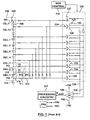
- FIG. 1 the system disclosed by Becker-Irvin (US Patent No. 5,914,606) is shown.
- Measurement points 114 and 116 are connected to the inputs of a voltage divider 111.
- Other measurement points are also connected to respective inputs of other voltage dividers.
- All the divider outputs are connected to a multiplexer 120 that has outputs 129 and 130. These outputs are connected to a differential amplifier A7 .
- the two voltage divider outputs are connected to the multiplexer 120.
- the output of the differential amplifier A7 will be directly proportional to the differential voltage between the pair of points at which the voltage dividers were connected.
- extremely high precision resistors must be used in the voltage dividers. Further, any deviation in the resistance of these resistors will result in improper cell voltage measurement.
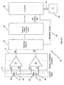
- the fuel cell voltage monitoring system 10 comprises a plurality of differential amplifiers 12 which are connected to a fuel cell stack 13. For simplicity, only two differential amplifiers 14 and 16 and two fuel cells 18 and 20 are shown.
- the fuel cell voltage monitoring system 10 further comprises a switching network 22 , an analog to digital converter (ADC) 24, a controller 26 and a PC 28.
- ADC analog to digital converter
- the fuel cell voltage monitoring system 10 further comprises a calculating means which may be contained within the controller 26 .
- the calculating means may be connected to the output of the controller 26 or the calculating means may be connected to the output of the analog to digital controller 24
- the inputs of the plurality of differential amplifiers 12 are connected to the terminals of the fuel cells in the fuel cell stack 13 and the outputs of the plurality of differential amplifiers 12 are connected to the switching network 22.
- the switching network 22 is also connected to the ADC 24.
- the ADC 24 is connected to the controller 26 which is in turn connected to the PC 28 via an RS 232 cable 30 or any other commercially available PC communication link.
- the calculation means applies a factor to the digital values read from the ADC 24 for providing for more accurate monitoring of the measured cell voltages. The factor is described in more detail further below.
- each differential amplifier has a high common-mode rejection ratio.
- Each differential amplifier preferably is also highly linear
- Each amplifier may have a gain of substantially unity.
- Each amplifier should also be able to reject as high a voltage as possible at each input.
- the input differential is limited by the power supply voltage as is commonly known in the art. Accordingly, the input differential may be limited to a range of +/- 15 V.
- each differential amplifier from the plurality of differential amplifiers 12, is connected to the terminals of a respective fuel cell, in the fuel cell stack 13, whose cell voltage is to be measured.
- differential amplifier 14 is connected across fuel cell 18.
- the two inputs 34 and 36 of the differential amplifier 14 are connected to the anode 38 and the cathode 40 of the fuel cell 18.
- the inputs of a differential amplifier, chosen from the plurality of differential amplifiers 12 do not necessarily have to be connected to the two terminals of one fuel cell. Rather the inputs of the differential amplifier may be connected to any two terminals on the fuel cell stack 13 as desired.
- the input 34 may be connected to the terminal 38 of fuel cell 18 and the input 36 may be connected to the terminal 44 of fuel cell 20.
- each differential amplifier is assumed to be connected to the terminals of a unique fuel cell.
- each differential amplifier from the plurality of differential amplifiers 12, is then connected to the inputs of the switching network 22.
- the output 50 of the differential amplifier 14 and the output 52 of the differential amplifier 16 are connected to the inputs of the switching network 22 (only two inputs are shown for simplicity).
- the switching network 22 may be a multiplexer or the like.
- the switching network 22 only allows the differential voltage measured at two points on the fuel cell stack 13 to be accessed at any one time. This configuration is desirable for reducing the number of components in the fuel cell voltage monitoring system 10 .
- the cell voltages may also be monitored at a high speed so that measuring only one cell voltage at a time is acceptable.
- the differential voltage measured at the two terminals on the fuel cell stack 13 are then sent from the switching network 22 to the ADC 24.
- the ADC 24 converts the measured analog voltages to digital values.
- the ADC 24 may be a 16-bit ADC.
- an ADC with more bits may be used to obtain more accurate digital values.
- the digital values are sent to the controller 26 .
- the controller 26 controls the function of the fuel cell voltage monitoring system 10 .
- the controller 26 controls the operation of the switching network 22 via a switching network control signal 47 and the ADC 24 via an ADC control signal 49.
- the controller 26 controls the switching network 22 to selectively receive the digital values for the cell voltage measured at the two terminals of a specific fuel cell in the fuel cell stack 13.
- the controller 26 directs the switching network 22 to access the voltage measured across each fuel cell in the fuel cell stack 13 in sequential order and reads the corresponding digital values from the ADC 24.
- the measured voltage across any fuel cell can be accessed at any time by appropriately programming the controller 26 .
- the controller is preferably a microprocessor but may also be another control device such as a PLC or the like.
- the controller 26 may include the calculating means 27 for converting the digital values read from the ADC 24 into a measured cell voltage (further explained below).
- the controller 26 is further connected to a PC 28 via an RS232 cable 30 or the like which can be used to provide enhanced data processing to monitor fuel cell performance.
- the cell voltages allow a user to assess the overall condition of an individual fuel cell.
- the cell voltages can be used to determine if there is water accumulation in a cell, or if gases are mixing, etc. How often cell voltages are measured is also important. Cell voltage measurement must be sufficiently fast to report brief, transient conditions on the cells. It is preferred to perform a measurement every 10 ms on every cell, which has been shown to be more than sufficient.
- PC 28 may be in a remote location.
- the plurality of differential amplifiers 12 used in the fuel cell voltage monitoring system 10 may be chosen from any commercially available differential amplifier having a high common-mode rejection ratio. Examples include the Burr-Brown INA 117 differential amplifier or the Analog Devices AD629 differential amplifier. These differential amplifiers can function with a common-mode voltage of up to 200 V and can therefore be connected directly to the cathode and anode of a fuel cell from the fuel cell stack 13 as shown in Figure 2.
- the fuel cell voltage monitoring system 10 requires calibration in order to obtain accurate voltage measurements.
- the common-mode voltage of the inputs of the differential amplifier connected to the single fuel cell increases (the common-mode voltage is simply the average value of the inputs).
- the common-mode voltage of the inputs to the differential amplifier results in a voltage at the output of the differential amplifier which will corrupt the voltage measurement of the differential amplifier.
- the differential amplifier preferably has a high common-mode rejection ratio (CMRR) which is the ratio of the input voltage when the inputs are tied together divided by the output voltage.
- CMRR common-mode rejection ratio
- CMRR common-mode rejection ratio
- values for CMRR are approximately in the range of 70 to 110 dB.
- the DC offset is observed as a finite voltage at the output of the differential amplifier when the inputs of the differential amplifier are connected to ground.
- a voltage error can result in the measurement due to the quantization noise of the ADC 24 .
- the quantization noise can be reduced to an acceptable level by increasing the number of quantization bits in the ADC 24.
- the output of the differential amplifier will deviate from the actual cell voltage of the fuel cell.
- This deviation is referred to as a residual voltage which is a measurement error that cannot be eliminated with common differential amplifier arrangements.
- the residual voltage is proportional to the common-mode voltage of the inputs of the differential amplifier. This is not desirable since as the total number of individual fuel cells increase, the common-mode voltage of the inputs of the differential amplifier increase. Therefore, the deviation in the measured cell voltage for those fuel cells at the top of the fuel cell stack 13 will be large enough to significantly affect the accuracy of the cell voltage measurement.
- the above problem can be overcome if the measured cell voltage of the fuel cell is calculated based on a linear equation which uses the digital values obtained from the voltage measurement of each fuel cell.
- the voltmeter is a high precision voltmeter.
- the cell voltage for each fuel cell measured by a given differential amplifier, can be calculated using the following equation:
- Equation 3 removes the measurement errors to obtain the measured cell voltage for the fuel cell being measured.
- the voltage V OFF represents the DC offset and common mode voltage errors. These errors are removed from the measured value since, based on the principle of superposition, the measured voltage will be the addition of the cell voltage plus these errors.
- the factor V ADC /[V ADC (V A ) - V ADC (V 0 )] is used to correlate the output of the ADC 24 to a meaningful value in Volts.
- This calculation may be carried out by the controller 26. Alternatively, another processing device may be used.
- the calibrated data may then be read by the PC 28 for recording and analysis.
- the switching network 22 By controlling the switching network 22 to access each differential amplifier from the plurality of differential amplifiers 12 in sequence, the cell voltage for each fuel cell in the fuel cell stack 13 can be obtained.
- Figure 3a illustrates the measurement error which occurs when measuring the cell voltage of a fuel cell, from the fuel cell stack 13, if calibration is not used. Assuming there are 102 fuel cells in the fuel cell stack 13 and that each fuel cell operates at 0.75 V (i.e. the cell voltage is 0.75 V), the actual common-mode voltage of the 102 nd fuel cell is 75.75 V (i.e. 0.75*101) as shown in Figure 3a. If a residual voltage error of +50 mV occurs at the output of the differential amplifier 66 connected to the 102 nd fuel cell, the output of the differential amplifier 66 will be 0.8 V (i.e. 0.75+0.05) instead of 0.75 V and it has unity gain. Typically it is expected that voltages can vary in the range up to 5 Volts.
- the measurement error can be eliminated by calibrating the differential amplifier 66 with a calibrator 70 that provides the exact common-mode voltage and cell voltage that would be expected for the 102nd fuel cell which in this example are 75.75 V and 0.75 V respectively.
- a calibrator may be provided for each differential amplifier of the plurality of differential amplifiers 12 .
- one calibrator may be re-used for each differential amplifier from the plurality of differential amplifiers 12 .
- Figure 3b also shows two exemplary placements of a voltmeter 72 for taking accurate voltage measurements at various nodes of the fuel cell voltage monitoring system 10 during calibration with the calibrator 70.
- the calibrator 70 is employed to calibrate the differential amplifier 66 , the common-mode voltage error and the DC offset of the differential amplifier will be obtained.
- the output of the differential amplifier 66 will be the same as it was before calibration was performed (i.e. 0.80 V in the example).
- equation 3 must be used to obtain the actual cell voltage and significantly reduce the residual error.
- the plurality of differential amplifiers 12 may be calibrated before they are used to measure the cell voltages of fuel cells in the fuel cell stack 13 . Therefore, the common-mode voltage error and the DC offset of each differential amplifier can be obtained. Consequently, by calibrating each differential amplifier, the accuracy of the fuel cell voltage monitoring system 10 considerably increases.
- each fuel cell may be assumed to have a cell voltage of 0.75 V. This is an average voltage at which fuel cells operate during normal use. Therefore, during calibration an increment of 0.75 V is used which means the calibrator provides voltages as if the upper terminal of fuel cell 1 is at 0.75 V, the upper terminal of fuel cell 2 is at 1.5 V, the upper terminal of fuel cell 3 is at 2.25 V and the upper terminal of fuel cell 101 is at 76.5 V, as shown in Figure 3b.
- each differential amplifier was calibrated at a common-mode voltage which was close to the actual common-mode voltage at the cell terminals of each fuel cell when each fuel cell was operating under ideal conditions. As a result, the measured cell voltages were close to the actual cell voltage of each fuel cell.
- the calibration method does not completely eliminate the residual error, it significantly reduces the residual error and most notably the common-mode voltage error.
- the common-mode voltage error occurring during the voltage measurement of a given differential amplifier is no longer proportional to the common-mode voltage at the inputs of the differential amplifier.
- the common-mode voltage error is now proportional to the difference between the actual common-mode voltage at the inputs and the assumed common-mode voltage that was used for each fuel cell during calibration. This difference is random and does not increase as the number of fuel cells in the fuel cell stack 13 increase. Therefore, the common-mode voltage error is maintained at a very low level during cell voltage measurement. This is particularly advantageous when measuring the cell voltage of fuel cells in a large fuel cell stack.
- the fuel cell voltage monitoring system 10 uses commonly available components which are inexpensive and do not require any hardware adjustments.
- the present invention also provides for a simple to use and highly precise measurement system.
- the present invention has fewer components which significantly reduces the overall size of the system. Therefore, the fuel cell voltage monitoring system 10 can be easily incorporated into any fuel cell testing device.
- the present invention is intended not only for monitoring the voltages of individual fuel cells, in fuel cell stacks, but also for monitoring the voltages in any kind of multi-cell battery formed by connecting individual cells in series.
- the present invention can also be used to monitor the voltage of a single cell, a battery, a battery bank or an electrolyser.
Landscapes
- Physics & Mathematics (AREA)
- General Physics & Mathematics (AREA)
- Fuel Cell (AREA)
- Measurement Of Current Or Voltage (AREA)
- Secondary Cells (AREA)
Claims (27)
- System (10) zum Überwachen von wenigstens einer Zellspannung einer elektrochemischen Vorrichtung, wobei die Vorrichtung eine Mehrzahl von Zellen (8, 20) aufweist, die in Reihe verbunden sind, wobei jede Zelle zwei Anschlüsse bereitstellt,
wobei das System umfasst:eine Mehrzahl von Differentialverstärkern (12), wobei jeder Differentialverstärker (14, 16) zwei Eingänge (34, 36, 46, 48) und einen Ausgang (50, 52) aufweist, wobei jeder Ausgang (50, 52) der Mehrzahl von Differentialverstärkern (12) eine Gleichtakthochspannung sperrt, wobei die Eingänge von wenigstens einem der Mehrzahl von Differentialverstärkern (12) bei Verwendung mit zwei der Anschlüsse zum Messen einer Differenzspannung desselben verbunden sind,ein Schaltnetzwerk (22), das eine Mehrzahl von Eingängen und einen Ausgang aufweist,einen Analog-Digital-Wandler (24), der einen Eingang aufweist, der mit dem Ausgang des Schaltnetzwerks (22) verbunden ist,und wobei jeder der Mehrzahl von Eingängen des Schaltnetzwerks (22) mit dem Ausgang (50, 52) von einem der Differentialverstärker (14, 16) verbunden ist, der Analog-Digital-Wandler (24) ausgelegt ist, digitale Werte bereitzustellen, die die Differenzspannung angeben, die durch den wenigstens einen der Mehrzahl von Differentialverstärkern (12) gemessen wird,eine Steuereinrichtung (26), die mit dem Schaltnetzwerk (22) und dem Analog-Digital-Wandler (24) verbunden ist, um den Betrieb des Schaltnetzwerks (22) und des Analog-Digital-Wandlers (24) zu steuern und um die digitalen Werte zu empfangen, wobei das System gekennzeichnet ist durch:eine Berechnungseinrichtung, die mit dem Ausgang von entweder dem Analog-Digital-Wandler (24) oder der Steuereinrichtung (26) verbunden ist, die eine Einrichtung zum Empfangen der digitalen Werte und zum Anwenden eines Faktors auf die digitalen Werte umfasst, um Gleichtaktspannungsfehler von diesen zu entfernen. - System (10) nach Anspruch 1, dadurch gekennzeichnet, dass jeder Differentialverstärker (14, 16) ausgelegt ist, eine Gleichtaktspannung von 200 V zu sperren.
- System (10) nach Anspruch 1, dadurch gekennzeichnet, dass die Steuereinrichtung (26) die Berechnungseinrichtung bereitstellt.
- System (10) nach Anspruch 1, dadurch gekennzeichnet, dass die Steuereinrichtung (26) einen Mikroprozessor umfasst.
- System (10) nach Anspruch 1, dadurch gekennzeichnet, dass das System (10) ferner einen Computer (28) umfasst und die Steuereinrichtung (26) mit dem Computer (28) verbunden ist.
- System (10) nach Anspruch 1, dadurch gekennzeichnet, dass die Berechnungseinrichtung eine lineare Gleichung anwendet, um Fehler aus den digitalen Werten zu entfernen, wobei die lineare Gleichung durch eine Kalibrierung von wenigstens zwei Eingangsspannungen definiert ist.
- System (10) nach Anspruch 6, dadurch gekennzeichnet, dass das System (10) wenigstens eine Kalibriereinrichtung (70) umfasst, die mit einem der Mehrzahl von Differentialverstärkern (12) verbindbar ist, um den Faktor zu ermitteln.
- System (10) nach Anspruch 7, dadurch gekennzeichnet, dass die wenigstens eine Kalibiereinrichtung ausgelegt ist, zwei Kalibrierspannungen den Eingängen (50, 52) des einen der Mehrzahl von Differentialverstärkern (12) bereit zu stellen, wobei die zwei Kalibrierspannungen um ein konstantes Spannungsinkrement voneinander versetzt sind, um eine Differenzspannung und eine Gleichtaktspannung an den Anschlüssen von einer der Mehrzahl von Zellen (18, 20) zu emulieren.
- System (10) nach Anspruch 8, dadurch gekennzeichnet, dass das konstante Spannungsinkrement in dem Bereich von 0,5 V bis 1 V gewählt ist.
- System (10) nach Anspruch 9, dadurch gekennzeichnet, dass das konstante Spannungsinkrement 0,75 V beträgt.
- System (10) nach Anspruch 8, dadurch gekennzeichnet, dass die Berechnungseinrichtung den Faktor auf die digitalen Werte anwendet, die aus den Spannungswerten abgetastet werden, die von einem ausgewählten Differentialverstärkern (14, 16) unter der Mehrzahl von Differentialverstärkern (12) gemessen werden, gemäß
- Verfahren zum Überwachen wenigstens einer Zellspannung für eine Mehrzahl von elektrochemischen Zellen (18, 20), die in Reihe verbunden sind, wobei die elektrochemischen Zellen (18, 20) zwei Anschlüsse aufweisen, wobei das Verfahren die Schritte umfasst:(a) Verbinden von zwei der Anschlüsse der Mehrzahl von elektrochemischen Zellen (18, 20) mit den Eingängen (34, 36, 46, 48) eines Differentialverstärkers (14, 16), wobei der Differentialverstärker (14, 16) zwei Eingänge (34, 36, 46, 48) und einen Ausgang (50, 52) aufweist, wobei die zwei Anschlüsse eine erste und eine zweite Spannung bereitstellen, die eine Gleichtaktspannung aufweisen,(b) Sperren der Gleichtaktspannung in dem Differentialverstärker (14, 16), um eine Differenzspannung zwischen den zwei Anschlüssen zu messen,(c) Umwandeln der Differenzspannung von einem analogen in einen digitalen Wert, und gekennzeichnet durch den Schritt:(d) Anwenden eines Faktors auf den digitalen Wert, um einen Gleichtaktspannungsfehler aus der Differenzspannung zu entfernen.
- Verfahren nach Anspruch 12, dadurch gekennzeichnet, dass der Schritt (a) ferner umfasst, eine Mehrzahl von Differentialverstärkern (12) bereitzustellen, wobei jeder Differentialverstärker (14, 16) zwei Eingänge (34, 36, 46, 48) und einen Ausgang (50, 52) aufweist, und zusätzliche Paare von Anschlüssen der Mehrzahl von elektrochemischen Zellen (18, 20) mit der Mehrzahl von Differentialverstärkern (12) zu verbinden, wobei jedes der Paare von Anschlüssen mit Eingängen (34, 36, 46, 48) von einem der Mehrzahl der Differentialverstärker (14, 16) verbunden ist, wobei die zusätzlichen Paare von Anschlüssen jeweils eine Gleichtaktspannung aufweisen, und die Schritte (b), (c) und (d) für jeden der Differentialverstärker (14, 16) durchgeführt werden.
- Verfahren nach Anspruch 13, dadurch gekennzeichnet, dass das Verfahren ferner umfasst, die Ausgänge (50, 52) der Differentialverstärker (14, 16) über ein Schaltnetzwerk (22) mit einem Analog-Digital-Wandler (24) zu verbinden, wobei das Schaltnetzwerk (22) verwendet wird, um den Ausgang (50, 52) von einem der Differentialverstärker (14, 16) zu dem Analog-Digital-Wandler (24) für eine Analog-Digital-Wandlung der Differenzspannung an dem Ausgang des einen Differentialverstärkers (14, 16) zu schalten.
- Verfahren nach Anspruch 14, dadurch gekennzeichnet, dass das Verfahren ferner umfasst, eine Steuereinrichtung (26) bereitzustellen, um das Schaltnetzwerk (22) und den Analog-Digital-Wandler (24) zu steuern.
- Verfahren nach Anspruch 15, dadurch gekennzeichnet, dass das Verfahren ferner umfasst, die Steuereinrichtung (26) als Mikroprozessor bereitzustellen.
- Verfahren nach Anspruch 12, dadurch gekennzeichnet, dass Schritt (d) umfasst, eine lineare Gleichung zum Entfernen von Fehlern aus den digitalen Werten anzuwenden, wobei die lineare Gleichung durch eine Kalibrierung von wenigstens zwei Eingangsspannungen definiert wird.
- Verfahren nach Anspruch 12 oder 13, dadurch gekennzeichnet, dass das Verfahren ferner den Schritt umfasst:(e) bekannte erste und zweite Kalibrierspannungen von einer Kalibriereinrichtung den Eingängen jedes Differentialverstärkers (14, 16) bereitzustellen und die Spannung an dem Ausgang desselben (50, 52) zu messen, um den Faktor zu ermitteln.
- Verfahren nach Anspruch 18, dadurch gekennzeichnet, dass das Verfahren umfasst, den Schritt (e) für jeden Differentialverstärker zu bewirken gemäß den Schritten:(f) Verbinden des Ausgangs (50, 52) des Differentialverstärkers (14, 16) mit einem Analog-Digital-Wandler,(g) Anlegen einer Spannung VA, die auf den ersten und zweiten Kalibrierspannungen basiert, über den Eingängen (34, 36, 46, 48) des Differentialverstärkers (14, 16) und Messen von VA,(h) Messen der Ausgabe (VADC (VA)) des Analog-Digital-Wandlers (24), wenn VA an die Eingänge des Differentialverstärkers (14, 16) differentiell angelegt wird,(i) Messen der Ausgabe (VADC (V0)) des Analog-Digital-Wandlers (24), wenn die Eingänge (34, 36, 46, 48) des Differentialverstärkers (14, 16) mit Masse verbunden sind, und(j) Messen der Offset-Gleichspannung (VOFF) an dem Ausgang (50, 52) des Differentialverstärkers (14, 16), wenn die Eingänge (34, 36, 46, 48) des Differentialverstärkers (14, 16) auf Masse gelegt werden.
- Verfahren nach Anspruch 19, dadurch gekennzeichnet, dass das Verfahren ferner umfasst, eine kalibrierte gemessene Zellspannung (VR) zu berechnen, um die wenigstens eine Zellspannung zu überwachen, wobei die gemessene Zellspannung (VR) auf einer gemessenen Spannung basiert, die aus der Ausgabe (VADC) des Analog-Digital-Wandlers (24) erhalten wird, wenn die Eingänge (34, 36, 46, 48) des Differentialverstärkers (14, 16) über zwei der Anschlüsse angeschlossen sind, wobei die Berechnung ausgeführt wird gemäß:
- Verfahren nach Anspruch 13, dadurch gekennzeichnet, dass das Verfahren ferner umfasst, Differenzialverstärker (14, 16) bereitzustellen, die eine Gleichtaktspannung von 200 V sperren können.
- Verfahren nach Anspruch 18, dadurch gekennzeichnet, dass das Verfahren ferner umfasst, die zweite Kalibrierspannung mit einem konstanten Spannungsinkrement hinsichtlich der ersten Kalibrierspannung bereitzustellen, um die Differenzspannung und die Gleichtaktspannung zu emulieren, die unter normalen Betriebsbedingungen an den Anschlüssen einer Zelle der Mehrzahl von elektrochemischen Zellen (18, 20) erwartet werden würden.
- Verfahren nach Anspruch 21, dadurch gekennzeichnet, dass das Verfahren ferner umfasst, das konstante Spannungsinkrement in dem Bereich von 0,5 V bis 1 V auszuwählen.
- Verfahren nach Anspruch 23, dadurch gekennzeichnet, dass das Verfahren ferner umfasst, das konstante Spannungsinkrement so auszuwählen, dass es 0,75 V beträgt.
- Verfahren nach Anspruch 12, dadurch gekennzeichnet, dass das Verfahren ferner umfasst, die Zellspannung jeder der elektrochemischen Zellen (18, 20) nacheinander zu überwachen.
- Verfahren nach Anspruch 12, dadurch gekennzeichnet, dass das Verfahren ferner umfasst, die Zellspannung von irgendeiner der elektrochemischen Zellen (18, 20) zu irgendeinem Zeitpunkt zu überwachen.
- Verfahren nach Anspruch 12, dadurch gekennzeichnet, dass das Verfahren ferner umfasst, das Verfahren anzuwenden, um Brennstoffzellenspannungen zu messen.
Applications Claiming Priority (3)
| Application Number | Priority Date | Filing Date | Title |
|---|---|---|---|
| US09/865,562 US20020180447A1 (en) | 2001-05-29 | 2001-05-29 | Fuel cell voltage monitoring system and the method thereof |
| US865562 | 2001-05-29 | ||
| PCT/CA2002/000791 WO2002097460A2 (en) | 2001-05-29 | 2002-05-29 | Fuel cell voltage monitoring |
Publications (2)
| Publication Number | Publication Date |
|---|---|
| EP1390771A2 EP1390771A2 (de) | 2004-02-25 |
| EP1390771B1 true EP1390771B1 (de) | 2005-11-30 |
Family
ID=25345784
Family Applications (1)
| Application Number | Title | Priority Date | Filing Date |
|---|---|---|---|
| EP02729728A Expired - Lifetime EP1390771B1 (de) | 2001-05-29 | 2002-05-29 | Überwachung der brennstoffzellenspannung |
Country Status (8)
| Country | Link |
|---|---|
| US (1) | US20020180447A1 (de) |
| EP (1) | EP1390771B1 (de) |
| CN (1) | CN100350261C (de) |
| AT (1) | ATE311609T1 (de) |
| AU (1) | AU2002302268A1 (de) |
| CA (1) | CA2448866C (de) |
| DE (1) | DE60207707T2 (de) |
| WO (1) | WO2002097460A2 (de) |
Families Citing this family (34)
| Publication number | Priority date | Publication date | Assignee | Title |
|---|---|---|---|---|
| US6816797B2 (en) * | 2000-09-29 | 2004-11-09 | Hydrogenics Corporation | System and method for measuring fuel cell voltage and high frequency resistance |
| US20040002791A1 (en) * | 2002-06-27 | 2004-01-01 | Ki-Chun Lee | Fuel cell monitoring system |
| US7425832B2 (en) * | 2003-02-04 | 2008-09-16 | Hydrogenics Corporation | System and method for measuring internal resistance of electrochemical devices |
| CA2467263A1 (en) * | 2003-05-14 | 2004-11-14 | Hydrogenics Corporation | Method, system and apparatus for testing electrochemical cells |
| EP1501146A3 (de) * | 2003-07-24 | 2007-04-25 | Matsushita Electric Industrial Co., Ltd. | Brennstoffzellensystem, Verfahren zum Betrieb einer Brennstoffzelle, Programm und Speichermedium |
| US20050110464A1 (en) * | 2003-11-25 | 2005-05-26 | Baker Howard S. | Fuel cell voltage monitoring system |
| EP1706753A1 (de) * | 2004-01-20 | 2006-10-04 | Hydrogenics Corporation | Brennstoffzellen-spannungsüberwachungssystem und diesbezügliche elektrische verbinder |
| US8278876B2 (en) * | 2005-03-07 | 2012-10-02 | O2Micro, Inc. | Battery pack current monitoring |
| WO2006096958A1 (en) * | 2005-03-17 | 2006-09-21 | Hydrogenics Corporation | Multiplexer and system for supplying current to an electrochemical cell stack |
| CN100464195C (zh) * | 2005-03-30 | 2009-02-25 | 上海神力科技有限公司 | 一种安全准确的燃料电池电压监测装置 |
| JP2006302629A (ja) * | 2005-04-20 | 2006-11-02 | Hitachi Ltd | 燃料電池モジュールおよび燃料電池モジュールを用いた発電システム |
| GB0604802D0 (en) * | 2006-03-09 | 2006-04-19 | Dfc Energy Ltd | Improvements in and relating to fuel cells |
| US8372553B2 (en) * | 2006-04-04 | 2013-02-12 | GM Global Technology Operations LLC | Fuel cell voltage unit for detecting a failed plate connection |
| KR100813247B1 (ko) * | 2006-10-17 | 2008-03-13 | 삼성에스디아이 주식회사 | 연료전지 시스템 및 그 운영방법 |
| US8237447B2 (en) * | 2007-05-11 | 2012-08-07 | Panasonic Ev Energy Co., Ltd. | Apparatus for detecting state of storage device |
| CN101363879B (zh) * | 2007-08-09 | 2013-03-20 | 比亚迪股份有限公司 | 电平极性转化装置和电压采样装置及电压采样方法 |
| JP2010199054A (ja) * | 2009-01-27 | 2010-09-09 | Toyota Motor Corp | 燃料電池用電圧監視システム |
| JP5533175B2 (ja) * | 2009-05-20 | 2014-06-25 | 日産自動車株式会社 | 組電池監視装置 |
| US8564277B2 (en) | 2009-08-31 | 2013-10-22 | Maxim Integrated Products, Inc. | System for and method of virtual simultaneous sampling with a single ADC core |
| CN101806866B (zh) * | 2010-04-07 | 2013-02-13 | 大连交通大学 | 一种燃料电池电堆的单体电池电压测量电路 |
| US9017889B2 (en) * | 2011-06-28 | 2015-04-28 | GM Global Technology Operations LLC | Frame sequence for a cell voltage measurement system with a low probability of natural occurrence |
| CN102508035B (zh) * | 2011-11-01 | 2014-11-12 | 武汉理工大学 | 一种燃料电池交流阻抗在线测试系统与测控方法 |
| US9157963B2 (en) * | 2012-08-10 | 2015-10-13 | O2Micro Inc. | Method and system for calibrating battery pack voltage based on common-mode calibration parameter and differential-mode calibration parameter |
| KR20160069077A (ko) * | 2014-12-05 | 2016-06-16 | 현대오트론 주식회사 | 배터리 모니터링 방법 및 이를 실행하는 장치 |
| CN110247085A (zh) * | 2019-03-29 | 2019-09-17 | 上海楞次新能源汽车科技有限公司 | 一种通道可配置的燃料电池单体电压检测装置 |
| CN109917181A (zh) * | 2019-04-08 | 2019-06-21 | 上海大学 | 一种电压采集系统 |
| US11374244B2 (en) * | 2019-10-31 | 2022-06-28 | Hyundai Mobis Co., Ltd. | Apparatus and method for measuring voltage and average power of fuel cell |
| US11664513B2 (en) * | 2019-11-08 | 2023-05-30 | Hyundai Mobis Co., Ltd. | System and method for sensing fuel cell of vehicle |
| US11428719B2 (en) | 2020-01-10 | 2022-08-30 | Analog Devices International Unlimited Company | Electrical signal measurement using subdivision |
| CN113162153A (zh) * | 2021-03-26 | 2021-07-23 | 上海闻泰信息技术有限公司 | 电池组件、电池组件的控制方法和终端 |
| EP4202452B1 (de) * | 2021-12-21 | 2025-11-12 | dSPACE GmbH | Vorrichtung und verfahren zum kalibrieren eines batterieemulators |
| US12461182B2 (en) | 2021-12-21 | 2025-11-04 | Dspace Gmbh | Apparatus and method for calibrating a battery emulator |
| US12596153B2 (en) * | 2023-02-10 | 2026-04-07 | Relyion Energy Inc. | Voltage transducer |
| CN116338480A (zh) * | 2023-04-20 | 2023-06-27 | 西安迅湃快速充电技术有限公司 | 一种消除共模电压误差的电池电压采样系统及补偿方法 |
Family Cites Families (9)
| Publication number | Priority date | Publication date | Assignee | Title |
|---|---|---|---|---|
| JPH01160367A (ja) * | 1987-12-17 | 1989-06-23 | Toshiba Electric Equip Corp | インバータ |
| CA2018639A1 (en) * | 1990-06-08 | 1991-12-08 | James D. Blair | Method and apparatus for comparing fuel cell voltage |
| CN2226310Y (zh) * | 1994-12-26 | 1996-05-01 | 大连市旅顺电力电子设备有限公司 | 检测蓄电池组电参数的电压信号采集器 |
| US5608307A (en) * | 1994-12-29 | 1997-03-04 | Motorola, Inc. | Apparatus for controlling excess recharge current applied to a battery |
| US5914606A (en) * | 1996-10-10 | 1999-06-22 | Becker-Irvin; Craig H. | Battery cell voltage monitor and method |
| JP3863262B2 (ja) * | 1997-09-30 | 2006-12-27 | 松下電器産業株式会社 | 電池電圧測定装置 |
| JP3870577B2 (ja) * | 1998-09-14 | 2007-01-17 | 株式会社デンソー | 組電池のばらつき判定方法及びバッテリ装置 |
| US6313750B1 (en) * | 1999-08-23 | 2001-11-06 | Plug Power Inc. | Measuring cell voltages of a fuel cell stack |
| US6140820A (en) * | 1999-12-27 | 2000-10-31 | Plug Power Inc. | Measuring cell voltages of a fuel cell stack |
-
2001
- 2001-05-29 US US09/865,562 patent/US20020180447A1/en not_active Abandoned
-
2002
- 2002-05-29 WO PCT/CA2002/000791 patent/WO2002097460A2/en not_active Ceased
- 2002-05-29 DE DE60207707T patent/DE60207707T2/de not_active Expired - Fee Related
- 2002-05-29 CA CA002448866A patent/CA2448866C/en not_active Expired - Fee Related
- 2002-05-29 AU AU2002302268A patent/AU2002302268A1/en not_active Abandoned
- 2002-05-29 CN CNB028149017A patent/CN100350261C/zh not_active Expired - Fee Related
- 2002-05-29 AT AT02729728T patent/ATE311609T1/de not_active IP Right Cessation
- 2002-05-29 EP EP02729728A patent/EP1390771B1/de not_active Expired - Lifetime
Also Published As
| Publication number | Publication date |
|---|---|
| CA2448866A1 (en) | 2002-12-05 |
| DE60207707T2 (de) | 2006-07-27 |
| WO2002097460A2 (en) | 2002-12-05 |
| CN1535384A (zh) | 2004-10-06 |
| AU2002302268A1 (en) | 2002-12-09 |
| CN100350261C (zh) | 2007-11-21 |
| WO2002097460A3 (en) | 2003-02-20 |
| EP1390771A2 (de) | 2004-02-25 |
| ATE311609T1 (de) | 2005-12-15 |
| US20020180447A1 (en) | 2002-12-05 |
| DE60207707D1 (de) | 2006-01-05 |
| CA2448866C (en) | 2008-02-05 |
Similar Documents
| Publication | Publication Date | Title |
|---|---|---|
| EP1390771B1 (de) | Überwachung der brennstoffzellenspannung | |
| EP1611449B1 (de) | Vorrichtung und verfahren zur messung der brennstoffzellenspannung und des hochfrequenzwiderstandes | |
| US6208147B1 (en) | Method of and apparatus for measuring battery capacity by impedance spectrum analysis | |
| EP1918729B1 (de) | Diagnose- und Prognose-Verfahren für eine Lithiumionenbatterie | |
| EP1391962A1 (de) | Spannungsmessschaltung eines batteriepacks | |
| KR20040010528A (ko) | 연료전지 임피던스의 측정장치 | |
| US20040220752A1 (en) | System and method for measuring internal resistance of electrochemical devices | |
| KR20000003044A (ko) | 펄스전류의 전압 응답신호를 이용한 전지용량 측정방법 및 측정장치 | |
| CN112068019B (zh) | 一种平板型sofc电流密度分布式端板测试结构及测试方法 | |
| JP7511572B2 (ja) | インピーダンス標準器 | |
| CN114865117A (zh) | 锂离子电池电极嵌锂量检测方法、装置及电池管理系统 | |
| US20050110464A1 (en) | Fuel cell voltage monitoring system | |
| CN118671436A (zh) | 燃料电池的平均功率测量装置及方法、电压测量装置 | |
| EP4542246A1 (de) | Batteriediagnoseverfahren und batteriediagnosevorrichtung sowie batteriesystem mit bereitstellung des verfahrens | |
| CN113782786A (zh) | 一种燃料电池电堆氢渗电流原位检测方法与装置 | |
| CN117805713A (zh) | 一种电流传感器测试系统及方法 | |
| US20060051628A1 (en) | Diagnostic method for an electrochemical fuel cell and fuel cell components | |
| CN112394286A (zh) | 液流电池的soc的测试方法、系统及电池储能系统 | |
| US20260029482A1 (en) | Electrochemical method for state of health estimation | |
| CN224152564U (zh) | 一种电堆的交流阻抗巡检测试系统 | |
| US12413084B2 (en) | Asymmetric device for diagnosis, for charging and/or for discharging of electric batteries and conductors for said device | |
| HK1070137A (en) | Fuel cell voltage monitoring system and the method thereof | |
| JP2007214072A (ja) | 燃料電池スタックのセル電圧測定装置 | |
| CN120370184A (zh) | 一种电池内阻的解耦方法 | |
| CN120121901A (zh) | 一种电堆的交流阻抗巡检测试系统及测试方法 |
Legal Events
| Date | Code | Title | Description |
|---|---|---|---|
| PUAI | Public reference made under article 153(3) epc to a published international application that has entered the european phase |
Free format text: ORIGINAL CODE: 0009012 |
|
| 17P | Request for examination filed |
Effective date: 20031030 |
|
| AK | Designated contracting states |
Kind code of ref document: A2 Designated state(s): AT BE CH CY DE DK ES FI FR GB GR IE IT LI LU MC NL PT SE TR |
|
| AX | Request for extension of the european patent |
Extension state: AL LT LV MK RO SI |
|
| 17Q | First examination report despatched |
Effective date: 20040324 |
|
| GRAP | Despatch of communication of intention to grant a patent |
Free format text: ORIGINAL CODE: EPIDOSNIGR1 |
|
| GRAS | Grant fee paid |
Free format text: ORIGINAL CODE: EPIDOSNIGR3 |
|
| GRAA | (expected) grant |
Free format text: ORIGINAL CODE: 0009210 |
|
| AK | Designated contracting states |
Kind code of ref document: B1 Designated state(s): AT BE CH CY DE DK ES FI FR GB GR IE IT LI LU MC NL PT SE TR |
|
| PG25 | Lapsed in a contracting state [announced via postgrant information from national office to epo] |
Ref country code: IT Free format text: LAPSE BECAUSE OF FAILURE TO SUBMIT A TRANSLATION OF THE DESCRIPTION OR TO PAY THE FEE WITHIN THE PRESCRIBED TIME-LIMIT;WARNING: LAPSES OF ITALIAN PATENTS WITH EFFECTIVE DATE BEFORE 2007 MAY HAVE OCCURRED AT ANY TIME BEFORE 2007. THE CORRECT EFFECTIVE DATE MAY BE DIFFERENT FROM THE ONE RECORDED. Effective date: 20051130 Ref country code: NL Free format text: LAPSE BECAUSE OF FAILURE TO SUBMIT A TRANSLATION OF THE DESCRIPTION OR TO PAY THE FEE WITHIN THE PRESCRIBED TIME-LIMIT Effective date: 20051130 Ref country code: LI Free format text: LAPSE BECAUSE OF FAILURE TO SUBMIT A TRANSLATION OF THE DESCRIPTION OR TO PAY THE FEE WITHIN THE PRESCRIBED TIME-LIMIT Effective date: 20051130 Ref country code: AT Free format text: LAPSE BECAUSE OF FAILURE TO SUBMIT A TRANSLATION OF THE DESCRIPTION OR TO PAY THE FEE WITHIN THE PRESCRIBED TIME-LIMIT Effective date: 20051130 Ref country code: FI Free format text: LAPSE BECAUSE OF FAILURE TO SUBMIT A TRANSLATION OF THE DESCRIPTION OR TO PAY THE FEE WITHIN THE PRESCRIBED TIME-LIMIT Effective date: 20051130 Ref country code: BE Free format text: LAPSE BECAUSE OF FAILURE TO SUBMIT A TRANSLATION OF THE DESCRIPTION OR TO PAY THE FEE WITHIN THE PRESCRIBED TIME-LIMIT Effective date: 20051130 Ref country code: CH Free format text: LAPSE BECAUSE OF FAILURE TO SUBMIT A TRANSLATION OF THE DESCRIPTION OR TO PAY THE FEE WITHIN THE PRESCRIBED TIME-LIMIT Effective date: 20051130 |
|
| REG | Reference to a national code |
Ref country code: CH Ref legal event code: EP Ref country code: GB Ref legal event code: FG4D |
|
| REG | Reference to a national code |
Ref country code: IE Ref legal event code: FG4D |
|
| REF | Corresponds to: |
Ref document number: 60207707 Country of ref document: DE Date of ref document: 20060105 Kind code of ref document: P |
|
| PG25 | Lapsed in a contracting state [announced via postgrant information from national office to epo] |
Ref country code: GR Free format text: LAPSE BECAUSE OF FAILURE TO SUBMIT A TRANSLATION OF THE DESCRIPTION OR TO PAY THE FEE WITHIN THE PRESCRIBED TIME-LIMIT Effective date: 20060228 Ref country code: DK Free format text: LAPSE BECAUSE OF FAILURE TO SUBMIT A TRANSLATION OF THE DESCRIPTION OR TO PAY THE FEE WITHIN THE PRESCRIBED TIME-LIMIT Effective date: 20060228 Ref country code: SE Free format text: LAPSE BECAUSE OF FAILURE TO SUBMIT A TRANSLATION OF THE DESCRIPTION OR TO PAY THE FEE WITHIN THE PRESCRIBED TIME-LIMIT Effective date: 20060228 |
|
| PG25 | Lapsed in a contracting state [announced via postgrant information from national office to epo] |
Ref country code: ES Free format text: LAPSE BECAUSE OF FAILURE TO SUBMIT A TRANSLATION OF THE DESCRIPTION OR TO PAY THE FEE WITHIN THE PRESCRIBED TIME-LIMIT Effective date: 20060313 |
|
| PG25 | Lapsed in a contracting state [announced via postgrant information from national office to epo] |
Ref country code: PT Free format text: LAPSE BECAUSE OF FAILURE TO SUBMIT A TRANSLATION OF THE DESCRIPTION OR TO PAY THE FEE WITHIN THE PRESCRIBED TIME-LIMIT Effective date: 20060502 |
|
| PG25 | Lapsed in a contracting state [announced via postgrant information from national office to epo] |
Ref country code: IE Free format text: LAPSE BECAUSE OF NON-PAYMENT OF DUE FEES Effective date: 20060529 |
|
| PG25 | Lapsed in a contracting state [announced via postgrant information from national office to epo] |
Ref country code: MC Free format text: LAPSE BECAUSE OF NON-PAYMENT OF DUE FEES Effective date: 20060531 |
|
| NLV1 | Nl: lapsed or annulled due to failure to fulfill the requirements of art. 29p and 29m of the patents act | ||
| REG | Reference to a national code |
Ref country code: CH Ref legal event code: PL |
|
| ET | Fr: translation filed | ||
| PLBE | No opposition filed within time limit |
Free format text: ORIGINAL CODE: 0009261 |
|
| STAA | Information on the status of an ep patent application or granted ep patent |
Free format text: STATUS: NO OPPOSITION FILED WITHIN TIME LIMIT |
|
| 26N | No opposition filed |
Effective date: 20060831 |
|
| REG | Reference to a national code |
Ref country code: IE Ref legal event code: MM4A |
|
| PGFP | Annual fee paid to national office [announced via postgrant information from national office to epo] |
Ref country code: DE Payment date: 20070524 Year of fee payment: 6 |
|
| PGFP | Annual fee paid to national office [announced via postgrant information from national office to epo] |
Ref country code: GB Payment date: 20070521 Year of fee payment: 6 |
|
| PGFP | Annual fee paid to national office [announced via postgrant information from national office to epo] |
Ref country code: FR Payment date: 20070430 Year of fee payment: 6 |
|
| PG25 | Lapsed in a contracting state [announced via postgrant information from national office to epo] |
Ref country code: LU Free format text: LAPSE BECAUSE OF NON-PAYMENT OF DUE FEES Effective date: 20060529 Ref country code: TR Free format text: LAPSE BECAUSE OF FAILURE TO SUBMIT A TRANSLATION OF THE DESCRIPTION OR TO PAY THE FEE WITHIN THE PRESCRIBED TIME-LIMIT Effective date: 20051130 |
|
| PG25 | Lapsed in a contracting state [announced via postgrant information from national office to epo] |
Ref country code: CY Free format text: LAPSE BECAUSE OF FAILURE TO SUBMIT A TRANSLATION OF THE DESCRIPTION OR TO PAY THE FEE WITHIN THE PRESCRIBED TIME-LIMIT Effective date: 20051130 |
|
| GBPC | Gb: european patent ceased through non-payment of renewal fee |
Effective date: 20080529 |
|
| REG | Reference to a national code |
Ref country code: FR Ref legal event code: ST Effective date: 20090119 |
|
| PG25 | Lapsed in a contracting state [announced via postgrant information from national office to epo] |
Ref country code: FR Free format text: LAPSE BECAUSE OF NON-PAYMENT OF DUE FEES Effective date: 20080602 Ref country code: DE Free format text: LAPSE BECAUSE OF NON-PAYMENT OF DUE FEES Effective date: 20081202 |
|
| PG25 | Lapsed in a contracting state [announced via postgrant information from national office to epo] |
Ref country code: GB Free format text: LAPSE BECAUSE OF NON-PAYMENT OF DUE FEES Effective date: 20080529 |