EP1390780B1 - Systeme de controle a rayons x - Google Patents
Systeme de controle a rayons x Download PDFInfo
- Publication number
- EP1390780B1 EP1390780B1 EP02763892A EP02763892A EP1390780B1 EP 1390780 B1 EP1390780 B1 EP 1390780B1 EP 02763892 A EP02763892 A EP 02763892A EP 02763892 A EP02763892 A EP 02763892A EP 1390780 B1 EP1390780 B1 EP 1390780B1
- Authority
- EP
- European Patent Office
- Prior art keywords
- ray
- item
- inspection
- inspection system
- dimension
- Prior art date
- Legal status (The legal status is an assumption and is not a legal conclusion. Google has not performed a legal analysis and makes no representation as to the accuracy of the status listed.)
- Expired - Lifetime
Links
- 238000007689 inspection Methods 0.000 title claims abstract description 225
- 238000000034 method Methods 0.000 claims abstract description 68
- 230000005855 radiation Effects 0.000 claims abstract description 65
- 230000008569 process Effects 0.000 claims abstract description 25
- 238000001514 detection method Methods 0.000 claims abstract description 18
- 238000012545 processing Methods 0.000 claims description 17
- 239000000463 material Substances 0.000 claims description 10
- 229910021417 amorphous silicon Inorganic materials 0.000 claims description 7
- 230000001427 coherent effect Effects 0.000 claims description 6
- 238000005259 measurement Methods 0.000 claims description 6
- 230000004044 response Effects 0.000 claims description 4
- 238000002441 X-ray diffraction Methods 0.000 claims 2
- 238000002591 computed tomography Methods 0.000 description 30
- 230000009977 dual effect Effects 0.000 description 8
- 239000002360 explosive Substances 0.000 description 8
- 238000004458 analytical method Methods 0.000 description 4
- 239000002131 composite material Substances 0.000 description 4
- 230000008901 benefit Effects 0.000 description 3
- 238000010586 diagram Methods 0.000 description 3
- 239000003814 drug Substances 0.000 description 3
- 229940079593 drug Drugs 0.000 description 3
- 238000013519 translation Methods 0.000 description 3
- 230000004075 alteration Effects 0.000 description 2
- 238000004891 communication Methods 0.000 description 2
- 230000000694 effects Effects 0.000 description 2
- 238000005516 engineering process Methods 0.000 description 2
- 239000002184 metal Substances 0.000 description 2
- 238000012986 modification Methods 0.000 description 2
- 230000004048 modification Effects 0.000 description 2
- 239000010409 thin film Substances 0.000 description 2
- 230000009466 transformation Effects 0.000 description 2
- 238000012795 verification Methods 0.000 description 2
- PXFBZOLANLWPMH-UHFFFAOYSA-N 16-Epiaffinine Natural products C1C(C2=CC=CC=C2N2)=C2C(=O)CC2C(=CC)CN(C)C1C2CO PXFBZOLANLWPMH-UHFFFAOYSA-N 0.000 description 1
- 238000010521 absorption reaction Methods 0.000 description 1
- 230000002730 additional effect Effects 0.000 description 1
- 230000002238 attenuated effect Effects 0.000 description 1
- 230000008878 coupling Effects 0.000 description 1
- 238000010168 coupling process Methods 0.000 description 1
- 238000005859 coupling reaction Methods 0.000 description 1
- 230000007423 decrease Effects 0.000 description 1
- RZILCCPWPBTYDO-UHFFFAOYSA-N fluometuron Chemical compound CN(C)C(=O)NC1=CC=CC(C(F)(F)F)=C1 RZILCCPWPBTYDO-UHFFFAOYSA-N 0.000 description 1
- 239000011521 glass Substances 0.000 description 1
- 238000003384 imaging method Methods 0.000 description 1
- 230000006872 improvement Effects 0.000 description 1
- 238000004949 mass spectrometry Methods 0.000 description 1
- 238000000691 measurement method Methods 0.000 description 1
- -1 money Substances 0.000 description 1
- 238000009659 non-destructive testing Methods 0.000 description 1
- 239000000523 sample Substances 0.000 description 1
- 238000012216 screening Methods 0.000 description 1
- 230000035945 sensitivity Effects 0.000 description 1
- 238000001228 spectrum Methods 0.000 description 1
- 238000003325 tomography Methods 0.000 description 1
- 238000012546 transfer Methods 0.000 description 1
Images






Classifications
-
- G—PHYSICS
- G01—MEASURING; TESTING
- G01V—GEOPHYSICS; GRAVITATIONAL MEASUREMENTS; DETECTING MASSES OR OBJECTS; TAGS
- G01V5/00—Prospecting or detecting by the use of ionising radiation, e.g. of natural or induced radioactivity
- G01V5/20—Detecting prohibited goods, e.g. weapons, explosives, hazardous substances, contraband or smuggled objects
- G01V5/22—Active interrogation, i.e. by irradiating objects or goods using external radiation sources, e.g. using gamma rays or cosmic rays
- G01V5/222—Active interrogation, i.e. by irradiating objects or goods using external radiation sources, e.g. using gamma rays or cosmic rays measuring scattered radiation
-
- G—PHYSICS
- G01—MEASURING; TESTING
- G01V—GEOPHYSICS; GRAVITATIONAL MEASUREMENTS; DETECTING MASSES OR OBJECTS; TAGS
- G01V5/00—Prospecting or detecting by the use of ionising radiation, e.g. of natural or induced radioactivity
- G01V5/20—Detecting prohibited goods, e.g. weapons, explosives, hazardous substances, contraband or smuggled objects
- G01V5/22—Active interrogation, i.e. by irradiating objects or goods using external radiation sources, e.g. using gamma rays or cosmic rays
- G01V5/224—Multiple energy techniques using one type of radiation, e.g. X-rays of different energies
-
- G—PHYSICS
- G01—MEASURING; TESTING
- G01V—GEOPHYSICS; GRAVITATIONAL MEASUREMENTS; DETECTING MASSES OR OBJECTS; TAGS
- G01V5/00—Prospecting or detecting by the use of ionising radiation, e.g. of natural or induced radioactivity
- G01V5/20—Detecting prohibited goods, e.g. weapons, explosives, hazardous substances, contraband or smuggled objects
- G01V5/271—Detecting prohibited goods, e.g. weapons, explosives, hazardous substances, contraband or smuggled objects using a network, e.g. a remote expert, accessing remote data or the like
Definitions
- the invention relates to X-ray inspection systems for examination of items such as baggage or packages. More specifically, the invention relates to an X-ray inspection system and method, that utilizes X-ray radiation modified by the item under inspection to detect, for example, weapons, drugs, explosives, or other contraband.
- a level one system may process baggage rapidly, such as at a targeted rate of approximately 1500 bags per hour.
- the level one system may be located at a first inspection station and may inspect all baggage.
- the level one system may rapidly scan baggage using some detection methodology, to eliminate non-suspicious baggage. This methodology may determine a property of materials within the baggage, such as, for example, mass density, or effective atomic number, or may employ Compton X-ray scatter, ion mass spectroscopy, or other detection techniques.
- the number of bags that are not cleared (that are rejected) by a level one system may range from 10% - 50% of the total number of bags, depending on the detection methodology and threat thresholds used in the particular system.
- the bags rejected by the level one system may be automatically sent to a level two area where an operator may visually inspect an X-ray image of the bag.
- the operator may search the image of the bag for characteristic objects, such as weapons, wires, explosives, etc., and may attempt to determine whether a suspicious object within the bag may be cleared based on its obvious shape.
- the operator at a level two station may clear most, but not all of the rejected bags.
- the remaining baggage may be on the order of, for example, 0.1% - 0.5% of the initial stream, and may be sent to a level three inspection station.
- the bag may be inspected with a slower inspection device, than a level one system, that may use a different detection methodology to the level one system.
- a prescan step such as prescanning with a line scanner, is used to expedite the operation of the CT object detector by identifying those regions of the luggage which should be CT scanned and those regions which may be disregarded.
- the object detection system includes a workstation where an operator can look at the accumulated CT cross-sectional images on a monitor.
- the workstation is preferably provided with a standard Ethernet network connection that may be used to transmit the images to a remote display station, or to an expert operator who can sequentially look at images from any number of inspection systems.
- Peschmann further discloses that once CT scanning data has been accumulated, target objects within the CT image data are defined as connected regions with physical density within a preset range.
- a verification step may optionally be employed to increase the confidence of the identification of the target objects.
- This verification step may include, for example, comparing the shape of the object against a list of characteristics corresponding to the target object, using dual energy CT data for comparison against known dual energy signatures for target objects or for innocuous objections, or by using texture information.
- a device that may be used as a level three detection device may be a multi-probe tomography system such as that described in US Patent No. 5,642,393, herein incorporated by reference.
- a level three device may tend to clear less than half of the objects it inspects.
- approximately 0.05% - 0.25% of the baggage may need to be sent to a level four area.
- a level four area may be defined as reconciliation of the bag with the owner; which may often be difficult. If reconciliation is not possible, the bag may be confiscated and additional problems may arise, such as, termination of the flight that the bag was to be on.
- the present invention as set forth in claim 1, is directed toward an X-ray inspection system comprising an X-ray source located at an inspection region that exposes an item under inspection to X-ray radiation and an X-ray detector located at the inspection region that detects X-ray radiation as modified by the item under inspection, and that is constructed and arranged to be movable in a first dimension and a second dimension.
- the system further comprises a controller coupled to each of the X-ray source, the X-ray detector, that controls movement of the X-ray detector in the first and second dimensions, and a processor coupled to the controller that is configured to receive detection information from the X-ray detector, to process the detection information, and to provide processed information.
- the system is characterized in that the X-ray source is constructed and arranged to be movable in any of the first dimension, the second dimension and a third dimension, and the controller is also configured to control movement of the X-ray source and the X-ray detector, independently of each other, in any of collinear directions and different directions, to provide a plurality of X-ray views of the item under inspection at varying examination angles of the X-ray radiation.
- the controller is additionally configured to control movement of the X-ray source in the third dimension so as to provide varying levels of zoom of the processed information to the operator interface.
- the system also comprises an operator interface, coupled to the controller and the processor, that is configured to receive instructions from an operator input, to provide the instructions to the controller to control movement of any of the X-ray source, the X-ray detector and the conveyor, and that is configured to receive the processed information and present the processed information to an operator.
- an operator interface coupled to the controller and the processor, that is configured to receive instructions from an operator input, to provide the instructions to the controller to control movement of any of the X-ray source, the X-ray detector and the conveyor, and that is configured to receive the processed information and present the processed information to an operator.
- the processor is additionally configured to process the plurality of X-ray views to create a tiled scout view of the item under inspection and to provide the tiled scout view to the operator interface.
- the processor is further configured to receive information about the item under inspection from a remote inspection device, and to locate a region of interest in the item under inspection based on the information received.
- a further embodiment is directed toward a high resolution X-ray inspection system comprising a high resolution X-ray source located at an inspection region that exposes an item under inspection to X-ray radiation.
- the high resolution source has a focal spot size that is less than approximately 100 ⁇ m, and is constructed and arranged to be movable in any of the first dimension, a second dimension, and a third dimension.
- the system further comprises an X-ray detector located at the inspection region that detects X-ray radiation as modified by the item under inspection, and that is constructed and arranged to be movable in the first dimension and the second dimension, and a controller.
- the controller is coupled to each of the X-ray source, the X-ray detector, and controls movement of the X-ray source in the first and second dimensions, and movement of the X-ray detector in the first and second dimensions.
- the system further comprises a processor that is configured to receive detection information from the X-ray detector, to process the detection information, and to provide processed information.
- Another embodiment is directed toward a method of inspecting an item with an X-ray system, the method comprising acts of exposing an item to X-ray radiation from an X-ray source, detecting the X-ray radiation, as modified by the item, with an X-ray detector, processing information provided by the X-ray detector to provide processed information, and providing the processed information.
- the method is characterized in that the method comprises acts of moving the X-ray source in any of a first dimension and a second dimension to expose the item to X-ray radiation at a plurality of positions, and moving the X-ray detector, independently of the X-ray source, in any of the first dimension and the second dimension to detect the X-ray radiation at a plurality of positions, so as to provide the processed information at a plurality of examination angles.
- Another embodiment comprises an operator interface that is coupled to the controller and the processor, and is configured to receive instructions from an operator input, to provide the instructions to the controller to control the movement of any of the X-ray source, the X-ray detector and the conveyor, and is configured to present the processed information to an operator.
- the method further comprises an act of moving the X-ray source in a third dimension so as to provide varying levels of zoom of the processed information to the operator interface.
- the act of processing the information comprises creating a tiled scout view of the item from X-ray images obtained at each the plurality of positions, and wherein the act of providing the processed information comprises providing the tiled scout view to the operator interface.
- the method further comprising acts of receiving, from a remote inspection device, information about the item and locating a region of interest in the item based on the information received.
- Another embodiment is directed to a method of inspecting an item with an X-ray system, comprises acts of exposing an item to X-ray radiation from an X-ray source, detecting the X-ray radiation as modified by the item with an X-ray detector, processing information provided by the X-ray detector to provide processed information, and providing the processed information.
- the method further comprises acts of moving the X-ray source in any of a first dimension and a second dimension to expose the item to X-ray radiation at a plurality of positions, moving the X-ray detector in any of the first dimension and the second dimension to detect the X-ray radiation at a plurality of positions, and moving the X-ray source in a third dimension so as to provide varying levels of zoom of the processed information.
- Another embodiment is directed to a method of inspecting an item with an X-ray system, comprising acts of exposing an item to X-ray radiation from an X-ray source having a focal spot size of less than approximately 100 ⁇ m, detecting the X-ray radiation as modified by the item with an X-ray detector, processing information provided by the X-ray detector to provide processed information.
- the method further comprises acts of moving the X-ray source in any of a first dimension and a second dimension to expose the item to X-ray radiation at a plurality of positions, and moving the X-ray detector in any of a first dimension and a second dimension to detect the X-ray radiation at a plurality of positions.
- the X-ray inspection system disclosed herein can be used to detect different types of contraband (for example, weapons, drugs, money, plastic explosives, or other types of explosives) that may be present in items such as baggage or packages, by detecting X-ray radiation transmitted through and/or scattered from the item.
- contraband for example, weapons, drugs, money, plastic explosives, or other types of explosives
- the X-ray inspection system is not so limited, and may be used in a number of ways, such as, non-destructive testing of parts, and the like.
- a multi-level inspection system 10 as is known in the related art. It includes a first inspection device 12, which may be, for example, a level one or level two X-ray inspection system, which examines items being transported on a conveyor 14.
- a first inspection device 12 which examines an item 16 and determines that the item is free of any questionable regions of interest that could contain, for example, contraband such as drugs or explosives
- the item for example, items 16a, 16b
- the item director 20 in communication with the inspection device 12, to proceed further along conveyor 14.
- the item director 20 may direct item 16c along conveyor 14b to an X-ray inspection system 18, which may be, for example, a level three X-ray inspection system, such as the X-ray inspection system disclosed infra.
- the X-ray inspection system 18 may be coupled to an operator interface 22 located at remote location 32, where an operator can oversee the inspection process, evaluate data detected and processed by the X-ray inspection system 18, and direct operation of the X-ray inspection system 18. It is to be appreciated that although the X-ray inspection system may be interfaced for operator control, the X-ray inspection system may also be configured to automatically evaluate and determine whether region of interest in an item under inspection is cause for concern.
- FIG. 2 is a schematic view of one embodiment of an X-ray inspection system 24 that may be used, for example, as a level three X-ray inspection device as described above.
- An item under inspection 16 may be transported on a conveyor 14 to an inspection region 26.
- the conveyor 14 may be halted so that the item under inspection 16 is stationary during the examination process, or it may continue moving.
- the movement of the item by conveyor 14, in response to a control signal on line 25, may be under operator control, such as via operator interface 50, or automatic control by controller 40.
- An X-ray detector 30 may be located at the inspection region 26 to detect X-ray radiation either transmitted through, or scattered by, the item under inspection 16.
- the X-ray detector 30 may be located at an opposite side of the conveyor 14 from the X-ray source 28, to detect attenuation of the X-ray radiation transmitted by the X-ray source 28 through the item under inspection 16.
- the conveyor 14, the X-ray source 28, and the X-ray detector 30 may be coupled to controller 40, which may independently control movement of the X-ray source 28, by a control signal on line 27, in any and all of a first (x), second (y), and third (z) dimension, may independently control movement of the X-ray detector 30, by a control signal on line 29, in any and all of the first (x) and second (y) dimensions, and may independently control movement of the conveyor 14 in the first (x) dimension in response to a control signal on line 25.
- the controller 40 may also control the times at which the X-ray source 28 emits X-ray radiation.
- the controller 40 may further be configured to receive detection information from the X-ray detector 30 on line 35, to process the detection information, and to provide processed information.
- system of Fig. 2 can comprise an embodiment wherein the detector 30 may be also movable in the Z dimension. It is also contemplated that the system of Fig. 2 may further comprise a device, that may be responsive to the processor, that rotates the item under inspection to provide up to and included a 360° rotation of the item under inspection.
- the controller 40 may be coupled to an operator interface 50 which may be configured to receive instructions from an operator, to allow the operator to, via the controller 40 and the operator interface 50, control movement of any and all of the X-ray source 28, the X-ray detector 30, and the conveyor 14.
- the controller 40 may also present the processed information, which may be in the form of, for example, an X-ray image to the operator interface 50 to be accessed by an operator.
- the controller 40 and the operator interface 50 may further be coupled to a network connection 34 that allows information, such as, the processed information to be transmitted to, and received from, a remote location.
- a remote inspection device 104 may be located at the remote location.
- the network connection can be any communication network, such as, an intranet within an airport facility and the internet
- the remote inspection device 104 can be any remote device such as an operator interface remote from the system 24 but within the airport facility or an operator interface at another airport facility.
- the controller 14 may comprise any of a central processing unit 42, a data interface 44, a control interface 46, and a display interface 48.
- the operator interface 50 may comprise operator controls 52 and a display 54.
- the central processing unit 42 may be coupled to the operator controls 52 so that by manipulating the operator controls 52 an operator can provide input signals to the central processing unit 42.
- the central processing unit 42 may also be coupled to the control interface 46, which in turn may be coupled to actuators (not illustrated) associated with the X-ray source 28, the X-ray detector 30, and the conveyor 14.
- Control signals may be sent from the central processing unit 42 through the control interface 46 to the actuators via control signals on lines 27, 29 and 25 to respectively control movement of the X-ray source 28, the X-ray detector 30, and the conveyor 14.
- the central processing unit 42 may also be coupled to a data interface 44.
- the data interface 44 may be configured to receive detection information from the X-ray detector 30 on line 35, and to transfer it to the central processing unit 42 where it may be processed before being transferred to the operator interface 50.
- the display interface 48 may also be coupled to the central processing unit 42 and may be configured to receive processed information from the central processing unit 42 and provide the processed information in a suitable format to the operator interface 50, for example in the form of an X-ray image.
- the X-ray image can be displayed on the display 54, for access by an operator.
- system of Fig. 2 is illustrated as comprising a conveyor 14, a corresponding actuator (not illustrated), and is coupled to controller 40, the system of Fig. 2 can be provided without a conveyor and can be configured to be adapted to an existing conveyor device.
- the system of Fig. 2 can be configured to work with and interface to the existing conveyor system.
- the X-ray source 28 may be a high resolution, micro-focus X-ray source having a focal spot size 56 less than approximately 100 ⁇ m.
- the high resolution X-ray source may have a focal spot size 56 that is less than approximately 20 ⁇ m.
- the high resolution X-ray source may have a focal spot size less than approximately 12 ⁇ m.
- the high resolution X-ray source may be used in conjunction with a high resolution X-ray detector to provide a high resolution X-ray inspection system.
- FIGS. 3a and 3b illustrate two advantages and characteristics of a micro-focus X-ray source 28 as compared to a conventional X-ray source 36.
- FIG. 3 a illustrates an effect on clarity of an X-ray image using a high-resolution X-ray source 28 that has a small focal spot 56 (for example, less than 100 ⁇ m), as opposed to a conventional X-ray source 36 that has a focal spot 58 size of approximately 300 ⁇ m.
- the magnification and resolution of an X-ray image 38 provided by an X-ray source may be determined, at least in part, by the focal spot size of the X-ray source. As shown in FIG.
- a smaller focal spot size 56 can result in a higher resolution, clearer image 38 of an item 16 than can be obtained when the item 16 is exposed by a conventional X-ray source 36 having a larger focal spot size 58, where the sources are located the same distance away from the item 16.
- the larger size of the focal spot 58 of the conventional X-ray source 36 may cause some cross-over of the X-ray radiation, resulting in an indistinct image 60.
- FIG. 3b illustrates a second characteristic and advantage of a micro-focus X-ray source 28.
- the micro-focus X-ray source 28 may have a shorter focal length 62 than the focal length 64 of the conventional X-ray source 36. Because of this shorter focal length 62, two distances may be reduced, allowing, for example, for a more compact instrument package. First, for an image of the same magnification, distance 66 from the micro-focus X-ray source 28 to image 38 may be reduced compared with the distance 68 from the conventional source 36 to the image 70. Second, the shorter focal length 62 may allow the item under inspection 16 to be placed closer to the X-ray source 28.
- the microfocus X-ray source 28 may provide a greater magnitude of X-ray radiation to the item 16 for an image with the same magnification as the conventional source 36, and may thereby produce a sharper, clearer, and higher resolution X-ray image. Because of the characteristics of the micro-focus X-ray source 28 discussed above, the microfocus X-ray source 28 can also provide greater magnification images of the item 16. As shown in FIG. 3b the micro-focus X-ray source 28 can provide an image 72 that may be of significantly greater magnification than image 70 produced by the conventional source 36 at the same distance from the source.
- the X-ray source 28 may be a single energy X-ray source.
- the X-ray source may be a dual energy X-ray source.
- a dual-energy X-ray source may produce high energy X-ray radiation and low energy X-ray radiation.
- a dual-energy X-ray source, X-ray inspection system and methodology using the dual energy X-ray source, is disclosed in U.S. Patent No. 5,319,547 (the '547 patent), which is incorporated herein by reference. It is to be appreciated that the dual-energy X-ray source and system of the '547 patent can be modified as described herein to provide an X-ray system and methodology at dual energy levels.
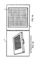
- FIGS. 4a and 4b illustrate, in perspective and plan view, an embodiment of the X-ray detector 30 that may be used in the X-ray system (see FIG. 2).
- the X-ray detector 30 may be a radiation image detector such as a PerkinElmer RID 1640.
- the X-ray detector 30 may be a flat panel sensor 74 fabricated using thin film technology including amorphous silicon on glass panels.
- the panel sensor 74 may be a square image sensing photodiode array with 1024 x 1024 pixels.
- Each pixel 76 of the X-ray detector array may consist of a light sensing photodiode and a switching thin film transistor formed with the amorphous silicon technology.
- the amorphous silicon photodiodes are sensitive to visible light.
- This light-sensitive photodiode array may be coupled to a scintillation material which responds to X-rays.
- the X-rays When striking the scintillator, the X-rays are converted to visible light which may be detected by the photodiodes and transformed into electrical signals.
- the sensitivity of amorphous silicon photodiodes peaks in the green light spectrum, which is well matched to scintillators made of a material, such as, Csl or Gd 2 O 2 S:Tb, which is commercially available as a LANEX ® fine scintillator from, for example, Kodak.
- the amorphous silicon panel itself is substantially immune to damage from large doses of X-rays.
- This feature makes the X-ray detector array suitable for use in an inspection system, such as a baggage inspection system at an airport, where a large number of items are inspected at a high throughput rate, and the detector is thus continually exposed to X-ray radiation. It is also suitable for use in combination with a dual energy X-ray source, such as disclosed above, where the source may frequently emit high-energy and low energy X-ray radiation.
- FIG. 5 illustrates an embodiment of the controller 40 and operator interface 50 (see FIG. 2).
- operator interface 50 may comprise a joystick 78 coupled the controller 40 via lines 84.
- the joystick 78 may ultimately be coupled to controller 40 through computer 80 via line 83.
- the controller 40 may also be coupled to linear actuators 82a-c and may effect movement of any one of the X-ray source, the X-ray detector, and the conveyor in any of the first, second and third dimensions.
- controller 40 By manipulating the joystick 78, the operator may provide the control signals over lines 84 to controller 40, which can activate the linear actuators 82a-c to move the conveyor to move the item under inspection in the x dimension, to move the X-ray source in any of the x, y and z dimensions, and/or to move the X-ray detector in the x and y dimensions to the desired position. It is to be appreciated that although there is illustrated one actuator for each dimension (x, y, z) to control movement of each of the X-ray source, the X-ray detector and the conveyor, there may be provided more than one separate actuator for each dimension and for each device to be moved by the actuators.
- the controller 40 may receive information from computer 80 operating under a process executed by the computer 80, to automatically move the X-ray source, the X-ray detector, and/or the conveyor to move the item under inspection, without necessary intervention by an operator.
- FIG. 6 illustrates an example movement of either one or both of the X-ray source 28 and X-ray detector 30 to create a tiled scout view that can be provided by the system of FIG. 2.
- the controller 40 may move any of the X-ray source 28, the X-ray detector 30, and the conveyor 14, to a plurality of positions in order to create the tiled scout view 86 of the item under inspection.
- FIG. 6 there is illustrated an example of movement of the X-ray source and the X-ray detector, which may be moved collinearly to a number of sequential positions, where an image is recorded at each position.
- the conveyor and thus the item, is held stationary during the automatic inspection process and the tiled scout view 86 may comprise an array of 30 measurements comprising five tiles in the cross-belt direction and six tiles in the down-belt direction.
- Each tile 88 may represent a 1024x1024 image, which may cover a 0.2m x 0.2m area on the belt.
- the controller 40 may move the X-ray source 28 and the X-ray detector 30 independently of each other to provide a plurality of X-ray views of the item under inspection at varying examination angles of the X-ray radiation that are provided by independent location of the X-ray source and the X-ray detector.
- the X-ray source and the X-ray detector can be moved independently to measure the item under inspection at numerous angles and along a plurality of planes or slices created by the independent locations of the source and detector.
- FIG. 7 illustrates an example of movement of any or both of the X-ray source and/or the X-ray detector of FIG. 2, when the item under inspection is moving, to create a tiled scout view. It is to be appreciated that in one embodiment during the inspection process, the conveyor 14 may continue to move the item under inspection through the region of inspection, such as, at a reduced speed, and that this movement of the item may be accounted for in the tiling process.
- FIG. 7 illustrates a plurality of measurements that can be used to create the tiled scout view if the item is moving during the inspection process.
- a tiled row of a composite image can be constructed by taking a first 2/3 of a first frame 90 and a last 2/3 of a last frame 94 to form the left and right edges of a portion of the tiled scout view, and taking a middle third of each intermediate frame 92 to create the interior of each tile 88 of the portion of the tiled scout view.
- This procedure may yield a tiled scout view that is five tiles in the cross-belt direction and six tiles in the down-belt direction.
- the resulting composite image may be 6144 x 5120 pixels in size.
- This composite image may be down-sampled by six in both directions to yield a composite tiled scout view that may be 1008 x 850 pixels.
- FIG. 8 illustrates an example of an operator interface 96 according to one embodiment.
- the tiled scout view may be provided by the controller to the operator interface for possible analysis by an operator and may be, for example, displayed by the operator interface on computer 80 (see figure 5), or on display 54 (see figure 2).
- the tiled scout view may be continuously displayed in one area 98 of the display, while an image in a main display area 100 may be modified by an operator. For example, at the start of an inspection process, the initial tiled scout view may be displayed in the main display area 100. If an operator, or the controller, locates a region of interest in the tiled scout view, the operator may select this region of interest for further inspection.
- the region of interest may then be displayed in the main display area 100, and the tiled scout view may be displayed in area 98.
- the operator may further direct the controller, such as via the operator interface, to move the X-ray source in the third dimension (z-dimension) closer to, or further away from, the item under inspection 16 (see FIG. 2) to provide a zoomed image of the region of interest.
- the zoomed image may be obtained by moving the X-ray source closer to the item under inspection.
- the operator may then inspect the region of interest in greater detail.
- the operator may also bring the tiled scout view back to the main display area 100 by manipulating an appropriate control on the operator interface.
- Various statistics and information regarding the system may also be displayed in a display area 102.
- display area 102 may display information such as online/offline status of screening devices, operator workload, number of bags screened per hour, percentage of bags rejected, etc.
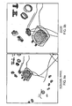
- FIGS. 9a and 9b there are illustrated examples of X-ray images that may be provided by the X-ray inspection system of FIG. 2.
- FIG. 9a illustrates an example image of a region of interest within an item under inspection. Referring to FIG. 9a, it is illustrated that a suspect device containing wires has been detected.
- Fig 9b illustrates an example of a zoomed image of the item of FIG. 9a, that may be obtained by moving the X-ray source in the third dimension closer to the item. The zoomed image may provide more detail of materials within the item.
- the controller 40 may receive information about the item under inspection from a remote inspection device 104 (see FIG. 2).
- the remote inspection device 104 may be, for example, a level one or level two threat detection system, or an inspection device at a location different from the location of the X-ray inspection system.
- the controller 40 may be configured to automatically position any or all of the X-ray source, the X-ray detector, and the conveyor to position the item under inspection, so as to inspect a region of interest in the item under inspection based on the information received from the remote inspection device 104, including a region of interest previously identified by the remote inspection device 104.
- the information received may be an X-ray image of the item under inspection obtained by the remote inspection device showing a region of interest in the item, and the controller may provide the image received from the remote inspection device as well as the tiled scout view of the item under inspection to the operator interface 50.
- an operator may compare the tiled scout view with an image from the remote inspection device 104 to locate the region of interest in the item under inspection.
- the controller 40 may also be configured to automatically compare the image obtained from the remote inspection device with the tiled scout view to locate the region of interest.
- the item may be imaged at, for example, a first level (step 110).
- the item may then be conveyed to, for example, a second level (step 112) at which may be located the X-ray inspection system 24 (see FIG. 2), and imaged by the X-ray inspection system (step 114).
- This imaging may produce a tiled scout view of the item.
- the controller may locate a region of interest in the image provided by the first level inspection device (step 116). However, the item may have been translated, rotated, or otherwise shifted in orientation during its conveyance from the first level to the second level.
- the X-ray inspection system may use fiduciary data regarding the item in order to reconcile the image of the item provided by the remote inspection device with the tiled scout view of the item.
- fiduciary data may be utilized to account for rotation of the item in a plane of the conveyor, translation of the item, and magnification in the z-dimension by the system.
- the controller may locate at least two fiducial points within the image from the remote inspection device. It is to be understood that the term "fiducial points" are so called because they are points that remain “faithful” from one image of the item to the next, even if the item shifts in orientation between the two images.
- fiducial points may be a metal button, a metal zipper clasp, a wheel, or another small, dense object. At least two fiducial points may be used to resolve rotation and translation in the x-dimension of the item, and three fiducial points may be used to additionally resolve translation of the item in the y-dimension. However, additional fiducial points such as up to twenty fiducial points, may be located in the image and used to ensure that at least some of these fiducial points may be located in the tiled scout view (some fiducial points that may be located in the image may be obscured in the tiled scout view).
- the controller may define a geometric relationship, such as, for example, a distance between the fiducial points (step 118).
- the controller may locate the corresponding two fiducial points in the tiled scout view of the item, and may resolve the fiducial point relationships between the image and the tiled scout view (step 124) to reconcile the image provided by the remote inspection with the tiled scout view, and to locate the region of interest in the tiled scout view.
- steps 116 and 118 may be performed by a remote processor associated with the remote inspection device.
- the remote processor may create a list of fiducial data, such as, for example, the relationships between the fiducial points in the image of the item (step 120), and may transmit the data to the X-ray inspection system disclosed herein (step 122).
- the controller may position the X-ray source, the X-ray detector, and/or the conveyor to position the item and to inspect the region of interest (step 126).
- an operator may position any of the item (the conveyor), the X-ray source and X-ray detector to view multiple regions of interest in the item (step 128).
- the controller may be configured to automatically position any of the X-ray source, the X-ray detector, and the conveyor to position the item and to view multiple regions of interest in the item, based on information received from the remote inspection device.
- a region of interest located in an item under inspection may be subjected to a further, more detailed inspection by the system of Fig. 2 in addition to the X-ray measurement.
- This further inspection may include one or more additional X-ray inspections, such as, a coherent X-ray scatter analysis or a Computed Laminography scan.
- the controller 40 (see FIG. 2) may also be configured to automatically position the X-ray source 28, the X-ray detector 30 and the conveyor 14, and therefore the item under inspection 16, as needed for the further inspection. This additional inspection may be done, for example, if an operator cannot clear an item based on the X-ray image alone.
- this embodiment of the system may further comprise an energy sensitive detector 106a that detects X-ray radiation in a predetermined energy window that is scattered by the item under inspection.
- an energy sensitive detector 106a that detects X-ray radiation in a predetermined energy window that is scattered by the item under inspection. It is to be appreciated that some components of Fig. 11 are illustrated with the same reference numerals as the corresponding components of the system of Fig. 2, and that the operation of the components has already been discussed infra with respect to Fig. 2 and is therefore not repeated in this discussion of the embodiment of Fig. 11.
- the energy sensitive detector 106a may be configured to provide the coherent scatter information to the controller 40 via line 31, which may process the information and perform coherent X-ray scatter analysis.
- a coherent X-ray scatter analysis may measure additional properties of materials of the region of interest within the item under inspection, which may aid an operator or the system in making a decision on whether or not the item under inspection can be cleared.
- the X-ray scatter detector 106a may be disposed in the inspection region 26 so as to detect X-ray radiation back-scattered by the item.
- the X-ray scatter detector 106a may be disposed at the inspection region 26 at a different location so as to detect X-ray radiation scattered by the item under inspection at a selected angle.
- the X-ray inspection system may comprise two or more X-ray scatter detectors 106a, 106b disposed at different locations at the inspection region 26, so as to detect X-ray radiation scattered at different angles by the item under inspection.
- the X-ray source 28 and the X-ray detector 30 of the X-ray inspection system 24 may be adapted to perform a Computed Laminography scan of the region of interest.
- the controller 40 may be configured to suitably position and control movement of any of the X-ray source 28, the X-ray detector 30 and the conveyor 14 to move the item 16, to perform the Computed Laminography scan.
- Computed Laminography is a measurement technique and process for measuring detailed X-ray images of one or more predetermined planar sections of an item under inspection, while not focussing on images of other planes with the measurement.
- a Computed Laminography scan may provide a better image of the item and remove clutter either underlying or overlying a region of interest, thereby enabling an operator to more clearly see the region of interest in the image. It is to be appreciated that the system of Fig. 11 can be adopted to perform a computed Laminography scan by, for example, using the process of U.S. Patent No. 5,490,218 herein incorporated by reference.
- the X-ray inspection system 24, 24' may also be used in conjunction with a computed tomographic (CT) scanner 108 (See Fig. 11).
- CT scanner 108 may be used to provide information about the three-dimensional spatial configuration of materials within the item under inspection, but typically takes a long time to process each CT scan, and is therefore not ideally suited to many applications that require efficient, real-time scanning of the item (such as, baggage inspection at airports). Coupling the CT scanner 108 with the X-ray inspection system 24 may increase the efficiency of the item inspection.
- the X-ray inspection system 24 may be used to identify a region of interest in the item under inspection that warrants a further, more detailed inspection by the CT scanner 108.
- Positional information regarding the location of the region of interest in the item may be provided by the controller 40 of the X-ray inspection system 24 to the CT scanner 108, which may then perform a CT scan on the identified region of interest. Since this region of interest is typically significantly smaller than the whole item under inspection, the time required for the CT scan may be reduced, thereby making the combined X-ray inspection system 24, 24' and CT scanner feasible for use in the above-mentioned types of applications.
- the item under inspection may also be transferred to a remote location for further inspection, should additional equipment be required for the inspection.
- additional equipment should not be necessary since the X-ray inspection system is intended to provide detailed images that are sufficient to detect any contraband under most circumstances, and is also configured to perform most additional scanning (if necessary) at the same location.
- the X-ray inspection system 24, 24' may include a network connection 34 (see FIG. 2 and FIG. 11) that couples the system to a network such as, for example, the Internet, a local area network, or a public telephone network.
- the controller may be configured to provide the processed information, such as X-ray images, to a remote operator interface 104 (see FIG. 1), or to receive instructions from the remote operator interface 104, via the network 34.
- This network allows, for example, remote operators to view data or images obtained by the system, to oversee or direct the inspection process, or to identify items that need be inspected when they arrive at the remote location. Examples of remote operators may include a local police bomb squad, or a customs official at an airport destination of the item under inspection.
Landscapes
- Physics & Mathematics (AREA)
- High Energy & Nuclear Physics (AREA)
- Life Sciences & Earth Sciences (AREA)
- General Life Sciences & Earth Sciences (AREA)
- General Physics & Mathematics (AREA)
- Geophysics (AREA)
- Analysing Materials By The Use Of Radiation (AREA)
- Medicines Containing Antibodies Or Antigens For Use As Internal Diagnostic Agents (AREA)
- Eye Examination Apparatus (AREA)
Claims (45)
- Système de contrôle à rayons X (24) qui inspecte un élément sous contrôle (16) situé dans une zone de contrôle (26), le système comprenant :une source de rayons X (28) située au niveau de la zone de contrôle (26) qui expose l'élément sous contrôle (16) aux rayons X ;un détecteur de rayons X (30) situé sur la zone de contrôle (26) qui détecte les rayons X tels que modifiés par l'élément sous contrôle (16), et qui est conçu et installé de manière à pouvoir être déplacé dans une première dimension et une deuxième dimension ;un contrôleur (40) couplé à la source de rayons X (28) et au détecteur de rayons X (30), qui contrôle les déplacements du détecteur de rayons X (30) dans les première et deuxième dimensions ; etun processeur (42) couplé au contrôleur qui est configuré pour recevoir des informations de détection provenant du détecteur de rayons X (30), pour traiter les informations de détection, et pour fournir des informations traitées ;caractérisé en ce quela source de rayons X (28) est conçue et installée de manière à pouvoir être déplacée dans l'une quelconque des première, deuxième et une troisième dimensions ;le contrôleur (40) est configuré pour contrôler les déplacements de la source de rayons X (28) dans les première et deuxième dimensions ; etle contrôleur (40) est également configuré pour contrôler les déplacements de la source de rayons X (28) et du détecteur de rayons X (28) indépendamment l'une de l'autre dans l'une quelconque des directions colinéaires et différentes directions pour fournir une pluralité de vues aux rayons X de l'élément sous contrôle (16) sous différents angles d'inspection aux rayons X.
- Système de contrôle à rayons X (24) selon la revendication 1, dans lequel le contrôleur (40) est également configuré pour contrôler les déplacements de la source de rayons X (28) dans la troisième dimension de manière à proposer différents niveaux de zoom des informations traitées.
- Système de contrôle à rayons X (24) selon la revendication 1 ou 2, comprenant en outre une interface opérateur (50), couplée au contrôleur (40) et au processeur (42), qui est configuré pour recevoir des instructions provenant d'une entrée opérateur, pour transmettre les instructions au contrôleur (40) pour contrôler le déplacement de la source de rayons X (28) ou du détecteur de rayons X (30), et qui est configuré pour recevoir et présenter les informations traitées à un opérateur.
- Système de contrôle à rayons X (24) selon la revendication 1, dans lequel le processeur (42) est configuré pour traiter la pluralité de vues aux rayons X pour créer un scanogramme en mosaïque de l'élément sous contrôle (16).
- Système de contrôle à rayons X (24) selon la revendication 4, dans lequel le processeur (42) est configuré pour créer le scanogramme en mosaïque d'un élément entier sous contrôle (16).
- Système de contrôle à rayons X (24) selon la revendication 4, dans lequel le processeur (42) est également configuré pour recevoir des informations sur l'élément sous contrôle (16) provenant d'un dispositif de contrôle distant (104) et localiser une zone intéressante de l'élément sous contrôle (16) à partir des informations reçues.
- Système de contrôle à rayons X (24) selon la revendication 6, dans lequel les informations sur l'élément sous contrôle (16) comprennent une image, et le processeur (42) est également configuré pour comparer au moins deux points conventionnels dans l'image avec au moins deux points conventionnels correspondants dans le scanogramme en mosaïque et pour aligner l'image et le scanogramme en mosaïque pour localiser la zone intéressante dans le scanogramme en mosaïque.
- Système de contrôle à rayons X (24) selon la revendication 6, dans lequel le contrôleur (40) est également configuré pour positionner automatiquement la source de rayons X (28) et le détecteur de rayons X (30) pour un contrôle supplémentaire de la zone intéressante dans l'élément sous contrôle (16), en réponse aux informations reçues par le processeur (42).
- Système de contrôle à rayons X (24) selon la revendication 8, comprenant en outre un détecteur sensible à l'énergie (106a) couplé au processeur (42), qui détecte les rayons X dans une fenêtre d'énergie prédéterminée qui sont dispersés par l'élément sous contrôle (16), et dans lequel le processeur (42) réalise une analyse cohérente des rayons X dispersés de l'élément sous contrôle (16).
- Système de contrôle à rayons X (24) selon la revendication 1, comprenant en outre un convoyeur (14) conçu et installé pour déplacer l'élément sous contrôle (16) dans la première dimension vers la zone de contrôle (26), et dans lequel le contrôleur (40) est également configuré pour contrôler les déplacements du convoyeur (14) dans la première dimension.
- Système de contrôle à rayons X (24) selon la revendication 10, comprenant en outre un actionneur linéaire (82a) réceptif au contrôleur (40) et couplé au convoyeur (14) qui déplace le convoyeur (14) dans la première dimension.
- Système de contrôle à rayons X (24) selon la revendication 1, dans lequel la source de rayons X (28) est conçue et installée pour exposer l'élément sous contrôle (16) à un faisceau de rayons X en forme de cône.
- Système de contrôle à rayons X (24) selon la revendication 12, dans lequel la source de rayons X (28) comporte une tâche focale (56) d'une taille inférieure à 100 µm, de manière à fournir un système de contrôle à rayons X de haute résolution.
- Système de contrôle à rayons X (24) selon la revendication 1, dans lequel le détecteur de rayons X (30) comprend une matrice de détecteur de rayons X au silicium amorphe bidimensionnel.
- Système de contrôle à rayons X (24) selon la revendication 2, comprenant en outre une pluralité d'actionneurs linéaires (82a, 82b, 82c) réceptive au contrôleur (40) et couplée à la source de rayons X (28) et au détecteur de rayons X (30), qui déplacent la source de rayons X (28) dans l'une quelconque des première, deuxième et troisième dimensions, et déplacent le détecteur de rayons X (30) dans l'une quelconque des première et deuxième dimensions.
- Système de contrôle à rayons X (24) selon la revendication 1, dans lequel la source de rayons X (28) comprend une source biénergie qui émet des rayons X de faible énergie et des rayons X de haute énergie.
- Système de contrôle à rayons X (24) selon la revendication 16, dans lequel le processeur (40) est configuré pour déterminer un nombre atomique effectif d'un matériau dans l'élément sous contrôle (16), d'après une atténuation mesurée à travers le matériau de rayons X de haute énergie et une atténuation mesurée à travers le matériau de rayons X de faible énergie.
- Système de contrôle à rayons X (24) selon la revendication 1, dans lequel le processeur (40) est également configuré pour déplacer de manière répétée la source de rayons X (28) et le détecteur de rayons X (30) d'une manière prédéterminée afin d'effectuer une mesure de laminagraphie calculée de l'élément sous contrôle (16).
- Système de contrôle à rayons X (24) selon la revendication 1, dans lequel le processeur (40) est couplé à un réseau et est configuré pour transmettre les informations traitées à une interface opérateur distante (50) via le réseau.
- Système de contrôle à rayons X (24) selon la revendication 19, dans lequel le réseau comprend un réseau quelconque parmi Internet, un réseau téléphonique public et un réseau local.
- Système de contrôle à rayons X (24) selon la revendication 1, comprenant en outre un dispositif, réceptif au processeur (42), qui tourne l'élément sous contrôle (16) pour permettre une rotation jusqu'à 360° de l'élément sous contrôle (16).
- Système de contrôle à rayons X (24) selon la revendication 2, comprenant en outre une interface opérateur (50), couplée au contrôleur (40) et au processeur (42), qui est configuré pour recevoir des instructions provenant d'une entrée opérateur, pour fournir les instructions au contrôleur (40) pour contrôler le déplacement de la source de rayons X (28) ou du détecteur de rayons X (30), et qui est configuré pour recevoir et présenter les informations traitées à un opérateur ; et dans lequel le processeur (42) est également configuré pour traiter la pluralité de vues aux rayons X pour créer un scanogramme en mosaïque de l'élément sous contrôle (16) et pour fournir le scanogramme en mosaïque de l'interface opérateur (50).
- Système de contrôle à rayons X (24) selon la revendication 22, dans lequel le processeur (42) est également configuré pour recevoir des informations sur l'élément sous contrôle (16) provenant d'un dispositif de contrôle distant (104) et localiser une zone intéressante de l'élément sous contrôle (16) à partir des informations reçues.
- Système de contrôle à rayons X (24) selon la revendication 1, dans lequel la source de rayons X (28) inclut une source de rayons X de haute résolution comportant une tâche focale (56) d'une taille inférieure à 100 µm.
- Système de contrôle à rayons X (24) selon la revendication 24, dans lequel le détecteur de rayons X (30) comprend une matrice de détecteur de rayons X au silicium amorphe bidimensionnel de 1024 X 1024 pixels.
- Procédé de contrôle d'un élément (16) utilisant un système de rayons X (24), le procédé comprenant les étapes consistant à :exposer l'élément (16) aux rayons X d'une source de rayons X (28) ;détecter les rayons X modifiés par l'élément à l'aide d'un détecteur de rayons X (30) ;traiter les informations fournies par le détecteur de rayons X (30) pour fournir les informations traitées ;caractérisé en ce que le procédé comprend les étapes consistant à :déplacer la source de rayons X (28) dans l'une quelconque des première et deuxième dimensions pour exposer l'élément (16) aux rayons X sur une pluralité de positions ; etdéplacer le détecteur de rayons X (30), indépendamment de la source de rayons X (28), dans l'une quelconque des première et deuxième dimensions pour détecter les rayons X sur une pluralité d'angles d'inspection.
- Procédé selon la revendication 26, comprenant en outre l'étape consistant à déplacer la source de rayons X (28) dans une troisième dimension de manière à fournir différents niveaux de zoom des informations traitées.
- Procédé selon la revendication 26, comprenant en outre l'étape consistant à déplacer l'élément (16) à l'aide d'un convoyeur (14), dans la première dimension vers une zone de contrôle (26).
- Procédé selon la revendication 26, comprenant en outre l'étape consistant à fournir les informations traitées sous la pluralité d'angles d'inspection à une interface opérateur (50).
- Procédé selon la revendication 29, dans lequel l'étape consistant à traiter les informations comprend la création d'un scanogramme en mosaïque de l'élément (16) à partir des radiographies obtenues sur chaque position de la pluralité de positions.
- Procédé selon la revendication 30, dans lequel l'étape consistant à fournir les informations traitées comprend la fourniture d'un scanogramme en mosaïque à une interface opérateur (50).
- Procédé selon la revendication 30, dans lequel l'étape consistant à créer le scanogramme en mosaïque comprend la création d'un scanogramme en mosaïque d'un élément entier sous contrôle (16).
- Procédé selon la revendication 30, comprenant en outre les étapes consistant à :recevoir des informations sur l'élément (16) provenant d'un dispositif de contrôle distant (104) ; etlocaliser une zone intéressante dans l'élément (16) d'après les informations reçues.
- Procédé selon la revendication 33, dans lequel les informations reçues comprennent une image et l'étape consistant à localiser la zone intéressante dans l'élément (16) comprend les étapes consistant à :localiser dans l'image au moins deux points conventionnels ;localiser dans le scanogramme en mosaïque au moins deux points conventionnels correspondants ;aligner le scanogramme en mosaïque sur l'image d'après un emplacement des points conventionnels ; etlocaliser la zone intéressante dans le scanogramme en mosaïque d'après un emplacement de la zone intéressante dans l'image.
- Procédé selon la revendication 33, comprenant en outre l'étape consistant à positionner automatiquement la source de rayons X (28) et le détecteur de rayons X (30) pour un contrôle supplémentaire de la zone intéressante, en réponse aux informations reçues.
- Procédé selon la revendication 26, dans lequel l'étape consistant à exposer l'élément (16) aux rayons X comprend l'exposition de l'élément (16) à un faisceau de rayons X en forme de cône.
- Procédé selon la revendication 26, dans lequel l'étape consistant à exposer l'élément (16) aux rayons X comprend l'exposition de l'élément aux rayons X d'une source de rayons X (28) comportant une tâche focale (56) inférieur à 100 µm.
- Procédé selon la revendication 26, dans lequel l'étape consistant à exposer l'élément (16) aux rayons X comprend l'exposition de l'élément aux rayons X de haute énergie et l'exposition de l'élément aux rayons X de faible énergie.
- Procédé selon la revendication 38, dans lequel l'étape consistant à traiter les informations comprend les étapes consistant à :mesurer une première atténuation des rayons X de haute énergie ;mesurer une deuxième atténuation des rayons X de faible énergie ; etdéterminer un nombre atomique effectif d'un matériau dans l'élément (16) d'après les première et deuxième atténuations.
- Procédé selon la revendication 26, dans lequel les étapes consistant à déplacer la source de rayons X (28) et à déplacer le détecteur de rayons X (30) comprennent le déplacement répété de la source de rayons X (28) et du détecteur de rayons X (30) d'une manière prédéterminée afin d'effectuer une mesure de laminagraphie calculée de l'élément (16).
- Procédé selon la revendication 26, comprenant en outre les étapes consistant à :détecter à l'aide d'un détecteur sensible à l'énergie, les rayons X dispersés par l'élément (16) ; etréaliser une analyse cohérente des rayons X dispersés de l'élément (16).
- Procédé selon la revendication 26, comprenant en outre l'étape consistant à fournir les informations traitées à une interface opérateur distante (50).
- Procédé selon la revendication 26, comprenant en outre une étape consistant à tourner l'élément (16) jusqu'à 360°.
- Procédé selon la revendication 26, comprenant en outre une étape consistant à consistant à fournir les informations traitées à une interface opérateur (50).
- Procédé selon la revendication 26, dans lequel l'étape consistant à traiter les informations comprend la création d'un scanogramme en mosaïque de l'élément à partir de radiographies obtenues sur chaque position de la pluralité de positions ; et
dans lequel l'étape consistant à fournir les informations traitées comprend la fourniture du scanogramme en mosaïque.
Applications Claiming Priority (3)
| Application Number | Priority Date | Filing Date | Title |
|---|---|---|---|
| US28111701P | 2001-04-03 | 2001-04-03 | |
| US281117P | 2001-04-03 | ||
| PCT/US2002/010229 WO2002082125A1 (fr) | 2001-04-03 | 2002-04-03 | Systeme de controle a rayons x |
Publications (2)
| Publication Number | Publication Date |
|---|---|
| EP1390780A1 EP1390780A1 (fr) | 2004-02-25 |
| EP1390780B1 true EP1390780B1 (fr) | 2006-11-08 |
Family
ID=23076015
Family Applications (1)
| Application Number | Title | Priority Date | Filing Date |
|---|---|---|---|
| EP02763892A Expired - Lifetime EP1390780B1 (fr) | 2001-04-03 | 2002-04-03 | Systeme de controle a rayons x |
Country Status (8)
| Country | Link |
|---|---|
| US (3) | US6968034B2 (fr) |
| EP (1) | EP1390780B1 (fr) |
| AT (1) | ATE344929T1 (fr) |
| AU (1) | AU2002307053B2 (fr) |
| CA (1) | CA2443509A1 (fr) |
| DE (1) | DE60215932T2 (fr) |
| IL (2) | IL158190A0 (fr) |
| WO (1) | WO2002082125A1 (fr) |
Families Citing this family (90)
| Publication number | Priority date | Publication date | Assignee | Title |
|---|---|---|---|---|
| US8031903B2 (en) * | 2001-10-01 | 2011-10-04 | L-3 Communications Security And Detection Systems, Inc. | Networked security system |
| US6816571B2 (en) * | 2002-02-06 | 2004-11-09 | L-3 Communications Security And Detection Systems Corporation Delaware | Method and apparatus for transmitting information about a target object between a prescanner and a CT scanner |
| US7963695B2 (en) | 2002-07-23 | 2011-06-21 | Rapiscan Systems, Inc. | Rotatable boom cargo scanning system |
| US8275091B2 (en) | 2002-07-23 | 2012-09-25 | Rapiscan Systems, Inc. | Compact mobile cargo scanning system |
| US7023956B2 (en) * | 2002-11-11 | 2006-04-04 | Lockheed Martin Corporaiton | Detection methods and system using sequenced technologies |
| US7461032B2 (en) * | 2002-11-11 | 2008-12-02 | Lockheed Martin Corporation | Detection methods and systems using sequenced technologies |
| JP2006518849A (ja) * | 2003-02-24 | 2006-08-17 | コーニンクレッカ フィリップス エレクトロニクス エヌ ヴィ | コンピュータ・トモグラフィを使用することによる自動物質識別 |
| US8804899B2 (en) | 2003-04-25 | 2014-08-12 | Rapiscan Systems, Inc. | Imaging, data acquisition, data transmission, and data distribution methods and systems for high data rate tomographic X-ray scanners |
| US8243876B2 (en) | 2003-04-25 | 2012-08-14 | Rapiscan Systems, Inc. | X-ray scanners |
| US8451974B2 (en) | 2003-04-25 | 2013-05-28 | Rapiscan Systems, Inc. | X-ray tomographic inspection system for the identification of specific target items |
| GB0309379D0 (en) | 2003-04-25 | 2003-06-04 | Cxr Ltd | X-ray scanning |
| US8837669B2 (en) | 2003-04-25 | 2014-09-16 | Rapiscan Systems, Inc. | X-ray scanning system |
| US7949101B2 (en) | 2005-12-16 | 2011-05-24 | Rapiscan Systems, Inc. | X-ray scanners and X-ray sources therefor |
| US8223919B2 (en) | 2003-04-25 | 2012-07-17 | Rapiscan Systems, Inc. | X-ray tomographic inspection systems for the identification of specific target items |
| GB0309385D0 (en) | 2003-04-25 | 2003-06-04 | Cxr Ltd | X-ray monitoring |
| US9113839B2 (en) | 2003-04-25 | 2015-08-25 | Rapiscon Systems, Inc. | X-ray inspection system and method |
| GB0525593D0 (en) | 2005-12-16 | 2006-01-25 | Cxr Ltd | X-ray tomography inspection systems |
| US7215801B2 (en) * | 2003-06-05 | 2007-05-08 | General Electric Company | Method, system and apparatus for processing radiographic images of scanned objects |
| US6928141B2 (en) | 2003-06-20 | 2005-08-09 | Rapiscan, Inc. | Relocatable X-ray imaging system and method for inspecting commercial vehicles and cargo containers |
| DE10330521A1 (de) * | 2003-07-05 | 2005-02-10 | Smiths Heimann Gmbh | Gerät und Verfahren zur Überprüfung von Gegenständen |
| US7270227B2 (en) * | 2003-10-29 | 2007-09-18 | Lockheed Martin Corporation | Material handling system and method of use |
| WO2005050405A2 (fr) * | 2003-11-19 | 2005-06-02 | L-3 Communications Security and Detection Systems Corporation | Systeme de securite a informatique distribuee |
| US7183906B2 (en) | 2004-03-19 | 2007-02-27 | Lockheed Martin Corporation | Threat scanning machine management system |
| US7212113B2 (en) * | 2004-05-04 | 2007-05-01 | Lockheed Martin Corporation | Passenger and item tracking with system alerts |
| DE102004031130A1 (de) * | 2004-06-28 | 2006-01-19 | Yxlon International Security Gmbh | Verfahren zur Überprüfung eines Gepäckstücks mittels eines Röntgenbeugungsverfahrens |
| CA2575923C (fr) * | 2004-08-02 | 2011-10-11 | Michael C. Levine | Systeme et procede de controle de securite |
| AU2005267730A1 (en) | 2004-08-05 | 2006-02-09 | L-3 Communications Security And Detection Systems, Inc. | Increased throughput inspection station |
| CA2513990C (fr) * | 2004-08-27 | 2010-09-14 | Paul Jacob Arsenault | Reconstitution d'image a diffusion par rayons x, par equilibrage des ecarts entre les reponses de detecteurs, et dispositif connexe |
| US7738687B2 (en) * | 2005-04-07 | 2010-06-15 | L-3 Communications Security And Detection Systems, Inc. | Method of registration in a contraband detection system |
| US7471764B2 (en) * | 2005-04-15 | 2008-12-30 | Rapiscan Security Products, Inc. | X-ray imaging system having improved weather resistance |
| US7991242B2 (en) | 2005-05-11 | 2011-08-02 | Optosecurity Inc. | Apparatus, method and system for screening receptacles and persons, having image distortion correction functionality |
| EP1886257A1 (fr) | 2005-05-11 | 2008-02-13 | Optosecurity Inc. | Procede et systeme d'inspection de bagages, de conteneurs de fret ou de personnes |
| US7684421B2 (en) | 2005-06-09 | 2010-03-23 | Lockheed Martin Corporation | Information routing in a distributed environment |
| WO2006138529A2 (fr) * | 2005-06-14 | 2006-12-28 | L-3 Communications Security And Detection Systems, Inc. | Systeme d'inspection a identification de materiel |
| GB2427339A (en) * | 2005-06-15 | 2006-12-20 | Stereo Scan Systems Ltd | X-ray stereoscopic screening apparatus |
| DE102006006838A1 (de) * | 2006-02-14 | 2007-08-23 | Siemens Ag | Röntgensystem |
| US7341376B2 (en) * | 2006-03-23 | 2008-03-11 | General Electric Company | Method for aligning radiographic inspection system |
| US7497620B2 (en) * | 2006-03-28 | 2009-03-03 | General Electric Company | Method and system for a multiple focal spot x-ray system |
| US7526064B2 (en) | 2006-05-05 | 2009-04-28 | Rapiscan Security Products, Inc. | Multiple pass cargo inspection system |
| US8446410B2 (en) * | 2006-05-11 | 2013-05-21 | Anatomage Inc. | Apparatus for generating volumetric image and matching color textured external surface |
| US7899232B2 (en) | 2006-05-11 | 2011-03-01 | Optosecurity Inc. | Method and apparatus for providing threat image projection (TIP) in a luggage screening system, and luggage screening system implementing same |
| US8494210B2 (en) | 2007-03-30 | 2013-07-23 | Optosecurity Inc. | User interface for use in security screening providing image enhancement capabilities and apparatus for implementing same |
| CN101163369B (zh) * | 2006-10-13 | 2011-07-20 | 同方威视技术股份有限公司 | 用于辐射源的控制单元和控制方法及辐射检查系统和方法 |
| TW200834065A (en) * | 2007-02-15 | 2008-08-16 | Univ Nat Central | A detector for detecting the dimension of steel bar embedded in structure, and the detecting method thereof |
| US20100277312A1 (en) * | 2007-02-22 | 2010-11-04 | Peter Michael Edic | In-line high-throughput contraband detection system |
| CN103064125B (zh) * | 2007-06-21 | 2016-01-20 | 瑞皮斯坎系统股份有限公司 | 用于提高受指引的人员筛查的系统和方法 |
| GB0803644D0 (en) | 2008-02-28 | 2008-04-02 | Rapiscan Security Products Inc | Scanning systems |
| GB0803641D0 (en) | 2008-02-28 | 2008-04-02 | Rapiscan Security Products Inc | Scanning systems |
| DE102008017838A1 (de) * | 2008-04-08 | 2009-12-10 | Dürr Systems GmbH | Lackieranlage mit einer Messzelle zur Schichtdickenmessung |
| GB0809110D0 (en) | 2008-05-20 | 2008-06-25 | Rapiscan Security Products Inc | Gantry scanner systems |
| US20110170661A1 (en) * | 2008-08-26 | 2011-07-14 | General Electric Company | Inspection system and method |
| JP5559471B2 (ja) | 2008-11-11 | 2014-07-23 | 浜松ホトニクス株式会社 | 放射線検出装置、放射線画像取得システム、放射線検査システム、及び放射線検出方法 |
| US7986764B2 (en) * | 2008-12-08 | 2011-07-26 | Morpho Detection, Inc. | X-ray laminography device, object imaging system, and method for operating a security system |
| US8098794B1 (en) | 2009-09-11 | 2012-01-17 | The United States Of America As Represented By The Administrator Of The National Aeronautics And Space Administration | Moving-article X-ray imaging system and method for 3-D image generation |
| DE102009051643B4 (de) * | 2009-11-02 | 2013-10-10 | Elias Delipetkos | Röntgen-Analysegerät und Verfahren zur Röntgenanalyse |
| WO2011130845A1 (fr) | 2010-04-21 | 2011-10-27 | Optosecurity Inc. | Procédé et système à utiliser pour réaliser une inspection de sécurité |
| GB201010233D0 (en) * | 2010-06-18 | 2010-07-21 | Univ Nottingham Trent | Improvements in or relating to sample analysis |
| IT1405995B1 (it) | 2010-07-09 | 2014-02-06 | Alta Lab S R L | Sistema e metodo per la ispezione a raggi x e la identificazione della composizione chimica dei materiali |
| US9218933B2 (en) | 2011-06-09 | 2015-12-22 | Rapidscan Systems, Inc. | Low-dose radiographic imaging system |
| CA2863382C (fr) | 2011-06-09 | 2017-06-27 | Rapiscan Systems, Inc. | Systeme et procede pour reduction ponderale de source de rayons x |
| US9111331B2 (en) | 2011-09-07 | 2015-08-18 | Rapiscan Systems, Inc. | X-ray inspection system that integrates manifest data with imaging/detection processing |
| DE102012201406A1 (de) * | 2012-02-01 | 2013-08-01 | Smiths Heimann Gmbh | Röntgenprüfanlage zur Detektion von bestimmten Materialien in einem Prüfobjekt |
| KR102167245B1 (ko) | 2013-01-31 | 2020-10-19 | 라피스캔 시스템스, 인코포레이티드 | 이동식 보안검사시스템 |
| GB2532902B (en) * | 2013-07-23 | 2020-06-03 | Rapiscan Systems Inc | Methods for improving processing speed for object inspection |
| US10261212B2 (en) * | 2013-07-25 | 2019-04-16 | Analogic Corporation | Generation of diffraction signature of item within object |
| US9922386B2 (en) | 2013-10-25 | 2018-03-20 | Michael Stapleton Associates, LTD | Systems and methods for facilitating remote security threat detection |
| US9306970B2 (en) | 2013-10-25 | 2016-04-05 | MSA Security, Inc. | Systems and methods for facilitating remote security threat detection |
| KR20160130482A (ko) | 2014-03-07 | 2016-11-11 | 라피스캔 시스템스, 인코포레이티드 | 초광대역 검출기 |
| US11280898B2 (en) | 2014-03-07 | 2022-03-22 | Rapiscan Systems, Inc. | Radar-based baggage and parcel inspection systems |
| AU2015353439A1 (en) | 2014-11-25 | 2017-06-29 | Rapiscan Systems, Inc. | Intelligent security management system |
| US10345479B2 (en) | 2015-09-16 | 2019-07-09 | Rapiscan Systems, Inc. | Portable X-ray scanner |
| EP3358375B1 (fr) * | 2015-09-30 | 2023-09-13 | Hamamatsu Photonics K.K. | Système d'acquisition d'image radiographique et procédé d'acquisition d'image radiographique |
| PT3205411T (pt) | 2016-02-11 | 2020-09-01 | Siemens Ag | Método de classificação de bagagem e sistema de classificação de bagagem |
| PL3764281T3 (pl) | 2016-02-22 | 2025-02-10 | Rapiscan Systems, Inc. | Sposoby identyfikacji broni palnej na obrazach radiograficznych |
| CN107280700B (zh) * | 2016-03-31 | 2023-06-20 | 通用电气公司 | Ct成像设备及方法、用于ct成像设备的x射线收发组件 |
| WO2017183493A1 (fr) * | 2016-04-19 | 2017-10-26 | 東レ株式会社 | Procédé et dispositif d'inspection non-destructrice continue d'ensemble membrane-électrode |
| JP6674342B2 (ja) * | 2016-06-30 | 2020-04-01 | 株式会社日立製作所 | 検査システムおよび入場管理設備 |
| CN106646655A (zh) * | 2016-09-19 | 2017-05-10 | 中国民航机场建设集团公司 | 机场旅客托运行李安全检查装置及其使用方法 |
| US10197512B2 (en) | 2016-12-14 | 2019-02-05 | Battelle Memorial Institute | Dual-energy microfocus radiographic imaging method for meat inspection |
| US10006873B1 (en) * | 2016-12-14 | 2018-06-26 | Battelle Memorial Institute | Dual-energy microfocus radiographic imaging method for meat inspection |
| EP3710814B1 (fr) * | 2017-11-17 | 2024-02-21 | Photo Diagnostic Systems, Inc. | Système d'inspection de sécurité de tomodensitométrie (tdm) avec blindage amélioré contre les rayons x |
| EP4481371A3 (fr) | 2019-07-11 | 2025-01-22 | Oy Varex Imaging Finland Ltd. | Inspection de soudure par rayons x |
| CN110470682A (zh) * | 2019-07-30 | 2019-11-19 | 武汉恒新动力科技有限公司 | 图像采集方法、装置、终端设备及存储介质 |
| US12181422B2 (en) | 2019-09-16 | 2024-12-31 | Rapiscan Holdings, Inc. | Probabilistic image analysis |
| US11733182B2 (en) | 2019-12-20 | 2023-08-22 | Varex Imaging Corporation | Radiographic inspection system for pipes and other structures using radioisotopes |
| EP3933881A1 (fr) | 2020-06-30 | 2022-01-05 | VEC Imaging GmbH & Co. KG | Source de rayons x à plusieurs réseaux |
| CN114518606B (zh) * | 2020-11-19 | 2024-03-15 | 同方威视技术股份有限公司 | 多通道射线检查设备 |
| US20240183802A1 (en) * | 2021-04-07 | 2024-06-06 | Jst Power Equipment, Inc. | Mobile x-ray radiation imaging system and related method |
| US12230468B2 (en) | 2022-06-30 | 2025-02-18 | Varex Imaging Corporation | X-ray system with field emitters and arc protection |
| DE102024121419A1 (de) * | 2024-07-26 | 2026-01-29 | Smiths Detection Germany Gmbh | Kontrollverfahren für eine Kontrolle einer Gepäcküberprüfungsanlage |
Family Cites Families (31)
| Publication number | Priority date | Publication date | Assignee | Title |
|---|---|---|---|---|
| US4599740A (en) * | 1983-01-06 | 1986-07-08 | Cable Arthur P | Radiographic examination system |
| JPH02503989A (ja) * | 1987-06-18 | 1990-11-22 | カール―エリック・オールソン | X線撮影又は同類に関する方法及び装置 |
| US5319547A (en) * | 1990-08-10 | 1994-06-07 | Vivid Technologies, Inc. | Device and method for inspection of baggage and other objects |
| US5182764A (en) * | 1991-10-03 | 1993-01-26 | Invision Technologies, Inc. | Automatic concealed object detection system having a pre-scan stage |
| US5367552A (en) | 1991-10-03 | 1994-11-22 | In Vision Technologies, Inc. | Automatic concealed object detection system having a pre-scan stage |
| US5394455A (en) * | 1993-04-30 | 1995-02-28 | The Regents Of The University Of California | Digitally aided microfluoroscopy and fluorospot system and method of using the same |
| US5642393A (en) * | 1995-09-26 | 1997-06-24 | Vivid Technologies, Inc. | Detecting contraband by employing interactive multiprobe tomography |
| US5699400A (en) * | 1996-05-08 | 1997-12-16 | Vivid Technologies, Inc. | Operator console for article inspection systems |
| EP0825457A3 (fr) | 1996-08-19 | 2002-02-13 | Analogic Corporation | Méthode et système de tomographie à angle multiple pour le depistage |
| US6155713A (en) * | 1997-06-19 | 2000-12-05 | Kabushiki Kaisha Toshiba | X-ray diagnostic apparatus having an X-ray generating portion and an X-ray detecting portion independent of each other |
| US5970113A (en) * | 1997-10-10 | 1999-10-19 | Analogic Corporation | Computed tomography scanning apparatus and method with temperature compensation for dark current offsets |
| US6028910A (en) * | 1998-01-19 | 2000-02-22 | Foster-Miller, Inc. | High resolution areal tomosynthesis |
| US6218943B1 (en) * | 1998-03-27 | 2001-04-17 | Vivid Technologies, Inc. | Contraband detection and article reclaim system |
| US6088423A (en) * | 1998-06-05 | 2000-07-11 | Vivid Technologies, Inc. | Multiview x-ray based system for detecting contraband such as in baggage |
| US6442233B1 (en) * | 1998-06-18 | 2002-08-27 | American Science And Engineering, Inc. | Coherent x-ray scatter inspection system with sidescatter and energy-resolved detection |
| EP1105717A4 (fr) * | 1998-08-18 | 2006-08-16 | Lockheed Corp | Systeme radiographique numerique d'inspection de soudures |
| EP0984302B1 (fr) * | 1998-09-04 | 2003-08-20 | YXLON International X-Ray GmbH | Dispositif et appareil d'analyse de bagage aux rayons X |
| US6301326B2 (en) * | 1998-11-02 | 2001-10-09 | Perkinelmer Detection Systems, Inc. | Sheet detection system |
| US6200024B1 (en) * | 1998-11-27 | 2001-03-13 | Picker International, Inc. | Virtual C-arm robotic positioning system for use in radiographic imaging equipment |
| DE19855213C2 (de) * | 1998-11-30 | 2001-03-15 | Siemens Ag | Röntgenaufnahmeeinrichtung |
| WO2000049840A1 (fr) * | 1999-02-19 | 2000-08-24 | The Research Foundation Of State University Of New York | Appareil a imagerie radiographique et procede destine a des interventions vasculaires |
| US6256372B1 (en) * | 1999-03-16 | 2001-07-03 | General Electric Company | Apparatus and methods for stereo radiography |
| US6463121B1 (en) * | 1999-10-13 | 2002-10-08 | General Electric Company | Interactive x-ray position and exposure control using image data as reference information |
| US6567496B1 (en) * | 1999-10-14 | 2003-05-20 | Sychev Boris S | Cargo inspection apparatus and process |
| CA2348150C (fr) * | 2000-05-25 | 2007-03-13 | Esam M.A. Hussein | Systeme non rotatif a rayons x pour l'imagerie tridimensionnelle et triparametrique |
| US6459760B1 (en) * | 2000-07-28 | 2002-10-01 | Exotic Metals Forming Company, Inc. | Apparatuses and methods for non-destructive inspection |
| US6373917B1 (en) * | 2000-08-30 | 2002-04-16 | Agilent Technologies, Inc. | Z-axis elimination in an X-ray laminography system using image magnification for Z plane adjustment |
| WO2002082372A1 (fr) * | 2001-04-03 | 2002-10-17 | L-3 Communications Security & Detection Systems | Systeme, logiciel et procede pour l'inspection de bagages a distance |
| JP2002296021A (ja) * | 2001-04-03 | 2002-10-09 | Futec Inc | 厚さ測定装置 |
| US6816571B2 (en) * | 2002-02-06 | 2004-11-09 | L-3 Communications Security And Detection Systems Corporation Delaware | Method and apparatus for transmitting information about a target object between a prescanner and a CT scanner |
| US6928142B2 (en) * | 2002-10-18 | 2005-08-09 | Koninklijke Philips Electronics N.V. | Non-invasive plaque detection using combined nuclear medicine and x-ray system |
-
2002
- 2002-04-03 DE DE60215932T patent/DE60215932T2/de not_active Expired - Lifetime
- 2002-04-03 WO PCT/US2002/010229 patent/WO2002082125A1/fr not_active Ceased
- 2002-04-03 CA CA002443509A patent/CA2443509A1/fr not_active Abandoned
- 2002-04-03 EP EP02763892A patent/EP1390780B1/fr not_active Expired - Lifetime
- 2002-04-03 AT AT02763892T patent/ATE344929T1/de not_active IP Right Cessation
- 2002-04-03 IL IL15819002A patent/IL158190A0/xx unknown
- 2002-04-03 AU AU2002307053A patent/AU2002307053B2/en not_active Ceased
- 2002-04-03 US US10/115,443 patent/US6968034B2/en not_active Expired - Fee Related
-
2003
- 2003-09-30 IL IL158190A patent/IL158190A/en not_active IP Right Cessation
- 2003-12-10 US US10/732,581 patent/US6856667B2/en not_active Expired - Fee Related
-
2004
- 2004-08-06 US US10/912,874 patent/US7020242B2/en not_active Expired - Fee Related
Also Published As
| Publication number | Publication date |
|---|---|
| EP1390780A1 (fr) | 2004-02-25 |
| US20040120456A1 (en) | 2004-06-24 |
| US7020242B2 (en) | 2006-03-28 |
| DE60215932T2 (de) | 2007-09-13 |
| ATE344929T1 (de) | 2006-11-15 |
| IL158190A (en) | 2009-07-20 |
| DE60215932D1 (de) | 2006-12-21 |
| CA2443509A1 (fr) | 2002-10-17 |
| IL158190A0 (en) | 2004-03-28 |
| US20050008120A1 (en) | 2005-01-13 |
| US20020172324A1 (en) | 2002-11-21 |
| AU2002307053B2 (en) | 2007-07-05 |
| US6968034B2 (en) | 2005-11-22 |
| WO2002082125A9 (fr) | 2003-10-16 |
| US6856667B2 (en) | 2005-02-15 |
| WO2002082125A1 (fr) | 2002-10-17 |
Similar Documents
| Publication | Publication Date | Title |
|---|---|---|
| EP1390780B1 (fr) | Systeme de controle a rayons x | |
| AU2002307053A1 (en) | X-ray inspection system | |
| US7263160B2 (en) | Method and device for examining an object | |
| JP5075911B2 (ja) | 荷物セキュリティ検査システム | |
| CN102713584B (zh) | 针对航空安全威胁来检查人鞋的基于x射线的系统 | |
| US9042511B2 (en) | Methods and systems for the rapid detection of concealed objects | |
| US7366282B2 (en) | Methods and systems for rapid detection of concealed objects using fluorescence | |
| US7570737B2 (en) | Cargo security inspection method and system based on spiral scanning | |
| CN102483965B (zh) | 识别特定目标项目的x 射线层析检查系统 | |
| US20050025280A1 (en) | Volumetric 3D x-ray imaging system for baggage inspection including the detection of explosives | |
| JPH10508377A (ja) | 薄い物体を検出するためのx線コンピュータ化トモグラフィー(ct)システム | |
| WO2006011899A1 (fr) | Systeme de securite concu pour detecter des masses nucleaires | |
| US20080181357A1 (en) | Combined computed tomography and nuclear resonance fluorescence cargo inspection system and method | |
| US12061156B2 (en) | Rotational X-ray inspection system and method | |
| Chalmers | Three applications of backscatter X-ray imaging technology to homeland defense | |
| US7620148B2 (en) | X-ray diffraction (Xrd) means for identifying the content in a volume of interest and a method thereof |
Legal Events
| Date | Code | Title | Description |
|---|---|---|---|
| PUAI | Public reference made under article 153(3) epc to a published international application that has entered the european phase |
Free format text: ORIGINAL CODE: 0009012 |
|
| 17P | Request for examination filed |
Effective date: 20031028 |
|
| AK | Designated contracting states |
Kind code of ref document: A1 Designated state(s): AT BE CH CY DE DK ES FI FR GB GR IE IT LI LU MC NL PT SE TR |
|
| AX | Request for extension of the european patent |
Extension state: AL LT LV MK RO SI |
|
| GRAP | Despatch of communication of intention to grant a patent |
Free format text: ORIGINAL CODE: EPIDOSNIGR1 |
|
| GRAS | Grant fee paid |
Free format text: ORIGINAL CODE: EPIDOSNIGR3 |
|
| GRAA | (expected) grant |
Free format text: ORIGINAL CODE: 0009210 |
|
| AK | Designated contracting states |
Kind code of ref document: B1 Designated state(s): AT BE CH CY DE DK ES FI FR GB GR IE IT LI LU MC NL PT SE TR |
|
| PG25 | Lapsed in a contracting state [announced via postgrant information from national office to epo] |
Ref country code: IT Free format text: LAPSE BECAUSE OF FAILURE TO SUBMIT A TRANSLATION OF THE DESCRIPTION OR TO PAY THE FEE WITHIN THE PRESCRIBED TIME-LIMIT;WARNING: LAPSES OF ITALIAN PATENTS WITH EFFECTIVE DATE BEFORE 2007 MAY HAVE OCCURRED AT ANY TIME BEFORE 2007. THE CORRECT EFFECTIVE DATE MAY BE DIFFERENT FROM THE ONE RECORDED. Effective date: 20061108 Ref country code: FI Free format text: LAPSE BECAUSE OF FAILURE TO SUBMIT A TRANSLATION OF THE DESCRIPTION OR TO PAY THE FEE WITHIN THE PRESCRIBED TIME-LIMIT Effective date: 20061108 Ref country code: LI Free format text: LAPSE BECAUSE OF FAILURE TO SUBMIT A TRANSLATION OF THE DESCRIPTION OR TO PAY THE FEE WITHIN THE PRESCRIBED TIME-LIMIT Effective date: 20061108 Ref country code: AT Free format text: LAPSE BECAUSE OF FAILURE TO SUBMIT A TRANSLATION OF THE DESCRIPTION OR TO PAY THE FEE WITHIN THE PRESCRIBED TIME-LIMIT Effective date: 20061108 Ref country code: CH Free format text: LAPSE BECAUSE OF FAILURE TO SUBMIT A TRANSLATION OF THE DESCRIPTION OR TO PAY THE FEE WITHIN THE PRESCRIBED TIME-LIMIT Effective date: 20061108 |
|
| REG | Reference to a national code |
Ref country code: GB Ref legal event code: FG4D |
|
| REG | Reference to a national code |
Ref country code: CH Ref legal event code: EP |
|
| REG | Reference to a national code |
Ref country code: IE Ref legal event code: FG4D |
|
| REF | Corresponds to: |
Ref document number: 60215932 Country of ref document: DE Date of ref document: 20061221 Kind code of ref document: P |
|
| PG25 | Lapsed in a contracting state [announced via postgrant information from national office to epo] |
Ref country code: DK Free format text: LAPSE BECAUSE OF FAILURE TO SUBMIT A TRANSLATION OF THE DESCRIPTION OR TO PAY THE FEE WITHIN THE PRESCRIBED TIME-LIMIT Effective date: 20070208 Ref country code: SE Free format text: LAPSE BECAUSE OF FAILURE TO SUBMIT A TRANSLATION OF THE DESCRIPTION OR TO PAY THE FEE WITHIN THE PRESCRIBED TIME-LIMIT Effective date: 20070208 |
|
| PG25 | Lapsed in a contracting state [announced via postgrant information from national office to epo] |
Ref country code: ES Free format text: LAPSE BECAUSE OF FAILURE TO SUBMIT A TRANSLATION OF THE DESCRIPTION OR TO PAY THE FEE WITHIN THE PRESCRIBED TIME-LIMIT Effective date: 20070219 |
|
| PG25 | Lapsed in a contracting state [announced via postgrant information from national office to epo] |
Ref country code: PT Free format text: LAPSE BECAUSE OF FAILURE TO SUBMIT A TRANSLATION OF THE DESCRIPTION OR TO PAY THE FEE WITHIN THE PRESCRIBED TIME-LIMIT Effective date: 20070409 |
|
| REG | Reference to a national code |
Ref country code: CH Ref legal event code: PL |
|
| ET | Fr: translation filed | ||
| PLBE | No opposition filed within time limit |
Free format text: ORIGINAL CODE: 0009261 |
|
| STAA | Information on the status of an ep patent application or granted ep patent |
Free format text: STATUS: NO OPPOSITION FILED WITHIN TIME LIMIT |
|
| 26N | No opposition filed |
Effective date: 20070809 |
|
| PG25 | Lapsed in a contracting state [announced via postgrant information from national office to epo] |
Ref country code: GR Free format text: LAPSE BECAUSE OF FAILURE TO SUBMIT A TRANSLATION OF THE DESCRIPTION OR TO PAY THE FEE WITHIN THE PRESCRIBED TIME-LIMIT Effective date: 20070209 |
|
| PG25 | Lapsed in a contracting state [announced via postgrant information from national office to epo] |
Ref country code: IE Free format text: LAPSE BECAUSE OF NON-PAYMENT OF DUE FEES Effective date: 20070403 |
|
| PG25 | Lapsed in a contracting state [announced via postgrant information from national office to epo] |
Ref country code: MC Free format text: LAPSE BECAUSE OF NON-PAYMENT OF DUE FEES Effective date: 20070430 |
|
| PG25 | Lapsed in a contracting state [announced via postgrant information from national office to epo] |
Ref country code: LU Free format text: LAPSE BECAUSE OF NON-PAYMENT OF DUE FEES Effective date: 20070403 Ref country code: CY Free format text: LAPSE BECAUSE OF FAILURE TO SUBMIT A TRANSLATION OF THE DESCRIPTION OR TO PAY THE FEE WITHIN THE PRESCRIBED TIME-LIMIT Effective date: 20061108 |
|
| PG25 | Lapsed in a contracting state [announced via postgrant information from national office to epo] |
Ref country code: TR Free format text: LAPSE BECAUSE OF FAILURE TO SUBMIT A TRANSLATION OF THE DESCRIPTION OR TO PAY THE FEE WITHIN THE PRESCRIBED TIME-LIMIT Effective date: 20061108 |
|
| PGFP | Annual fee paid to national office [announced via postgrant information from national office to epo] |
Ref country code: FR Payment date: 20110504 Year of fee payment: 10 Ref country code: DE Payment date: 20110427 Year of fee payment: 10 |
|
| PGFP | Annual fee paid to national office [announced via postgrant information from national office to epo] |
Ref country code: BE Payment date: 20110426 Year of fee payment: 10 Ref country code: GB Payment date: 20110426 Year of fee payment: 10 Ref country code: NL Payment date: 20110429 Year of fee payment: 10 |
|
| BERE | Be: lapsed |
Owner name: L-3 COMMUNICATIONS SECURITY & DETECTION SYSTEMS Effective date: 20120430 |
|
| REG | Reference to a national code |
Ref country code: NL Ref legal event code: V1 Effective date: 20121101 |
|
| GBPC | Gb: european patent ceased through non-payment of renewal fee |
Effective date: 20120403 |
|
| REG | Reference to a national code |
Ref country code: FR Ref legal event code: ST Effective date: 20121228 |
|
| PG25 | Lapsed in a contracting state [announced via postgrant information from national office to epo] |
Ref country code: GB Free format text: LAPSE BECAUSE OF NON-PAYMENT OF DUE FEES Effective date: 20120403 Ref country code: BE Free format text: LAPSE BECAUSE OF NON-PAYMENT OF DUE FEES Effective date: 20120430 |
|
| REG | Reference to a national code |
Ref country code: DE Ref legal event code: R119 Ref document number: 60215932 Country of ref document: DE Effective date: 20121101 |
|
| PG25 | Lapsed in a contracting state [announced via postgrant information from national office to epo] |
Ref country code: FR Free format text: LAPSE BECAUSE OF NON-PAYMENT OF DUE FEES Effective date: 20120430 |
|
| PG25 | Lapsed in a contracting state [announced via postgrant information from national office to epo] |
Ref country code: NL Free format text: LAPSE BECAUSE OF NON-PAYMENT OF DUE FEES Effective date: 20121101 |
|
| PG25 | Lapsed in a contracting state [announced via postgrant information from national office to epo] |
Ref country code: DE Free format text: LAPSE BECAUSE OF NON-PAYMENT OF DUE FEES Effective date: 20121101 |