EP1391010B1 - Assemblage de connecteurs coulissants - Google Patents
Assemblage de connecteurs coulissants Download PDFInfo
- Publication number
- EP1391010B1 EP1391010B1 EP02762071A EP02762071A EP1391010B1 EP 1391010 B1 EP1391010 B1 EP 1391010B1 EP 02762071 A EP02762071 A EP 02762071A EP 02762071 A EP02762071 A EP 02762071A EP 1391010 B1 EP1391010 B1 EP 1391010B1
- Authority
- EP
- European Patent Office
- Prior art keywords
- connectors
- connector
- carriage
- connector assembly
- assembly
- Prior art date
- Legal status (The legal status is an assumption and is not a legal conclusion. Google has not performed a legal analysis and makes no representation as to the accuracy of the status listed.)
- Expired - Lifetime
Links
- 238000000034 method Methods 0.000 claims abstract description 9
- 230000000712 assembly Effects 0.000 description 8
- 238000000429 assembly Methods 0.000 description 8
- 230000013011 mating Effects 0.000 description 8
- 230000007704 transition Effects 0.000 description 5
- 230000000994 depressogenic effect Effects 0.000 description 3
- 238000010586 diagram Methods 0.000 description 2
- 238000009434 installation Methods 0.000 description 2
- 230000000903 blocking effect Effects 0.000 description 1
- 230000001419 dependent effect Effects 0.000 description 1
- 230000000881 depressing effect Effects 0.000 description 1
- 239000000835 fiber Substances 0.000 description 1
- 238000002347 injection Methods 0.000 description 1
- 239000007924 injection Substances 0.000 description 1
- 238000003780 insertion Methods 0.000 description 1
- 230000037431 insertion Effects 0.000 description 1
- 230000007246 mechanism Effects 0.000 description 1
- 238000012986 modification Methods 0.000 description 1
- 230000004048 modification Effects 0.000 description 1
Images





Classifications
-
- H—ELECTRICITY
- H01—ELECTRIC ELEMENTS
- H01R—ELECTRICALLY-CONDUCTIVE CONNECTIONS; STRUCTURAL ASSOCIATIONS OF A PLURALITY OF MUTUALLY-INSULATED ELECTRICAL CONNECTING ELEMENTS; COUPLING DEVICES; CURRENT COLLECTORS
- H01R24/00—Two-part coupling devices, or either of their cooperating parts, characterised by their overall structure
- H01R24/38—Two-part coupling devices, or either of their cooperating parts, characterised by their overall structure having concentrically or coaxially arranged contacts
- H01R24/40—Two-part coupling devices, or either of their cooperating parts, characterised by their overall structure having concentrically or coaxially arranged contacts specially adapted for high frequency
- H01R24/52—Two-part coupling devices, or either of their cooperating parts, characterised by their overall structure having concentrically or coaxially arranged contacts specially adapted for high frequency mounted in or to a panel or structure
-
- H—ELECTRICITY
- H01—ELECTRIC ELEMENTS
- H01R—ELECTRICALLY-CONDUCTIVE CONNECTIONS; STRUCTURAL ASSOCIATIONS OF A PLURALITY OF MUTUALLY-INSULATED ELECTRICAL CONNECTING ELEMENTS; COUPLING DEVICES; CURRENT COLLECTORS
- H01R13/00—Details of coupling devices of the kinds covered by groups H01R12/70 or H01R24/00 - H01R33/00
- H01R13/46—Bases; Cases
- H01R13/514—Bases; Cases composed as a modular blocks or assembly, i.e. composed of co-operating parts provided with contact members or holding contact members between them
-
- H—ELECTRICITY
- H04—ELECTRIC COMMUNICATION TECHNIQUE
- H04Q—SELECTING
- H04Q1/00—Details of selecting apparatus or arrangements
- H04Q1/02—Constructional details
- H04Q1/023—Constructional details using sliding mechanisms for accessing the interior of the apparatus
-
- H—ELECTRICITY
- H04—ELECTRIC COMMUNICATION TECHNIQUE
- H04Q—SELECTING
- H04Q1/00—Details of selecting apparatus or arrangements
- H04Q1/02—Constructional details
- H04Q1/14—Distribution frames
- H04Q1/142—Terminal blocks for distribution frames
-
- H—ELECTRICITY
- H01—ELECTRIC ELEMENTS
- H01R—ELECTRICALLY-CONDUCTIVE CONNECTIONS; STRUCTURAL ASSOCIATIONS OF A PLURALITY OF MUTUALLY-INSULATED ELECTRICAL CONNECTING ELEMENTS; COUPLING DEVICES; CURRENT COLLECTORS
- H01R13/00—Details of coupling devices of the kinds covered by groups H01R12/70 or H01R24/00 - H01R33/00
- H01R13/62—Means for facilitating engagement or disengagement of coupling parts or for holding them in engagement
- H01R13/629—Additional means for facilitating engagement or disengagement of coupling parts, e.g. aligning or guiding means, levers, gas pressure electrical locking indicators, manufacturing tolerances
- H01R13/631—Additional means for facilitating engagement or disengagement of coupling parts, e.g. aligning or guiding means, levers, gas pressure electrical locking indicators, manufacturing tolerances for engagement only
- H01R13/6315—Additional means for facilitating engagement or disengagement of coupling parts, e.g. aligning or guiding means, levers, gas pressure electrical locking indicators, manufacturing tolerances for engagement only allowing relative movement between coupling parts, e.g. floating connection
-
- H—ELECTRICITY
- H01—ELECTRIC ELEMENTS
- H01R—ELECTRICALLY-CONDUCTIVE CONNECTIONS; STRUCTURAL ASSOCIATIONS OF A PLURALITY OF MUTUALLY-INSULATED ELECTRICAL CONNECTING ELEMENTS; COUPLING DEVICES; CURRENT COLLECTORS
- H01R2103/00—Two poles
-
- H—ELECTRICITY
- H01—ELECTRIC ELEMENTS
- H01R—ELECTRICALLY-CONDUCTIVE CONNECTIONS; STRUCTURAL ASSOCIATIONS OF A PLURALITY OF MUTUALLY-INSULATED ELECTRICAL CONNECTING ELEMENTS; COUPLING DEVICES; CURRENT COLLECTORS
- H01R24/00—Two-part coupling devices, or either of their cooperating parts, characterised by their overall structure
- H01R24/38—Two-part coupling devices, or either of their cooperating parts, characterised by their overall structure having concentrically or coaxially arranged contacts
- H01R24/40—Two-part coupling devices, or either of their cooperating parts, characterised by their overall structure having concentrically or coaxially arranged contacts specially adapted for high frequency
- H01R24/42—Two-part coupling devices, or either of their cooperating parts, characterised by their overall structure having concentrically or coaxially arranged contacts specially adapted for high frequency comprising impedance matching means or electrical components, e.g. filters or switches
- H01R24/46—Two-part coupling devices, or either of their cooperating parts, characterised by their overall structure having concentrically or coaxially arranged contacts specially adapted for high frequency comprising impedance matching means or electrical components, e.g. filters or switches comprising switches
-
- H—ELECTRICITY
- H01—ELECTRIC ELEMENTS
- H01R—ELECTRICALLY-CONDUCTIVE CONNECTIONS; STRUCTURAL ASSOCIATIONS OF A PLURALITY OF MUTUALLY-INSULATED ELECTRICAL CONNECTING ELEMENTS; COUPLING DEVICES; CURRENT COLLECTORS
- H01R43/00—Apparatus or processes specially adapted for manufacturing, assembling, maintaining, or repairing of line connectors or current collectors or for joining electric conductors
- H01R43/26—Apparatus or processes specially adapted for manufacturing, assembling, maintaining, or repairing of line connectors or current collectors or for joining electric conductors for engaging or disengaging the two parts of a coupling device
Definitions
- the present invention relates to telecommunications connectors. More specifically the present invention relates to connectors mounted in jack modules or equipment panels.
- Telecommunications equipment typically includes large numbers of cables connected to equipment panels or modules mounted in chassis systems.
- equipment panels have increasingly become more densely populated with connectors for securing cables thereto, and cable connector modules have become increasingly smaller to fit more connector locations within one chassis.
- FR 931.803 represents the closest prior art, and discloses a connector assembly covering the preamble of claim 1.
- the connector assembly comprises:
- the slidable connectors selectively produce a staggered or unstaggered arrangement of connectors, when the connector assembly is positioned adjacent to another connector assembly.
- the present invention relates to jack modules or other telecommunications equipment which include connectors which may be selectively positioned between at least first and second positions by sliding the connectors within a connector housing.
- FIGS. 1-4 a set 10 of four jack modules 100 are shown.
- the modules 100 would typically be mounted by fasteners 20 at flanges 22 to a panel, chassis or rack system side-by-side as shown.
- Modules 100 are configured so as to increase the density of cable jacks that can be achieved in any given amount of space.
- the connectors at the rear of the jack modules are arranged in a staggered pattern. This allows sufficient room for connectors on the ends of cables to fit around the connectors of the modules without blocking adjacent connectors.
- the preferred embodiment described herein incorporates the present invention into a switching jack module, it is to be understood that the sliding connectors of the present invention could be used on a variety of other telecommunications equipment surfaces having connectors mounted therein.
- Each module 100 includes a connector housing 105 having a rear surface 110.
- Module 100 includes two connectors 120 and 122.
- Connectors 120 and 122 are received in carriage 130.
- Connectors 120 and 122 along with carriage 130 slide within the connector housing 105 between first and second positions.
- Connectors 120 and 122 are shown in first positions.
- Connectors 120' and 122' are shown in second positions.
- Connectors 120 and 122 are BNC style connectors in the illustrated embodiment.
- the module 100 includes a housing having a rear surface 110, a front surface 112, top and bottom surfaces 113 and 115, and two side surfaces 114 and 116 which define a module interior.
- the modules may include edgewise extensions 33 along the top for assisting insertion of the modules into a chassis or panel.
- the rear surface defines connector windows 150 and 152.
- Connectors 120 and 122 are received in the connector windows 150 and 152.
- the front surface 112 may define a plurality of connectors such as ports 118 which are electrically connected to connectors 120 and 122 by an electric circuit within the module interior.
- the ports 118 may include monitor ports 118a and 118b, cross-connect ports 118c, and access ports 118d and 118e (IN and OUT ports).
- a plug 119 commonly used for connecting a cable to the access ports 118 is shown in port 118e in FIGS. 6 and 7.
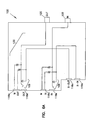
- FIG. 6A shows a schematic diagram of the electrical circuit 132 of switching jack module 100.
- a digital signal cross-connect (dsx) module typically the rear connectors 120 and 122 are connected to cables leading to remote equipment.
- the connectors 120 and 122 are electrically connected to cross-connect ports 118c.
- the cross-connect ports 118c are connected by jumper cables to cross-connect ports of another cross-connect module.
- the access ports 118d and 118e may be periodically used to interrupt the signal passing between the cross-connect ports 118c and the connectors 120 and 122 and to switch (via switches 109) the signals to pass through cables inserted into the access ports 118d and 118e.
- the monitor ports 118a and 118b may be used to monitor the signals passing through the module.
- the preferred embodiment shown in the figures incorporates BNC connectors 120 and 122. It is to be understood that the present invention may incorporate many other types of connectors, for example TNC, 1.6/5.6, Type 43, twisted pair connectors including DB style, or ribbon styles, or other cable connectors such as fiber optic connectors.
- the present invention may be employed to slidably mount many types of connectors such as ports 118.
- the ports may be slidably mounted to a panel or chassis system with or without additional connectors on an opposing surface or panel.
- Side surfaces 114 and 116 both define guide-slots 160 and 162.
- the guide-slots are characterized by a length which lies parallel to the direction the connectors 120 and 122 slide when transitioning between the first position and the second position.
- a carriage 130 is shown for supporting the connectors 120 and 122.
- the carriage 130 slides with the connectors 120 and 122 within the connector housing 105.
- the carriage 130 may include guide members such as guiderails 164 and 166.
- the guiderails 164 and 166 are received in guide-slots 160 and 162 of the connector housing 105 to retain the carriage 130 within the housing and guide the carriage 130 as it transitions between first and second positions.
- the carriage 130 and housing 105 could be reconfigured so that the carriage 130 defines the guide-slot which receives a guiderail or other guide member included in the connector housing.
- the carriage assembly 131 includes a carriage 130 and connectors 120 and 122.
- the carriage 130 includes first and second carriage members 170 and 172.
- Carriage members 170 and 172 define recesses 174 for receiving a connector therein.
- Connectors 120 and 122 are trapped between carriage members 170 and 172 in recesses 174.
- Connectors 120 and 122 may include collars 176 spaced apart along the connectors. The recessed portion of carriage members 170 and 172 may then be received between the connector collars 176 to prevent the connectors from being axially removed from the carriage 130.
- Carriage members 170 and 172 include posts 178 and eyes 179.
- Posts 178 have a ramped surface 180.
- Eyes 179 have a retaining edge 181.
- Posts 178 are received by eyes 179 so that the retaining edge 181 retains the carriage members 170 and 172 in a mating arrangement trapping the connectors 120 and 122 between them.
- Carriage 130 may be made of plastic.
- carriage member 170 is configured so that an identically shaped carriage member when rotated 180 degrees can be coupled to carriage member 170 in a mating arrangement.
- Carriage member 172 is actually identical to carriage member 170, only carriage member 172 is turned 180 degrees to be in a mating position relative to carriage member 170. By configuring the carriage members in this way, both carriage members 170 and 172 may be formed in the same mold, reducing the number of different parts used in the assembly.
- carriage 130 in the figures receives two connectors 120 and 122, but alternative embodiments could include single connector carriages receiving only one connector which would allow each individual connector to be positioned independently of other connectors.
- the carriage 130 could be configured to receive more than two connectors.
- the connector housing could also be configured with a larger connector window or multiple connector windows to allow the carriage and connectors to be positioned in more than two positions.
- a three position system could include an intermediate position, an upper position, and a lower position.
- the connector housing 105 defines first and second apertures 190 and 192 connected by a channel 194.
- Carriage 130 includes a protruding tab 196 received in the first aperture 190.
- the protruding tab extends from a flexible lever 191.
- the protruding tab 196 includes edges 197 and 199 which retain the carriage 130 and the connectors 120 and 122 in the first position by opposing edges of the apertures of the connector housing 105.
- the protruding tab 196 is depressible so that when depressed, the carriage 130 and connectors 120 and 122 may slide to the second position (shown in FIGS. 1 and 3). In the second position, protruding tab 196' is received in the second aperture 192 thereby retaining the carriage 130 and connectors in the second position.
- the assembly may not include a means for retaining the carriage and connectors in the selected position.
- the present invention could be used during installation to slide the connectors from an initial position into a more accessible position in order to connect or disconnect a cable to or from the connector. Then the connector could be allowed to slide back down into its original position.
- the carriage and connector housing could be configured with various opposing edges in order to retain the carriage and connectors in a selected position. These could include engaging tabs and slots, push-and-slide, or pull-and-slide mechanisms.
- FIGS. 10 - 19 show examples of alternatives for achieving this.
- FIG. 10 shows a connector assembly 200 including a carriage 230 with a single protruding tab 235 which can be transitioned between first and second apertures 238 and 240 in connector housing 215 by either depressing or pulling tab 235 from aperture 238 and sliding the carriage 230 with the connectors 210 and 220.
- FIG. 11 shows two modules according to the embodiment of FIG. 10 with the connectors arranged in a staggered pattern.
- FIG. 12 shows a connector assembly 300 including a carriage 330 with connectors 310 and 320.
- Connector housing 315 defines a fastener hole 340 which receives a fastener 350.
- Fastener 350 may be inserted into hole 340 to secure the carriage 330 in a selected position, fastener 350 may then be removed to allow carriage and connectors to transition to a different position as shown in FIG. 13.
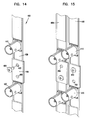
- FIG. 14 shows a connector assembly 400 including a carriage 430 with connectors 410 and 420.
- Connector housing 415 defines an fastener aperture 455 and 460 for both first and second positions.
- Carriage 430 may define a mating fastener receptacle which is aligned beneath aperture 455 when the carriage 430 is in the a first position and which is aligned beneath aperture 460 when the carriage 430 is in a second position.
- Fastener 450 may be inserted through connector housing 415 into the fastener receptacle to retain the carriage 430 in a selected position.
- FIG. 15 show two assemblies according to the embodiment of FIG. 14 in a staggered arrangement.
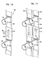
- FIG. 16 shows a connector assembly 500 including a carriage 530 with connectors 510 and 520.
- Connector housing 515 defines a slot 540.
- Slot 540 receives fastener 560 which may be tightened to retain carriage 530 and connectors in a selected position or which may be loosened to allow the carriage to slide and transition to a new position.
- FIG. 17 shows two assemblies according to the embodiment of FIG. 15 in a staggered arrangement.
- FIG. 18 shows a connector assembly 600 including a carriage 630 and connectors 610 and 620.
- the connectors themselves act as the depressible element to allow transitions between positions.
- the connectors when depressed would disengage interior features of the connector housing to allow transitions between positions.
- Connector 620 is shown depressed indicating that connector 620 may be transitioned to another position.
- FIG. 19 shows two assemblies according to the embodiment of FIG. 18 in a staggered arrangement.
- a staggered arrangement of connectors can be achieved.
- the method would include the step of sliding a slidable connector into a position on a first module and placing the first module adjacent a second module with a connector in a different position.
- the two modules could first be placed next to each other and then one sliding connector would be slid to a staggered position relative to the connector in the second module.
- the present invention can be employed in various applications.
- the invention is not limited to the preferred embodiment disclosed herein.
- the connector housing may be any panel having a flat surface in which connectors are disposed. Having described the present invention in its preferred embodiment, modifications may occur to one skilled in the art.
Landscapes
- Engineering & Computer Science (AREA)
- Computer Networks & Wireless Communication (AREA)
- Details Of Connecting Devices For Male And Female Coupling (AREA)
- Connector Housings Or Holding Contact Members (AREA)
- Coupling Device And Connection With Printed Circuit (AREA)
- Mechanical Coupling Of Light Guides (AREA)
- Manufacturing Of Electrical Connectors (AREA)
- Cable Accessories (AREA)
- Input Circuits Of Receivers And Coupling Of Receivers And Audio Equipment (AREA)
- Mounting, Exchange, And Manufacturing Of Dies (AREA)
Claims (9)
- Ensemble de connecteurs comprenant:un boîtier (105) ayant des premier et second panneaux opposés (110, 112), le premier panneau (112) ayant une pluralité de connecteurs (118) disposés à l'intérieur de celui-ci, le second panneau (110) ayant une pluralité de connecteurs (120, 122) disposés à l'intérieur de celui-ci, dans lequel les connecteurs (118) dans le premier panneau (112) sont raccordés électriquement aux connecteurs (120, 122) disposés dans le second panneau (110), les connecteurs (120, 122) dans le second panneau (110) pouvant coulisser entre des premières positions et des secondes positions par rapport au boîtier (105), les premières positions étant déplacées par rapport aux secondes positions,caractérisé par :les connecteurs coulissants (120, 122) produisant un agencement en quinconce ou pas en quinconce des connecteurs lorsque l'ensemble de connecteurs est positionné de manière adjacente à un autre ensemble de connecteurs.
- Ensemble de connecteurs selon la revendication 1, dans lequel les connecteurs (118) sont des ports, les ports comprenant un port d'accès (118d ou 118e), un port de moniteur (118a ou 118b), et un port de répartiteur (118c).
- Ensemble de connecteurs selon la revendication 2, dans lequel les ports sont électriquement couplés aux connecteurs par un circuit de commutation (132).
- Ensemble de connecteurs selon la revendication 2, comprenant en outre un chariot (130) qui reçoit une pluralité de connecteurs coulissants, le chariot pouvant coulisser avec les connecteurs.
- Ensemble de connecteurs selon la revendication 4, comprenant en outre des moyens de retenue (190, 192, 196) pour retenir le chariot et dans une position sélectionnée.
- Procédé pour agencer une pluralité de connecteurs dans un agencement en quinconce, le procédé étant caractérisé par les étapes consistant à :prévoir un premier ensemble de connecteurs (100) selon l'une quelconque des revendications précédentes, ayant un premier connecteur disposé à l'intérieur de celui-ci, le premier connecteur pouvant coulisser entre une première et une seconde position,prévoir un second ensemble de connecteurs (100) selon l'une quelconque des revendications précédentes, ayant un second connecteur disposé à l'intérieur de celui-ci, le second connecteur pouvant coulisser entre une première et une seconde position,placer le premier ensemble de connecteurs de manière adjacente au second ensemble de connecteurs ;faire coulisser l'un des connecteurs dans une position différente de la position de l'autre connecteur pour produire un agencement en quinconce des connecteurs.
- Procédé selon la revendication 6, comprenant en outre l'étape consistant à faire coulisser le second connecteur dans une position sélectionnée.
- Procédé selon la revendication 6, dans lequel l'étape consistant à faire coulisser l'un des connecteurs est réalisée après l'étape consistant à placer le premier ensemble de connecteurs adjacent au second ensemble de connecteurs.
- Procédé selon la revendication 6, comprenant en outre l'étape consistant à bloquer le connecteur coulissant en position.
Priority Applications (1)
| Application Number | Priority Date | Filing Date | Title |
|---|---|---|---|
| EP07000813A EP1793454B1 (fr) | 2001-04-13 | 2002-04-11 | Dispositif de connexion avec connecteurs coulissants à l'arrière |
Applications Claiming Priority (3)
| Application Number | Priority Date | Filing Date | Title |
|---|---|---|---|
| US835067 | 1986-02-28 | ||
| US09/835,067 US6533616B2 (en) | 2001-04-13 | 2001-04-13 | DSX jack including sliding rear connector |
| PCT/US2002/011579 WO2002084802A2 (fr) | 2001-04-13 | 2002-04-11 | Douille dsx comprenant un connecteur arriere coulissant |
Related Child Applications (1)
| Application Number | Title | Priority Date | Filing Date |
|---|---|---|---|
| EP07000813A Division EP1793454B1 (fr) | 2001-04-13 | 2002-04-11 | Dispositif de connexion avec connecteurs coulissants à l'arrière |
Publications (2)
| Publication Number | Publication Date |
|---|---|
| EP1391010A2 EP1391010A2 (fr) | 2004-02-25 |
| EP1391010B1 true EP1391010B1 (fr) | 2007-01-24 |
Family
ID=25268480
Family Applications (2)
| Application Number | Title | Priority Date | Filing Date |
|---|---|---|---|
| EP07000813A Expired - Lifetime EP1793454B1 (fr) | 2001-04-13 | 2002-04-11 | Dispositif de connexion avec connecteurs coulissants à l'arrière |
| EP02762071A Expired - Lifetime EP1391010B1 (fr) | 2001-04-13 | 2002-04-11 | Assemblage de connecteurs coulissants |
Family Applications Before (1)
| Application Number | Title | Priority Date | Filing Date |
|---|---|---|---|
| EP07000813A Expired - Lifetime EP1793454B1 (fr) | 2001-04-13 | 2002-04-11 | Dispositif de connexion avec connecteurs coulissants à l'arrière |
Country Status (10)
| Country | Link |
|---|---|
| US (4) | US6533616B2 (fr) |
| EP (2) | EP1793454B1 (fr) |
| AT (2) | ATE352887T1 (fr) |
| AU (1) | AU2002307277A1 (fr) |
| BR (2) | BRPI0208848B1 (fr) |
| CA (1) | CA2443703C (fr) |
| DE (2) | DE60238797D1 (fr) |
| ES (2) | ES2355602T3 (fr) |
| MX (1) | MXPA03009319A (fr) |
| WO (1) | WO2002084802A2 (fr) |
Families Citing this family (67)
| Publication number | Priority date | Publication date | Assignee | Title |
|---|---|---|---|---|
| US6575593B2 (en) * | 2000-05-20 | 2003-06-10 | Mark Howard Krietzman | IEEE 1394 or USB powered computer light |
| US6802629B2 (en) * | 2001-05-21 | 2004-10-12 | Acco Brands, Inc. | IEEE 1394 or USB powered computer lights |
| US20040017677A1 (en) * | 2000-05-20 | 2004-01-29 | Krietzman Mark Howard | IEEE 1394 or USB powered computer light |
| US6533616B2 (en) * | 2001-04-13 | 2003-03-18 | Adc Telecommunications, Inc. | DSX jack including sliding rear connector |
| US6788868B2 (en) * | 2001-12-22 | 2004-09-07 | Scientific-Atlanta, Inc. | Fiber optic module connector cleaning slide |
| US6830486B2 (en) * | 2002-07-19 | 2004-12-14 | Adc Telecommunications, Inc. | Digital switching cross-connect module |
| US7070457B2 (en) * | 2002-07-19 | 2006-07-04 | Adc Telecommunications, Inc. | Telecommunications connector |
| FR2849965B1 (fr) * | 2003-01-15 | 2016-04-01 | Infra Sa | Organe d'agencement de moyens de connexion, dispositif de montage de moyens de connexion et baie porteuse. |
| US6885798B2 (en) | 2003-09-08 | 2005-04-26 | Adc Telecommunications, Inc. | Fiber optic cable and furcation module |
| US6848948B1 (en) * | 2003-11-03 | 2005-02-01 | Adc Telecommunications, Inc. | Jack with modular mounting sleeve |
| US6932624B1 (en) * | 2004-02-05 | 2005-08-23 | Panamax | Modular signal and power connection device |
| US7029323B1 (en) * | 2004-09-27 | 2006-04-18 | Adc Telecommunications, Inc. | High density mount for a co-axial connector |
| US7376322B2 (en) * | 2004-11-03 | 2008-05-20 | Adc Telecommunications, Inc. | Fiber optic module and system including rear connectors |
| US7074080B1 (en) * | 2005-04-21 | 2006-07-11 | Adc Telecommunications, Inc. | Modular mounting sleeve for jack |
| WO2006115813A1 (fr) * | 2005-04-21 | 2006-11-02 | Adc Telecommunications, Inc. | Manchon à montage modulaire pour vérin |
| US7400813B2 (en) * | 2005-05-25 | 2008-07-15 | Adc Telecommunications, Inc. | Fiber optic splitter module |
| US7376323B2 (en) * | 2005-05-25 | 2008-05-20 | Adc Telecommunications, Inc. | Fiber optic adapter module |
| US7238035B2 (en) * | 2005-06-14 | 2007-07-03 | Trompeter Electronics, Inc. | Normal-through jack with monitor and test ports |
| US7636507B2 (en) * | 2005-06-17 | 2009-12-22 | Adc Telecommunications, Inc. | Compact blind mateable optical splitter |
| US7346254B2 (en) * | 2005-08-29 | 2008-03-18 | Adc Telecommunications, Inc. | Fiber optic splitter module with connector access |
| US7418181B2 (en) * | 2006-02-13 | 2008-08-26 | Adc Telecommunications, Inc. | Fiber optic splitter module |
| US7591677B2 (en) * | 2006-04-21 | 2009-09-22 | Adc Telecommunications, Inc. | High density coaxial jack and panel |
| US7393249B2 (en) * | 2006-04-21 | 2008-07-01 | Trompeter Electronics, Inc. | Interconnection and monitoring module |
| US7391954B1 (en) | 2007-05-30 | 2008-06-24 | Corning Cable Systems Llc | Attenuated optical splitter module |
| US20080298748A1 (en) * | 2007-05-31 | 2008-12-04 | Terry Dean Cox | Direct-connect optical splitter module |
| US20080298743A1 (en) * | 2007-05-31 | 2008-12-04 | Konstantinos Saravanos | Microsplitter module for optical connectivity |
| WO2009018668A1 (fr) * | 2007-08-09 | 2009-02-12 | Belden Cdt Canada Inc. | Ensemble de connecteurs télescopiques |
| US8798427B2 (en) | 2007-09-05 | 2014-08-05 | Corning Cable Systems Llc | Fiber optic terminal assembly |
| US7885505B2 (en) | 2007-10-22 | 2011-02-08 | Adc Telecommunications, Inc. | Wavelength division multiplexing module |
| US7536075B2 (en) * | 2007-10-22 | 2009-05-19 | Adc Telecommunications, Inc. | Wavelength division multiplexing module |
| US8107816B2 (en) | 2008-01-29 | 2012-01-31 | Adc Telecommunications, Inc. | Wavelength division multiplexing module |
| CH702048B1 (de) * | 2008-03-14 | 2011-04-29 | Huber+Suhner Ag | Mehrfach-Koaxialkabel-Steckverbindung sowie Verfahren zum Montieren einer solchen Mehrfach-Koaxialkabel-Steckverbindung. |
| US11294136B2 (en) | 2008-08-29 | 2022-04-05 | Corning Optical Communications LLC | High density and bandwidth fiber optic apparatuses and related equipment and methods |
| US8452148B2 (en) * | 2008-08-29 | 2013-05-28 | Corning Cable Systems Llc | Independently translatable modules and fiber optic equipment trays in fiber optic equipment |
| EP2344915A4 (fr) | 2008-10-09 | 2015-01-21 | Corning Cable Sys Llc | Terminal à fibre optique ayant un panneau adaptateur portant à la fois les fibres d'entrée et de sortie provenant d'un diviseur optique |
| US8879882B2 (en) | 2008-10-27 | 2014-11-04 | Corning Cable Systems Llc | Variably configurable and modular local convergence point |
| WO2010083369A1 (fr) * | 2009-01-15 | 2010-07-22 | Adc Telecommunications, Inc. | Module à fibre optique, châssis et adaptateur |
| EP2237091A1 (fr) | 2009-03-31 | 2010-10-06 | Corning Cable Systems LLC | Terminal à fibres optiques pouvant être assemblé de manière amovible |
| DE20160489T1 (de) | 2009-06-19 | 2024-06-20 | Corning Optical Communications LLC | Glasfaservorrichtungen mit hoher dichte und bandbreite und zugehörige ausrüstung und verfahren |
| US8467651B2 (en) * | 2009-09-30 | 2013-06-18 | Ccs Technology Inc. | Fiber optic terminals configured to dispose a fiber optic connection panel(s) within an optical fiber perimeter and related methods |
| US9547144B2 (en) | 2010-03-16 | 2017-01-17 | Corning Optical Communications LLC | Fiber optic distribution network for multiple dwelling units |
| US8792767B2 (en) | 2010-04-16 | 2014-07-29 | Ccs Technology, Inc. | Distribution device |
| WO2011134143A1 (fr) | 2010-04-27 | 2011-11-03 | Adc Communications (Shanghai) Co., Ltd. | Module à fibres optiques et châssis |
| US9720197B2 (en) | 2010-10-19 | 2017-08-01 | Corning Optical Communications LLC | Transition box for multiple dwelling unit fiber optic distribution network |
| US8935849B2 (en) * | 2011-03-10 | 2015-01-20 | Fci Americas Technology Llc | Method for mounting a cable connector onto a panel |
| US9182563B2 (en) | 2011-03-31 | 2015-11-10 | Adc Telecommunications, Inc. | Adapter plate for fiber optic module |
| WO2013033890A1 (fr) | 2011-09-06 | 2013-03-14 | Adc Telecommunications, Inc. | Adaptateur pour module de fibre optique |
| US9219546B2 (en) | 2011-12-12 | 2015-12-22 | Corning Optical Communications LLC | Extremely high frequency (EHF) distributed antenna systems, and related components and methods |
| US10110307B2 (en) | 2012-03-02 | 2018-10-23 | Corning Optical Communications LLC | Optical network units (ONUs) for high bandwidth connectivity, and related components and methods |
| US9004778B2 (en) | 2012-06-29 | 2015-04-14 | Corning Cable Systems Llc | Indexable optical fiber connectors and optical fiber connector arrays |
| US9049500B2 (en) | 2012-08-31 | 2015-06-02 | Corning Cable Systems Llc | Fiber optic terminals, systems, and methods for network service management |
| US8909019B2 (en) | 2012-10-11 | 2014-12-09 | Ccs Technology, Inc. | System comprising a plurality of distribution devices and distribution device |
| EP2936228A1 (fr) | 2012-12-19 | 2015-10-28 | Tyco Electronics Raychem BVBA | Dispositif de distribution avec coupleurs ajoutés par incréments |
| US9301030B2 (en) | 2013-11-11 | 2016-03-29 | Commscope Technologies Llc | Telecommunications module |
| WO2015193384A2 (fr) | 2014-06-17 | 2015-12-23 | Tyco Electronics Raychem Bvba | Système de distribution de câble |
| US9395509B2 (en) | 2014-06-23 | 2016-07-19 | Commscope Technologies Llc | Fiber cable fan-out assembly and method |
| US10054753B2 (en) | 2014-10-27 | 2018-08-21 | Commscope Technologies Llc | Fiber optic cable with flexible conduit |
| GB2538815B (en) * | 2015-05-26 | 2017-09-20 | Secure Int Holdings Pte Ltd | Utility meter |
| AU2015207954C1 (en) | 2015-07-31 | 2022-05-05 | Adc Communications (Australia) Pty Limited | Cable breakout assembly |
| WO2017034931A1 (fr) | 2015-08-21 | 2017-03-02 | Commscope Technologies Llc | Module de télécommunications |
| US10606009B2 (en) | 2015-12-01 | 2020-03-31 | CommScope Connectivity Belgium BVBA | Cable distribution system with fan out devices |
| EP3408701B1 (fr) | 2016-01-28 | 2023-04-26 | CommScope Connectivity Belgium BVBA | Enceinte modulaire de telecommunications |
| WO2017161310A1 (fr) | 2016-03-18 | 2017-09-21 | Commscope Technologies Llc | Agencements de conduit de sortance d'un câble à fibre optique ; composants et procédés |
| US10222571B2 (en) | 2016-04-07 | 2019-03-05 | Commscope Technologies Llc | Telecommunications module and frame |
| US10890730B2 (en) | 2016-08-31 | 2021-01-12 | Commscope Technologies Llc | Fiber optic cable clamp and clamp assembly |
| WO2018071481A1 (fr) | 2016-10-13 | 2018-04-19 | Commscope Technologies Llc | Ensemble de transition de dérivation de fibre optique incorporant une fiche époxy et un soulagement de contrainte de câble |
| EP3622336A4 (fr) | 2017-05-08 | 2021-01-20 | Commscope Technologies LLC | Ensemble de transition de dérivation de fibres optiques |
Family Cites Families (22)
| Publication number | Priority date | Publication date | Assignee | Title |
|---|---|---|---|---|
| FR931803A (fr) * | 1946-08-06 | 1948-03-04 | Radioelectriques Lab | Dispositif de connexion pour circuits électriques contenus dans des tiroirs d'un meuble |
| NL135644C (fr) * | 1964-02-27 | |||
| FR2148699A5 (fr) * | 1971-07-30 | 1973-03-23 | Socapex | |
| US4588251A (en) * | 1985-04-22 | 1986-05-13 | Trimm, Inc. | Telephone jack assembly |
| US4712232A (en) * | 1986-03-14 | 1987-12-08 | Armor Metals, Inc. | Multiple telephone jack slide assembly |
| US5214673A (en) * | 1989-08-04 | 1993-05-25 | Adc Telecommunications, Inc. | Digital cross connect assembly |
| US5129842A (en) * | 1991-04-08 | 1992-07-14 | Digital Equipment Corporation | Modular patch panel |
| US5233501A (en) * | 1992-02-27 | 1993-08-03 | Telect, Inc. | Digital telecommunication network cross-connect module having a printed circuit board connected to jack switches |
| WO1994008429A1 (fr) * | 1992-10-05 | 1994-04-14 | Adc Telecommunications, Inc. | Ensemble modules de jack |
| TW232757B (en) | 1994-01-21 | 1994-10-21 | Adc Telecommunications Inc | High-density fiber distribution frame |
| US5582525A (en) * | 1995-01-12 | 1996-12-10 | Adc Telecommunications, Inc. | Drop and insert card |
| US5647763A (en) * | 1995-02-09 | 1997-07-15 | Superior Modular Products Incorporated | Multi-media cross connect system |
| US5746617A (en) * | 1996-07-03 | 1998-05-05 | Quality Microwave Interconnects, Inc. | Self aligning coaxial connector assembly |
| US5913701A (en) * | 1997-02-28 | 1999-06-22 | Adc Telecommunications, Inc. | DSX module with removable switching jack |
| US5885112A (en) | 1997-11-17 | 1999-03-23 | Adc Telecommunications, Inc. | Coax connector bay and drawer |
| US5938478A (en) * | 1998-02-05 | 1999-08-17 | Telect, Inc. | Jack assembly & panel system |
| US6116961A (en) * | 1998-11-12 | 2000-09-12 | Adc Telecommunications, Inc. | Jack assembly |
| US6547588B1 (en) * | 1999-10-28 | 2003-04-15 | Tekcon Electronics Corp. | Embedded type connector |
| US6497586B1 (en) * | 1999-11-19 | 2002-12-24 | Steven W. Wilson | Structural truss system with adjustable mechanical mounting track and internal conduit accessible from removable sidewall |
| US6283796B1 (en) * | 2000-03-23 | 2001-09-04 | Hon Hai Precision Ind. Co., Ltd. | RJ-receptacle connector with anti-incorrect-insertion device |
| US6533616B2 (en) | 2001-04-13 | 2003-03-18 | Adc Telecommunications, Inc. | DSX jack including sliding rear connector |
| US6729910B2 (en) * | 2001-06-01 | 2004-05-04 | Telect, Inc. | DSX jack LED activation and grounding system |
-
2001
- 2001-04-13 US US09/835,067 patent/US6533616B2/en not_active Expired - Lifetime
- 2001-12-17 US US10/023,334 patent/US6457999B1/en not_active Expired - Lifetime
-
2002
- 2002-04-11 AU AU2002307277A patent/AU2002307277A1/en not_active Abandoned
- 2002-04-11 EP EP07000813A patent/EP1793454B1/fr not_active Expired - Lifetime
- 2002-04-11 AT AT02762071T patent/ATE352887T1/de active
- 2002-04-11 BR BRPI0208848-7A patent/BRPI0208848B1/pt unknown
- 2002-04-11 ES ES07000813T patent/ES2355602T3/es not_active Expired - Lifetime
- 2002-04-11 DE DE60238797T patent/DE60238797D1/de not_active Expired - Lifetime
- 2002-04-11 WO PCT/US2002/011579 patent/WO2002084802A2/fr not_active Ceased
- 2002-04-11 MX MXPA03009319A patent/MXPA03009319A/es active IP Right Grant
- 2002-04-11 AT AT07000813T patent/ATE493777T1/de not_active IP Right Cessation
- 2002-04-11 DE DE60217856T patent/DE60217856T2/de not_active Expired - Lifetime
- 2002-04-11 EP EP02762071A patent/EP1391010B1/fr not_active Expired - Lifetime
- 2002-04-11 CA CA2443703A patent/CA2443703C/fr not_active Expired - Fee Related
- 2002-04-11 ES ES02762071T patent/ES2281537T3/es not_active Expired - Lifetime
- 2002-04-11 BR BR0208848-7A patent/BR0208848A/pt not_active IP Right Cessation
-
2003
- 2003-02-25 US US10/374,637 patent/US6761594B2/en not_active Expired - Lifetime
-
2004
- 2004-07-09 US US10/888,700 patent/US6872097B2/en not_active Expired - Lifetime
Also Published As
| Publication number | Publication date |
|---|---|
| ES2281537T3 (es) | 2007-10-01 |
| HK1063535A1 (en) | 2004-12-31 |
| CA2443703C (fr) | 2010-06-22 |
| ATE493777T1 (de) | 2011-01-15 |
| EP1793454A3 (fr) | 2007-06-13 |
| EP1793454B1 (fr) | 2010-12-29 |
| US20020151222A1 (en) | 2002-10-17 |
| HK1103176A1 (en) | 2007-12-14 |
| BR0208848A (pt) | 2004-03-09 |
| ATE352887T1 (de) | 2007-02-15 |
| DE60217856D1 (de) | 2007-03-15 |
| CA2443703A1 (fr) | 2002-10-24 |
| DE60217856T2 (de) | 2007-06-21 |
| US6872097B2 (en) | 2005-03-29 |
| EP1391010A2 (fr) | 2004-02-25 |
| ES2355602T3 (es) | 2011-03-29 |
| MXPA03009319A (es) | 2004-11-12 |
| WO2002084802A2 (fr) | 2002-10-24 |
| US6761594B2 (en) | 2004-07-13 |
| US6457999B1 (en) | 2002-10-01 |
| US20040259425A1 (en) | 2004-12-23 |
| US20030134541A1 (en) | 2003-07-17 |
| US6533616B2 (en) | 2003-03-18 |
| DE60238797D1 (de) | 2011-02-10 |
| WO2002084802A3 (fr) | 2003-12-04 |
| US20020151221A1 (en) | 2002-10-17 |
| EP1793454A2 (fr) | 2007-06-06 |
| BRPI0208848B1 (pt) | 2017-10-17 |
| AU2002307277A1 (en) | 2002-10-28 |
Similar Documents
| Publication | Publication Date | Title |
|---|---|---|
| EP1391010B1 (fr) | Assemblage de connecteurs coulissants | |
| US4239316A (en) | Electrical connectors and assemblies therefor | |
| US4303296A (en) | Modular interface connector | |
| EP1608185B1 (fr) | Jack d'interconnexion | |
| US5413494A (en) | Jack module assembly | |
| US4840568A (en) | Jack assembly | |
| US6875060B2 (en) | High density patching system | |
| US7121896B2 (en) | Digital switching cross-connect module | |
| KR20060123251A (ko) | 모듈식 탑재 슬리브를 지닌 잭 | |
| WO1996038884A1 (fr) | Module a jacks de telecommunications avec fond de panier interchangeable | |
| US5438617A (en) | Low frequency digital network cross-connect panel | |
| EP0608792B1 (fr) | Module de terminaison repositionnable | |
| WO2013091009A1 (fr) | Système de câblage de télécommunications, et module de connexion électrique et interface de blindage associée | |
| AU2392199A (en) | High density high performance telecommunications/data link and connector with tap and contact displacement assembly | |
| CA2572768C (fr) | Systeme de raccordement haute densite a structure allongee | |
| HK1063535B (en) | Assembly with slidable connectors | |
| HK1103176B (en) | Connector arrangement including sliding rear connectors | |
| US20040014366A1 (en) | Pin jack for a digital switching cross-connect module | |
| US4797124A (en) | Connector bodies and assemblies | |
| AU648439B2 (en) | Digital cross-connect assembly | |
| CA1284832C (fr) | Connecteur de telecommunication | |
| CA1284831C (fr) | Connecteurs |
Legal Events
| Date | Code | Title | Description |
|---|---|---|---|
| PUAI | Public reference made under article 153(3) epc to a published international application that has entered the european phase |
Free format text: ORIGINAL CODE: 0009012 |
|
| 17P | Request for examination filed |
Effective date: 20031112 |
|
| AK | Designated contracting states |
Kind code of ref document: A2 Designated state(s): AT BE CH CY DE DK ES FI FR GB GR IE IT LI LU MC NL PT SE TR |
|
| AX | Request for extension of the european patent |
Extension state: AL LT LV MK RO SI |
|
| REG | Reference to a national code |
Ref country code: HK Ref legal event code: DE Ref document number: 1063535 Country of ref document: HK |
|
| RTI1 | Title (correction) |
Free format text: ASSEMBLY WITH SLIDABLE CONNECTORS |
|
| GRAP | Despatch of communication of intention to grant a patent |
Free format text: ORIGINAL CODE: EPIDOSNIGR1 |
|
| GRAS | Grant fee paid |
Free format text: ORIGINAL CODE: EPIDOSNIGR3 |
|
| GRAA | (expected) grant |
Free format text: ORIGINAL CODE: 0009210 |
|
| AK | Designated contracting states |
Kind code of ref document: B1 Designated state(s): AT BE CH CY DE DK ES FI FR GB GR IE IT LI LU MC NL PT SE TR |
|
| PG25 | Lapsed in a contracting state [announced via postgrant information from national office to epo] |
Ref country code: FI Free format text: LAPSE BECAUSE OF FAILURE TO SUBMIT A TRANSLATION OF THE DESCRIPTION OR TO PAY THE FEE WITHIN THE PRESCRIBED TIME-LIMIT Effective date: 20070124 Ref country code: NL Free format text: LAPSE BECAUSE OF FAILURE TO SUBMIT A TRANSLATION OF THE DESCRIPTION OR TO PAY THE FEE WITHIN THE PRESCRIBED TIME-LIMIT Effective date: 20070124 Ref country code: DK Free format text: LAPSE BECAUSE OF FAILURE TO SUBMIT A TRANSLATION OF THE DESCRIPTION OR TO PAY THE FEE WITHIN THE PRESCRIBED TIME-LIMIT Effective date: 20070124 |
|
| REG | Reference to a national code |
Ref country code: GB Ref legal event code: FG4D |
|
| REG | Reference to a national code |
Ref country code: CH Ref legal event code: EP |
|
| REG | Reference to a national code |
Ref country code: IE Ref legal event code: FG4D |
|
| REF | Corresponds to: |
Ref document number: 60217856 Country of ref document: DE Date of ref document: 20070315 Kind code of ref document: P |
|
| PG25 | Lapsed in a contracting state [announced via postgrant information from national office to epo] |
Ref country code: SE Free format text: LAPSE BECAUSE OF FAILURE TO SUBMIT A TRANSLATION OF THE DESCRIPTION OR TO PAY THE FEE WITHIN THE PRESCRIBED TIME-LIMIT Effective date: 20070424 |
|
| REG | Reference to a national code |
Ref country code: CH Ref legal event code: NV Representative=s name: MICHELI & CIE SA |
|
| REG | Reference to a national code |
Ref country code: HK Ref legal event code: GR Ref document number: 1063535 Country of ref document: HK |
|
| REG | Reference to a national code |
Ref country code: GR Ref legal event code: EP Ref document number: 20070401106 Country of ref document: GR |
|
| PG25 | Lapsed in a contracting state [announced via postgrant information from national office to epo] |
Ref country code: PT Free format text: LAPSE BECAUSE OF FAILURE TO SUBMIT A TRANSLATION OF THE DESCRIPTION OR TO PAY THE FEE WITHIN THE PRESCRIBED TIME-LIMIT Effective date: 20070625 |
|
| ET | Fr: translation filed | ||
| NLV1 | Nl: lapsed or annulled due to failure to fulfill the requirements of art. 29p and 29m of the patents act | ||
| REG | Reference to a national code |
Ref country code: ES Ref legal event code: FG2A Ref document number: 2281537 Country of ref document: ES Kind code of ref document: T3 |
|
| PLBE | No opposition filed within time limit |
Free format text: ORIGINAL CODE: 0009261 |
|
| STAA | Information on the status of an ep patent application or granted ep patent |
Free format text: STATUS: NO OPPOSITION FILED WITHIN TIME LIMIT |
|
| 26N | No opposition filed |
Effective date: 20071025 |
|
| PG25 | Lapsed in a contracting state [announced via postgrant information from national office to epo] |
Ref country code: MC Free format text: LAPSE BECAUSE OF NON-PAYMENT OF DUE FEES Effective date: 20070430 |
|
| PG25 | Lapsed in a contracting state [announced via postgrant information from national office to epo] |
Ref country code: CY Free format text: LAPSE BECAUSE OF FAILURE TO SUBMIT A TRANSLATION OF THE DESCRIPTION OR TO PAY THE FEE WITHIN THE PRESCRIBED TIME-LIMIT Effective date: 20070124 |
|
| PG25 | Lapsed in a contracting state [announced via postgrant information from national office to epo] |
Ref country code: LU Free format text: LAPSE BECAUSE OF NON-PAYMENT OF DUE FEES Effective date: 20070411 |
|
| PGFP | Annual fee paid to national office [announced via postgrant information from national office to epo] |
Ref country code: TR Payment date: 20100324 Year of fee payment: 9 |
|
| PGFP | Annual fee paid to national office [announced via postgrant information from national office to epo] |
Ref country code: FR Payment date: 20110504 Year of fee payment: 10 Ref country code: IE Payment date: 20110426 Year of fee payment: 10 Ref country code: GR Payment date: 20110429 Year of fee payment: 10 Ref country code: CH Payment date: 20110425 Year of fee payment: 10 |
|
| PGFP | Annual fee paid to national office [announced via postgrant information from national office to epo] |
Ref country code: GB Payment date: 20110426 Year of fee payment: 10 Ref country code: BE Payment date: 20110426 Year of fee payment: 10 Ref country code: AT Payment date: 20110321 Year of fee payment: 10 |
|
| PGFP | Annual fee paid to national office [announced via postgrant information from national office to epo] |
Ref country code: DE Payment date: 20120427 Year of fee payment: 11 |
|
| PGFP | Annual fee paid to national office [announced via postgrant information from national office to epo] |
Ref country code: IT Payment date: 20120423 Year of fee payment: 11 |
|
| BERE | Be: lapsed |
Owner name: ADC TELECOMMUNICATIONS, INC. Effective date: 20120430 |
|
| REG | Reference to a national code |
Ref country code: CH Ref legal event code: PL |
|
| REG | Reference to a national code |
Ref country code: AT Ref legal event code: MM01 Ref document number: 352887 Country of ref document: AT Kind code of ref document: T Effective date: 20120411 |
|
| GBPC | Gb: european patent ceased through non-payment of renewal fee |
Effective date: 20120411 |
|
| PGFP | Annual fee paid to national office [announced via postgrant information from national office to epo] |
Ref country code: ES Payment date: 20120426 Year of fee payment: 11 |
|
| REG | Reference to a national code |
Ref country code: IE Ref legal event code: MM4A |
|
| REG | Reference to a national code |
Ref country code: FR Ref legal event code: ST Effective date: 20121228 |
|
| REG | Reference to a national code |
Ref country code: GR Ref legal event code: ML Ref document number: 20070401106 Country of ref document: GR Effective date: 20121102 |
|
| PG25 | Lapsed in a contracting state [announced via postgrant information from national office to epo] |
Ref country code: BE Free format text: LAPSE BECAUSE OF NON-PAYMENT OF DUE FEES Effective date: 20120430 Ref country code: AT Free format text: LAPSE BECAUSE OF NON-PAYMENT OF DUE FEES Effective date: 20120411 Ref country code: CH Free format text: LAPSE BECAUSE OF NON-PAYMENT OF DUE FEES Effective date: 20120430 Ref country code: IE Free format text: LAPSE BECAUSE OF NON-PAYMENT OF DUE FEES Effective date: 20120411 Ref country code: LI Free format text: LAPSE BECAUSE OF NON-PAYMENT OF DUE FEES Effective date: 20120430 Ref country code: GB Free format text: LAPSE BECAUSE OF NON-PAYMENT OF DUE FEES Effective date: 20120411 |
|
| PG25 | Lapsed in a contracting state [announced via postgrant information from national office to epo] |
Ref country code: GR Free format text: LAPSE BECAUSE OF NON-PAYMENT OF DUE FEES Effective date: 20121102 Ref country code: FR Free format text: LAPSE BECAUSE OF NON-PAYMENT OF DUE FEES Effective date: 20120430 |
|
| PG25 | Lapsed in a contracting state [announced via postgrant information from national office to epo] |
Ref country code: TR Free format text: LAPSE BECAUSE OF NON-PAYMENT OF DUE FEES Effective date: 20120410 |
|
| PG25 | Lapsed in a contracting state [announced via postgrant information from national office to epo] |
Ref country code: DE Free format text: LAPSE BECAUSE OF NON-PAYMENT OF DUE FEES Effective date: 20131101 |
|
| REG | Reference to a national code |
Ref country code: DE Ref legal event code: R119 Ref document number: 60217856 Country of ref document: DE Effective date: 20131101 |
|
| PG25 | Lapsed in a contracting state [announced via postgrant information from national office to epo] |
Ref country code: IT Free format text: LAPSE BECAUSE OF NON-PAYMENT OF DUE FEES Effective date: 20130411 Ref country code: TR Free format text: LAPSE BECAUSE OF NON-PAYMENT OF DUE FEES Effective date: 20120411 |
|
| REG | Reference to a national code |
Ref country code: ES Ref legal event code: FD2A Effective date: 20140610 |
|
| PG25 | Lapsed in a contracting state [announced via postgrant information from national office to epo] |
Ref country code: ES Free format text: LAPSE BECAUSE OF NON-PAYMENT OF DUE FEES Effective date: 20130412 |