EP1391646A2 - Ventil - Google Patents
Ventil Download PDFInfo
- Publication number
- EP1391646A2 EP1391646A2 EP03018833A EP03018833A EP1391646A2 EP 1391646 A2 EP1391646 A2 EP 1391646A2 EP 03018833 A EP03018833 A EP 03018833A EP 03018833 A EP03018833 A EP 03018833A EP 1391646 A2 EP1391646 A2 EP 1391646A2
- Authority
- EP
- European Patent Office
- Prior art keywords
- valve
- sensor
- valve according
- housing
- calculation means
- Prior art date
- Legal status (The legal status is an assumption and is not a legal conclusion. Google has not performed a legal analysis and makes no representation as to the accuracy of the status listed.)
- Withdrawn
Links
Images


Classifications
-
- F—MECHANICAL ENGINEERING; LIGHTING; HEATING; WEAPONS; BLASTING
- F16—ENGINEERING ELEMENTS AND UNITS; GENERAL MEASURES FOR PRODUCING AND MAINTAINING EFFECTIVE FUNCTIONING OF MACHINES OR INSTALLATIONS; THERMAL INSULATION IN GENERAL
- F16K—VALVES; TAPS; COCKS; ACTUATING-FLOATS; DEVICES FOR VENTING OR AERATING
- F16K27/00—Construction of housing; Use of materials therefor
- F16K27/02—Construction of housing; Use of materials therefor of lift valves
- F16K27/0254—Construction of housing; Use of materials therefor of lift valves with conical shaped valve members
-
- F—MECHANICAL ENGINEERING; LIGHTING; HEATING; WEAPONS; BLASTING
- F16—ENGINEERING ELEMENTS AND UNITS; GENERAL MEASURES FOR PRODUCING AND MAINTAINING EFFECTIVE FUNCTIONING OF MACHINES OR INSTALLATIONS; THERMAL INSULATION IN GENERAL
- F16K—VALVES; TAPS; COCKS; ACTUATING-FLOATS; DEVICES FOR VENTING OR AERATING
- F16K1/00—Lift valves or globe valves, i.e. cut-off apparatus with closure members having at least a component of their opening and closing motion perpendicular to the closing faces
- F16K1/02—Lift valves or globe valves, i.e. cut-off apparatus with closure members having at least a component of their opening and closing motion perpendicular to the closing faces with screw-spindle
- F16K1/06—Special arrangements for improving the flow, e.g. special shape of passages or casings
- F16K1/10—Special arrangements for improving the flow, e.g. special shape of passages or casings in which the spindle is inclined to the general direction of flow
-
- G—PHYSICS
- G01—MEASURING; TESTING
- G01F—MEASURING VOLUME, VOLUME FLOW, MASS FLOW OR LIQUID LEVEL; METERING BY VOLUME
- G01F1/00—Measuring the volume flow or mass flow of fluid or fluent solid material wherein the fluid passes through a meter in a continuous flow
- G01F1/68—Measuring the volume flow or mass flow of fluid or fluent solid material wherein the fluid passes through a meter in a continuous flow by using thermal effects
- G01F1/684—Structural arrangements; Mounting of elements, e.g. in relation to fluid flow
- G01F1/6842—Structural arrangements; Mounting of elements, e.g. in relation to fluid flow with means for influencing the fluid flow
-
- G—PHYSICS
- G01—MEASURING; TESTING
- G01F—MEASURING VOLUME, VOLUME FLOW, MASS FLOW OR LIQUID LEVEL; METERING BY VOLUME
- G01F15/00—Details of, or accessories for, apparatus of groups G01F1/00 - G01F13/00 insofar as such details or appliances are not adapted to particular types of such apparatus
- G01F15/005—Valves
Definitions
- the present invention relates to a valve for liquids Installation in lines, especially a line valve for Water supply facilities.
- the valve has a housing and a valve bonnet.
- the housing has a first nozzle for connection to the line, a second connector for connection to the Line, as well as a third nozzle for receiving the Valve top.
- the valve upper part comprises a valve cone, which with a valve seat in the housing for adjusting the flow cooperates through the valve.
- the valve seat is included fluidically between the first and the second nozzle arranged.
- Such a valve is known from EP 0 946 910 B1 known.
- This publication concerns one Line regulating valve for regulating volume flows in Pipelines, with at least one in a flow housing integrated sensor records the volume flow and with a Evaluation unit and the flow characteristic of each associated housing containing data storage is connected.
- the sensor works according to a calorimetric measuring principle and is permanently and permanently installed in the line regulating valve. disadvantage the permanent installation of the sensors in the line regulating valve, that the sensors, especially for fittings with a smaller one Nominal size are disproportionately expensive compared to the overall valve. On Another disadvantage is that the sensor is not dirty can be cleaned.
- EP 0 592 398 B1 and DE 196 1925 C2 are valves for hot water systems partially known string control systems, which nozzle for the have removable insertion of sensors. These socks are attached in front of and behind a constriction of the valve, so that the sensors with their important elements for the measurement in front of and behind the constriction the flow through the valve are protruding into it.
- the bottleneck can be one act special aperture, such as in DE 196 1925 C2 disclosed, or the narrow point is concerned around the valve seat of the valve as it did from the other two Publications is known.
- the in the three mentioned publications disclosed valves are for measuring the Flow velocity or the flow rate after the Differential pressure measuring principle prepared.
- Pressure sensors can over the nozzles are brought into the flow to the pressure before and behind the bottleneck. From the pressure difference can then according to the differential pressure method the flow velocity or the flow through the valve can be calculated.
- the in the 3rd mentioned documents disclosed valves with sockets for the Measurement of the flow velocity and the flow rate after the differential pressure method come for a measurement of Flow velocity according to the calorimetric measuring principle out of the question. For one thing, it is not possible to use a calorimetric To carry out measurement by means of measuring spigots in front of and behind one Constriction are appropriate. On the other hand, they are from the publication Known sensors EP 0 946 910 B1 are geometrically designed such that they are not in the valves known from the three publications can be used with measuring spigots.
- the measuring nozzle the Valves known from the three publications mentioned, have such a small cross section that one from EP 0 946 910 B1 known sensor not used in these sockets can be.
- the narrow cross-section of the sockets is therefore necessary because the sensors for measuring the Flow velocities according to the differential pressure method can be inserted into the nozzle during operation of the system and off the nozzle should be removable. This makes it necessary To keep the cross section of the nozzle as small as possible so that when use or if possible remove none when removing the sensors Liquid can escape from the line through the nozzle.
- valve with the Features solved according to claim 1.
- the sensors can be used to measure in the valve be used; after the measurement is finished, the However, sensors removed from the valve again, for example for Measurements on another valve are available.
- the valve preferably has two further connecting pieces for connection of the sensors.
- At least one of the further nozzles a ring or a cuff made of an elastomer.
- This ring or this cuff can in the axial direction of the Be pressed together around the ring or the cuff. This closes the ring or cuff, however, when inserting the sensor in the further nozzle of Sensor is pushed through the ring or the cuff, to be able to penetrate into the housing.
- At least one of the further nozzles can have at least one simply insert an axially perforated plug made of an elastomer, the hole of the plug when sensors are not used is closed.
- the sensor is through the perforated plug pushed through it and then ready for measurements in the housing to stand.
- the further connecting pieces can be on the first or second nozzle can be arranged.
- the other nozzles can in the axial direction of the first or second nozzle be arranged one behind the other. It is also possible that the further nozzles in the circumferential direction of the first or second Stubs are arranged side by side.
- Two sensor lances can be inserted into the other nozzles or be used. ln the area of the tip of the sensor lances at least one temperature sensor used. A part of Temperature sensors must be so that the measurements after the calorimetric measuring principle can be performed heated his.
- the temperature sensors can also have a device for Signal amplification can be connected. Likewise, the Temperature sensors directly or with the interposition of Device for signal amplification with a calculation means be connected. In the calculation means, the from the Temperature sensors detected temperatures of the volume flow be calculated. This can also be calculated by calculating the Flow rate in an intermediate step.
- the calculation means are advantageous with a display means connected, on which the measured value of the Volume flow, the flow rate or the Temperatures can be measured.
- the calculation means and the display means the device for signal amplification can be in one be arranged common housing.
- the calculation means can also on the Sensor lance must be attached.
- the means of calculation is then preferably at the opposite end of the Sensor lance attached.
- the calculation means can then be a Include housing which is attached to the sensor lance.
- the Computing means can further comprise electrical components with which the calculation is carried out. The components are preferably on a circuit carrier of the calculation means appropriate. With a valve with such a calculation means, the calculation means is preferably outside the further Nozzle, while the sensor lance is guided through the nozzle itself is.
- a sensor lance can have a diameter of have up to 4 mm, so that the sensor lance through an axial perforated plug can be passed, the hole itself after removing the sensor lance in the relaxed state again closes to prevent leakage of liquid from the valve prevent.
- a sensor according to the invention which is used to carry out Measurements according to the calorimetric measuring principle on a previously mentioned valve is suitable, has a sensor lance that a first end with a tip in which at least two Temperature sensors are used, one of which is heated.
- the Sensor lance also has a second end on which a housing is attached in which electrical components are arranged.
- the sensor has a calculation means, which the housing and includes the electrical component.
- the sensor lance of a sensor according to the invention can have a diameter of up to 4 mm have.
- the valves 1 according to Figures 1 to 6 have a housing 2 and a valve upper part 3.
- the housing comprises a first nozzle 4 and a second nozzle 5. Via this nozzle 4, 5, the valve 1 can be switched into a line. These are on the inside the nozzle 4, 5 thread 23 is provided.
- the housing 2 comprises also a third nozzle 6 for connecting the valve upper part 3.
- the third nozzle 6 also has an internal thread 21 into which the valve upper part 2 with the interposition of seals 22 is screwed in.
- valve spindle In the upper valve part 3 is a valve spindle, not shown arranged, the upper end of which is connected to a handwheel 19. Via the handwheel 19, the valve spindle is within the rest Upper valve part axially displaceable. The position of the valve spindle can via a dial, not shown, which can be operated with the handwheel 19 connected is displayed in a viewing window 20.
- a valve cone 7 is provided at the end of the valve spindle. This Valve cone 7 engages in a valve seat when the valve is closed 8 a. This valve seat 8 is fluidically between the first and the second nozzle. In the closed state of the Valve 1 closes the valve cone of the passage opening Valve seat 8 and abuts the valve seat 8. So that's the Volume flow from the upstream nozzle 5 to the stom-side nozzle 4 interrupted. The direction of flow is in remaining indicated by arrow 18.
- valve upper part 3 with the valve stem and Valve cone 7 and valve seat 8 are shown in all of FIG. 1 to 6 shown valves 1 the same.
- the in Figures 1 to 6 shown valves differ in the arrangement of further nozzles 9, 10, which accommodate sensor lances 13, 14 for detecting the flow velocity after the calorimetric measuring principle.
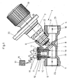
- the embodiment shown in Figure 1 for a Valve 1 according to the invention has for receiving sensor lances 12 two further nozzles 9, 10.
- the further nozzles 9, 10 point to pass through channels that have an inner cross section, the the outer cross section of the sensor lances 12 essentially equivalent.
- At the top is a plug 11 in above the channels the nozzle 9, 10 used.
- These plugs 11 made of an elastomer have an axially extending central hole through which the sensor lances 12 are inserted.
- the plugs 11 of the sockets 9, 10 are attached to the connecting piece 9, 10 by means of a union nut 24.
- the Sensor lances 12 are from the outside through central holes in the Union nuts 24 in the stopper 11 and on the stopper 11 subsequent channel inserted and protrude with their lower End out of the nozzle 9, 10 and into the room in front of the Valve seat 8 into it.
- a sensor 13, 14 At the lower ends, namely in the space in front of the valve seat 8 protruding ends of the sensor lances 12 is a sensor 13, 14 attached.
- the sensor signals are switched on via the sensor lances 12
- These are connected via cables calculation means arranged in a housing 16 connected, the housing 16 being designed as an operating device and therefore has a keyboard and display means 17.
- the volume flow that flows through the valve Liquid is measured using the calorimetric measuring principle Flow rate in the space in front of the body valve seat certainly.
- the Flow rate is the volume flow for the valve 1 assigned nominal size determined. This volume flow can then in can be read from the display means 17.
- the valve according to the invention has The illustrated embodiment only has a further nozzle 9 on.
- Sensors 13, 14 are provided, of which the sensor 14 is heated, according to the calorimetric measuring principle To be able to measure flow velocity in the housing 2.
- the Channel which receives the sensor lances 12, opens into one Region of the connecting piece 9, in which a plug 11 is inserted, which has two axially extending holes through which the sensor lances 12 are inserted.
- the plug 11 will secured by a union nut 24.
- a device for signal amplification 15 put on which via signal lines with a calculation means is connected in a housing 16.
- the housing 16 is like that Embodiment according to Figure 1 executed as a handheld device.
- FIG. 3 for a Valve 1 has the same as that shown in FIG Embodiment only a further nozzle 9.
- This Stub 9 contains like the embodiment shown in Figure 2 a channel.
- the channel flows down into the area in front of the Valve seat 8 and in the upper area in a widened space, in the nozzle 9, which is filled by a nozzle 11.
- the Plug 11 has a central hole, and plug 11 is secured by a union nut 24.
- the union nut 24 has also in the extension of the channel a recess.
- the axial, hole in the Plug 11 and the channel in the nozzle 9 is a sensor lance 12 introduced.
- the lower end of this sensor lance 12 projects into the Area in front of valve seat 8.
- the Sensor lance 12 At the bottom of the Sensor lance 12, two sensors 13, 14 are provided, of which the sensor 14 is heated according to the flow rate to be able to measure the calorimetric measuring principle. At the top The end of the sensor lance 12 is a device for signal amplification 15 is provided, which via signal lines with a housing 16 is connected, which is like the housing of the embodiments 1 and 2 is designed as a hand-held device.
- FIG. 4 The embodiment shown in Figure 4 for a Valve according to the invention is similar to that shown in Figure 3 Embodiment executed.
- nozzle 9 provided in which a channel is provided. Through this Channel is a sensor lance 12 inserted, which at its lower end protruding into the area in front of the valve seat 8 Has sensors 13, 14, of which the sensor 14 is heatable to according to the calorimetric measuring principle Flow velocity of those flowing in through the valve To be able to capture liquid.
- On the nozzle 9 is however in Difference to the embodiment shown in Figure 3 in a ball valve 25 in the exemplary embodiment shown in FIG. 4 screwed. Then on this ball valve 25 is also additional connector 26 screwed on. There is a seal in this 27 provided.
- Both the complementary nozzle 26 that is in it used seal 27, as well as the ball valve 25 in his open state extend the provided in the nozzle 9 Channel up.
- the open state of the Ball valve 25 can, however, a sensor lance 12 through the Supplementary nozzle 26 with the seal 27 arranged therein, the Ball valve 25 and the other nozzle 9 are inserted, the lower end of the sensor lance 12 in the area in front of the Valve seat 8 of housing 2 protrudes.
- two sensors 13, 14 are provided.
- At the upper end of the sensor lance is as in the embodiment in Figure 3 provides a device for signal amplification 15 on which then is that from the previous exemplary embodiments known housing 16 with calculation means and others connected.
- FIG. 5 for a Valve 1 The embodiment shown in Figure 5 for a Valve 1 according to the invention most closely corresponds to that in FIG. 1 illustrated embodiment.
- the two embodiments according to FIG. 1 and according to FIG. 5 differ only by the arrangement of the further nozzle 9, 10. While the other Neck in the embodiment of Figure 1 in axial Direction of the housing 2 are arranged on the second nozzle 5, are the other connecting pieces 9, 10 as shown in Figure 5a directly can be seen in the circumferential direction of the second nozzle 5 arranged side by side.
Landscapes
- Engineering & Computer Science (AREA)
- General Engineering & Computer Science (AREA)
- Physics & Mathematics (AREA)
- Fluid Mechanics (AREA)
- General Physics & Mathematics (AREA)
- Mechanical Engineering (AREA)
- Indication Of The Valve Opening Or Closing Status (AREA)
- Measuring Volume Flow (AREA)
Abstract
Description
- Fig. 1
- ein Ventil mit zwei weiteren Stutzen,
- Fig. 2
- ein Ventil mit einem Stutzen für zwei Sensorlanzen,
- Fig. 3, 3a
- ein Ventil mit einem Stutzen für eine Sensorlanze,
- Fig. 4
- einen Stutzen für eine Sensorlanze mit einem Kugelhahn zum Absperren des weiteren Stutzens und
- Fig. 5, 5a
- ein Ventil mit zwei in Umfangsrichtung hintereinanderliegenden Stutzen.
Claims (24)
- Ventil (1) für Flüssigkeiten zum Einbau in Leitungen, insbesondere Strangventil für Wasserversorgungseinrichtung, mit folgenden Merkmalen:dadurch gekennzeichnet, dass das Ventil (1) in einem Bereich, der strömungstechnisch vor oder hinter dem Ventilsitz (8) angeordnet ist, einen oder mehrere weitere Stutzen (9, 10) zum Anschluss von Sensoren (3, 14), zur Messung der Strömungsgeschwindigkeit nach dem kalorimetrischen Messprinzip aufweist, welche zur Messung der Strömungsgeschwindigkeit in das Ventil einsetzbar sind.das Ventil (1 ) weist ein Gehäuse (2) und ein Ventiloberteil (3) auf;das Gehäuse weist einen ersten Stutzen (4) zur Verbindung zur Leitung, einen zweiten Stutzen (5) zur Verbindung zur Leitung sowie einen dritten Stutzen (6) zur Aufnahme des Ventiloberteils (3) auf;das Ventil (1 ), insbesondere das Ventiloberteil (3), umfasst einen Ventilkegel (7);das Ventil (1), insbesondere das Gehäuse (2), umfasst einen Ventilsitz (8);der Ventilsitz (8) ist strömungstechnisch zwischen dem ersten Stutzen (4) und dem zweiten Stutzen (5) angeordnet und der Ventilsitz (8) wirkt zum Einstellen des Durchflusses mit dem Ventilkegel (7) zusammen;
- Ventil nach dem vorhergehenden Anspruch, dadurch gekennzeichnet, dass das Ventil (1 ) genau einen weiteren Stutzen (9, 10) zum Anschluss von Sensoren aufweist.
- Ventil nach einem der vorhergehenden Ansprüche, dadurch gekennzeichnet, dass in zumindest einem der weiteren Stutzen (9, 10) ein Ring oder eine Manschette aus einem Elastomer angeordnet ist.
- Ventil nach dem vorhergehenden Anspruch, dadurch gekennzeichnet, dass der Ring oder die Manschette in axialer/radialer Richtung des Rings beziehungsweise der Manschette eingespannt ist.
- Ventil nach einem der vorhergehenden Ansprüche, dadurch gekennzeichnet, dass in zumindest einem der weiteren Stutzen (9, 10) ein zumindest einfach axial gelochter Stopfen (11) aus einem Elastomer eingesetzt ist, wobei das Loch/des Stopfen im entspannten Zustand verschlossen ist.
- Ventil nach einem der vorhergehenden Ansprüche, dadurch gekennzeichnet, dass die weiteren Stutzen (9, 10) am ersten oder zweiten Stutzen (4, 5) angeordnet sind.
- Ventil nach dem vorhergehenden Anspruch, dadurch gekennzeichnet, dass die weiteren Stutzen (9, 10) in axialer Richtung des ersten oder zweiten Stutzens (4, 5) hintereinanderliegend angeordnet sind.
- Ventil nach Anspruch 6, dadurch gekennzeichnet, dass die weiteren Stutzen (9, 10) in Umfangsrichtung des ersten oder zweiten Stutzens (4, 5) nebeneinanderliegend angeordnet sind.
- Ventil nach einem der vorhergehenden Ansprüche, dadurch gekennzeichnet, dass in den weiteren Stutzen (4, 5) eine oder zwei Sensorlanzen (12) oder Sensornadeln entnehmbar eingesetzt sind.
- Ventil nach einem der vorhergehenden Ansprüche, dadurch gekennzeichnet, dass im Bereich der Spitze der Sensorlanzen (12) zumindest ein Temperatursensor (13, 14) eingesetzt ist.
- Ventil nach dem vorhergehenden Anspruch, dadurch gekennzeichnet, dass ein Teil der Temperatursensoren (13, 14) beheizt ist.
- Ventil nach dem Anspruch 10 oder 11, dadurch gekennzeichnet, dass die Temperatursensoren (13, 14) mit einer Einrichtung (15) zur Signalverstärkung verbunden sind.
- Ventil nach einem der Ansprüche 10 bis 12, dadurch gekennzeichnet, dass die Temperatursensoren (13, 14) mit einem Berechnungsmittel verbunden sind.
- Verfahren nach dem vorhergehenden Anspruch, dadurch gekennzeichnet, dass das Berechnungsmittel mit einem Anzeigemittel (17) verbunden ist.
- Ventil nach Anspruch 13 und 14, dadurch gekennzeichnet, dass das Berechnungsmittel und das Anzeigemittel (17) und vorteilhaft die Einrichtung zur Signalverstärkung in einem Gehäuse (16) angeordnet sind.
- Ventil nach Anspruch 13 oder 14 , dadurch gekennzeichnet, dass das Berechnungsmittel an der Sensorlanze angebracht ist.
- Ventil nach Anspruch 16, dadurch gekennzeichnet, dass das Berechnungsmittel an dem zu der Spitze entgegengesetzten Ende der Sensorlanze angebracht ist.
- Ventil nach Anspruch 16 oder 17, dadurch gekennzeichnet, dass das Berechnungsmittel ein Gehäuse umfasst, welches an der Sensorlanze (12) befestigt ist.
- Ventil nach einem der Ansprüche 13 bis 18, dadurch gekennzeichnet, dass das Berechnungsmittel elektronische Bauelemente umfasst.
- Ventil nach Anspruch 19, dadurch gekennzeichnet, dass die Bauelemente auf einem Schaltungsträger des Berechnungsmittels angeordnet sind.
- Ventil nach einem der Ansprüche 16 bis 20, dadurch gekennzeichnet, dass das Berechnungsmittel, außerhalb der Lanze liegt.
- Ventil nach einem der Ansprüche 9 bis 21, dadurch gekennzeichnet, dass die Sensorlanze (12) einen Durchmesser von ca. 4 mm hat.
- Sensor zur Messung der Strömungsgeschwindigkeit nach dem kalorimetrischen Messprinzip mit folgenden Merkmalen:die Sensorlanze weist eine Sensorlanze auf;die Sensorlanze (12) weist ein erstes Ende mit einer Spitze auf, in welcher zumindest zwei Temperatursensoren (13, 14) eingesetzt sind, von denen einer beheizt ist;die Sensorlanze weist ein zweites Ende auf, an dem ein Gehäuse angebracht ist;in dem Gehäuse sind elektrische Bauelemente angeordnet;der Sensor weist ein Berechnungsmittel auf, welches das Gehäuse und die elektrischen Bauelemente umfasst.
- Sensor nach Anspruch 23, dadurch gekennzeichnet, dass die Sensorlanze einen Durchmesser von ca. 4 mm hat.
Applications Claiming Priority (2)
| Application Number | Priority Date | Filing Date | Title |
|---|---|---|---|
| DE10238963 | 2002-08-20 | ||
| DE2002138963 DE10238963A1 (de) | 2002-08-20 | 2002-08-20 | Ventil insbesondere Strangventil |
Publications (2)
| Publication Number | Publication Date |
|---|---|
| EP1391646A2 true EP1391646A2 (de) | 2004-02-25 |
| EP1391646A3 EP1391646A3 (de) | 2005-03-02 |
Family
ID=30775551
Family Applications (1)
| Application Number | Title | Priority Date | Filing Date |
|---|---|---|---|
| EP03018833A Withdrawn EP1391646A3 (de) | 2002-08-20 | 2003-08-19 | Ventil |
Country Status (2)
| Country | Link |
|---|---|
| EP (1) | EP1391646A3 (de) |
| DE (1) | DE10238963A1 (de) |
Cited By (3)
| Publication number | Priority date | Publication date | Assignee | Title |
|---|---|---|---|---|
| WO2007145559A1 (en) * | 2006-06-12 | 2007-12-21 | Tour & Andersson Ab | Regulating valve with a maintained regulating characteristic at different kv-values within one and the same valve |
| WO2014044787A3 (de) * | 2012-09-22 | 2014-07-31 | Ksb Aktiengesellschaft | Strangregulierarmatur |
| RU2705657C1 (ru) * | 2018-03-16 | 2019-11-11 | Сименс Акциенгезелльшафт | Измерение потока в клапанах с термической коррекцией |
Families Citing this family (1)
| Publication number | Priority date | Publication date | Assignee | Title |
|---|---|---|---|---|
| DE102015120511A1 (de) * | 2015-11-26 | 2017-06-01 | Schell Gmbh & Co. Kg | Eckventil |
Family Cites Families (14)
| Publication number | Priority date | Publication date | Assignee | Title |
|---|---|---|---|---|
| GB1110157A (en) * | 1966-09-09 | 1968-04-18 | Tour Agenturer Ab | A fluid-flow control valve |
| DE3216613A1 (de) * | 1982-05-04 | 1983-11-10 | OEKON-Wärmetechnik GmbH, 4280 Borken | Kalorimetrisch-elektronisches messsystem zum messen von abgasgeschwindigkeiten |
| DE3432494C2 (de) * | 1984-09-04 | 1995-07-27 | Buerkert Gmbh | Regelungsanordnung zur Regelung des Durchsatzes von Gas- oder Flüssigkeitsströmen in Rohrleitungen |
| GB8620357D0 (en) * | 1986-08-21 | 1986-10-01 | Apv Int Ltd | Flow control valve |
| WO1991010852A1 (en) * | 1990-01-15 | 1991-07-25 | Tour & Andersson Ab | Apparatus for measurement and control, respectively, of temperature and/or pressure |
| CA2076667A1 (en) * | 1990-03-02 | 1991-09-03 | Alexandros D. Powers | Multiprobes with thermal diffusion flow monitor |
| US5251148A (en) * | 1990-06-01 | 1993-10-05 | Valtek, Inc. | Integrated process control valve |
| DE4426100C2 (de) * | 1994-07-22 | 1997-07-10 | Bosch Gmbh Robert | Vorrichtung zur Messung der Masse eines strömenden Mediums |
| DE19619125C2 (de) * | 1995-11-04 | 2001-12-13 | Gampper Gmbh | Ventil mit Voreinstellung der Durchflußmenge für einen Heizkörper einer Warmwasseranlage |
| DE29619628U1 (de) * | 1995-11-30 | 1997-04-10 | Hiss, Eckart, Dr., 24105 Kiel | Strömungsüberwachungsgerät |
| DE19600286C2 (de) * | 1996-01-05 | 2001-03-29 | Festo Ag & Co | Kompaktregelventil |
| DE29721502U1 (de) * | 1996-12-21 | 1998-04-23 | KSB AG, 67227 Frankenthal | Strangregulierarmatur |
| JP3285513B2 (ja) * | 1997-05-28 | 2002-05-27 | 三菱電機株式会社 | 感熱式流量センサおよび内燃機関の吸気装置 |
| DE10031813C2 (de) * | 2000-06-30 | 2002-08-01 | Fafnir Gmbh | Verfahren und Vorrichtung zum Bestimmen des Durchflusses eines Gasgemisches |
-
2002
- 2002-08-20 DE DE2002138963 patent/DE10238963A1/de not_active Withdrawn
-
2003
- 2003-08-19 EP EP03018833A patent/EP1391646A3/de not_active Withdrawn
Non-Patent Citations (1)
| Title |
|---|
| None * |
Cited By (4)
| Publication number | Priority date | Publication date | Assignee | Title |
|---|---|---|---|---|
| WO2007145559A1 (en) * | 2006-06-12 | 2007-12-21 | Tour & Andersson Ab | Regulating valve with a maintained regulating characteristic at different kv-values within one and the same valve |
| CN101466970B (zh) * | 2006-06-12 | 2010-12-15 | 图尔和安德森公司 | 在一个和相同阀中有在不同kv值的保持调节特征的调节阀 |
| WO2014044787A3 (de) * | 2012-09-22 | 2014-07-31 | Ksb Aktiengesellschaft | Strangregulierarmatur |
| RU2705657C1 (ru) * | 2018-03-16 | 2019-11-11 | Сименс Акциенгезелльшафт | Измерение потока в клапанах с термической коррекцией |
Also Published As
| Publication number | Publication date |
|---|---|
| EP1391646A3 (de) | 2005-03-02 |
| DE10238963A1 (de) | 2004-03-04 |
Similar Documents
| Publication | Publication Date | Title |
|---|---|---|
| DE2061978A1 (de) | Messwertgebereinrichtung mit herausnehmbarer Messwertgebersonde | |
| DE69717202T2 (de) | Absperrventil mit eingebauter Expansionsdüse für unter Druck stehende Umlaufmittel einer Heiz- und Kühlanlage von Luft | |
| EP0413198A1 (de) | Anordnung für die Messung der Temperatur einer eine Rohrleitung durchströmenden Flüssigkeit | |
| DE2916522A1 (de) | Abzweigvorrichtung | |
| DE19827992C2 (de) | Vorrichtung zum Verbinden einer Volumenstrom-Messeinrichtung mit einer flüssigkeitsführenden Rohrleitung | |
| DE4031789C2 (de) | ||
| DE3200587A1 (de) | "vorrichtung zum ermitteln von messgroessen in rohrleitungssystemen" | |
| EP2180226B1 (de) | Modulares Fluidverteilsystem | |
| WO2008019715A1 (de) | Vorrichtung zur überprüfung des reinigungs- und desinfektionsergebnisses bei insbesondere in waschautomaten gereinigten diagnostischen und chirurgischen instrumenten | |
| EP1391646A2 (de) | Ventil | |
| DE2557542C3 (de) | Meßeinrichtung für elektrische und/oder elektrometrische Werte strömender Medien | |
| DE202020102595U1 (de) | Fluidsystem | |
| DE4101733A1 (de) | Sicherheitseinsatz fuer druckgas und fluessiggas | |
| DE4030142C2 (de) | ||
| DE10114996B4 (de) | Vorrichtung zur Messung von Druck- und/oder Temperatur in einem fluidführenden Mediumkanal | |
| DE3800245C2 (de) | ||
| EP2076702B1 (de) | Durchflusseinstellventil | |
| DE4015107C2 (de) | ||
| DE4007276C2 (de) | Gas-Gebäudeanschlußvorrichtung | |
| EP0677722A2 (de) | Rohrleitungs-Pass-Stück, insbesondere für opto-elektronische Volumenstrom-Messungen in Rohrleitungen | |
| DE10201231B4 (de) | Vorrichtung und Verfahren zum Prüfen von Sanitärarmaturen | |
| DE3109350A1 (de) | Abflussschieber mit einem kolbenfoermigen, axial verschiebbaren absperrkoerper | |
| DE2501545C3 (de) | Verteiler für Vor- und Rücklauf an einem Heizungskessel | |
| DE4030104A1 (de) | Strangregulierventil | |
| DE4309450A1 (en) | Leak testing device for pressurised lines, esp. for gas - has pre-testing and main testing devices, water container with column indicator, air pump, and couplings with automatic valves |
Legal Events
| Date | Code | Title | Description |
|---|---|---|---|
| PUAI | Public reference made under article 153(3) epc to a published international application that has entered the european phase |
Free format text: ORIGINAL CODE: 0009012 |
|
| AK | Designated contracting states |
Kind code of ref document: A2 Designated state(s): AT BE BG CH CY CZ DE DK EE ES FI FR GB GR HU IE IT LI LU MC NL PT RO SE SI SK TR |
|
| AX | Request for extension of the european patent |
Extension state: AL LT LV MK |
|
| PUAL | Search report despatched |
Free format text: ORIGINAL CODE: 0009013 |
|
| AK | Designated contracting states |
Kind code of ref document: A3 Designated state(s): AT BE BG CH CY CZ DE DK EE ES FI FR GB GR HU IE IT LI LU MC NL PT RO SE SI SK TR |
|
| AX | Request for extension of the european patent |
Extension state: AL LT LV MK |
|
| RAP1 | Party data changed (applicant data changed or rights of an application transferred) |
Owner name: HONEYWELL TECHNOLOGIES SARL |
|
| 17P | Request for examination filed |
Effective date: 20050818 |
|
| AKX | Designation fees paid |
Designated state(s): AT BE BG CH CY CZ DE DK EE ES FI FR GB GR HU IE IT LI LU MC NL PT RO SE SI SK TR |
|
| 17Q | First examination report despatched |
Effective date: 20051118 |
|
| STAA | Information on the status of an ep patent application or granted ep patent |
Free format text: STATUS: THE APPLICATION IS DEEMED TO BE WITHDRAWN |
|
| 18D | Application deemed to be withdrawn |
Effective date: 20070619 |