EP1391653A2 - Système d'injection de carburant - Google Patents
Système d'injection de carburant Download PDFInfo
- Publication number
- EP1391653A2 EP1391653A2 EP03254684A EP03254684A EP1391653A2 EP 1391653 A2 EP1391653 A2 EP 1391653A2 EP 03254684 A EP03254684 A EP 03254684A EP 03254684 A EP03254684 A EP 03254684A EP 1391653 A2 EP1391653 A2 EP 1391653A2
- Authority
- EP
- European Patent Office
- Prior art keywords
- prefilmer
- fuel injection
- injection arrangement
- fuel
- fluid flow
- Prior art date
- Legal status (The legal status is an assumption and is not a legal conclusion. Google has not performed a legal analysis and makes no representation as to the accuracy of the status listed.)
- Withdrawn
Links
Images

Classifications
-
- F—MECHANICAL ENGINEERING; LIGHTING; HEATING; WEAPONS; BLASTING
- F23—COMBUSTION APPARATUS; COMBUSTION PROCESSES
- F23D—BURNERS
- F23D11/00—Burners using a direct spraying action of liquid droplets or vaporised liquid into the combustion space
- F23D11/10—Burners using a direct spraying action of liquid droplets or vaporised liquid into the combustion space the spraying being induced by a gaseous medium, e.g. water vapour
- F23D11/106—Burners using a direct spraying action of liquid droplets or vaporised liquid into the combustion space the spraying being induced by a gaseous medium, e.g. water vapour medium and fuel meeting at the burner outlet
- F23D11/107—Burners using a direct spraying action of liquid droplets or vaporised liquid into the combustion space the spraying being induced by a gaseous medium, e.g. water vapour medium and fuel meeting at the burner outlet at least one of both being subjected to a swirling motion
-
- F—MECHANICAL ENGINEERING; LIGHTING; HEATING; WEAPONS; BLASTING
- F23—COMBUSTION APPARATUS; COMBUSTION PROCESSES
- F23D—BURNERS
- F23D11/00—Burners using a direct spraying action of liquid droplets or vaporised liquid into the combustion space
- F23D11/36—Details
- F23D11/38—Nozzles; Cleaning devices therefor
-
- F—MECHANICAL ENGINEERING; LIGHTING; HEATING; WEAPONS; BLASTING
- F23—COMBUSTION APPARATUS; COMBUSTION PROCESSES
- F23D—BURNERS
- F23D2210/00—Noise abatement
-
- F—MECHANICAL ENGINEERING; LIGHTING; HEATING; WEAPONS; BLASTING
- F23—COMBUSTION APPARATUS; COMBUSTION PROCESSES
- F23D—BURNERS
- F23D2900/00—Special features of, or arrangements for burners using fluid fuels or solid fuels suspended in a carrier gas
- F23D2900/11101—Pulverising gas flow impinging on fuel from pre-filming surface, e.g. lip atomizers
-
- F—MECHANICAL ENGINEERING; LIGHTING; HEATING; WEAPONS; BLASTING
- F23—COMBUSTION APPARATUS; COMBUSTION PROCESSES
- F23R—GENERATING COMBUSTION PRODUCTS OF HIGH PRESSURE OR HIGH VELOCITY, e.g. GAS-TURBINE COMBUSTION CHAMBERS
- F23R2900/00—Special features of, or arrangements for continuous combustion chambers; Combustion processes therefor
- F23R2900/00014—Reducing thermo-acoustic vibrations by passive means, e.g. by Helmholtz resonators
Definitions
- the present invention relates to a fuel injection arrangement for a combustor of a gas turbine engine and in particular a prefilmer for the fuel injection arrangement.
- a preferred lean direct injector is disclosed in US6,272,840.
- This injector comprises a pilot injector surrounded by a coaxial main injector.
- the pilot injector provides a pilot flame that has a relatively high, but stable fuel/air ratio.
- the main injector provides a main flame that has a lean fuel/air ratio.
- the main injector supplies the majority of the combustion gases above low power so that low levels of oxides of nitrogen (NOx) emissions are obtained because the main injector produces a uniformly mixed fuel-air mixture at an equivalence ratio less than stoichiometric. This mixture burns at a relatively low flame temperature avoiding the NOx producing high temperature volumes of more conventional combustion systems.
- NOx oxides of nitrogen
- a prefilmer is mounted between radially adjacent swirl vanes. Fuel is shed from the downstream edge of the prefilmer, and is atomised as it passes through a shear region formed by the swirl vanes. In a typical lean burn fuel injector this is the only purpose of the prefilmer.
- an object of the present invention is to provide a means for reducing combustion instability and in particular reducing net heat release fluctuations within the combustor.
- the present invention seeks to provide a prefilmer for a fuel injection arrangement comprising a body having a fluid flow surface and a downstream edge, the prefilmer arranged so that when working in operative association with the fuel injection arrangement fuel flows over the surface, by means of a passing airflow, to the downstream edge, from where the fuel is shed, characterised in that the prefilmer further comprises a fluid flow mixing means to, in use, enhance the mixing of fuel and air.
- the fluid flow mixing means comprises projections extending generally downstream from the downstream edge; the projections are generally trapezoidal in shape. Alternatively, the projections are generally triangular in shape.
- the projections define trapezoidal notches therebetween, but alternatively the notches are triangular.
- the projections are radially inwardly angled.
- the projections are radially outwardly angled and furthermore the projections are alternately radially inwardly and outwardly angled. It is preferred that the angle of the projections is between 0 and 45 degrees relative to an injector axis.
- the fluid flow mixing means comprises the downstream edge configured in a generally sinusoidal form in its axial direction or alternatively in its radial direction.
- the fluid flow mixing means comprises lands disposed to the downstream edge, the lands are configured to generate and impart, in use, vortices into the passing airflow to enhance the mixing of fuel and air.
- the lands comprise a leading edge, two opposing sides, a leeward face and a base attached to the fluid flow surface.
- the fluid flow mixing means is asymmetrically arranged about the prefilmer.
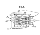
- Figure 1 is a schematic section of a ducted fan gas turbine engine incorporating an embodiment of the present invention.
- Figure 2 is a sectioned schematic view of a first embodiment for a piloted airblast lean direct fuel injector incorporating a first embodiment of a fluid flow mixing means in accordance with the present invention.
- Figure 2a is an illustrative enlarged perspective view of the fluid flow mixing means shown in Figure 2.
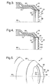
- Figure 3 shows a second embodiment of the fluid flow mixing means in accordance with the present invention.
- Figure 4 shows a third embodiment of the fluid flow mixing means in accordance with the present invention.
- Figure 5 is a perspective view of a fourth embodiment of the fluid flow mixing means in accordance with the present invention.
- a ducted fan gas turbine engine 110 comprises, in axial flow series an air intake 112, a propulsive fan 114, a core engine 116 and an exhaust nozzle assembly 118 all disposed about a central engine axis 120.
- the core engine 116 comprises, in axial flow series, a series of compressors 122, a combustor 124, and a series of turbines 126.
- the direction of airflow through the engine 110 in operation is shown by arrow A. Air is drawn in through the air intake 112 and is compressed and accelerated by the fan 114. The air from the fan 114 is split between a core engine flow and a bypass flow.
- the core engine flow passes through an annular array of stator vanes 128 and enters core engine 116, flows through the core engine compressors 122 where it is further compressed, and into the combustor 124 where it is mixed with fuel, which is supplied to, and burnt within the combustor 124.
- Combustion of the fuel mixed with the compressed air from the compressors 122 generates a high energy and velocity gas stream that exits the combustor 124 and flows downstream through the turbines 126.
- the high energy gas stream flows through the turbines 126 it rotates turbine rotors extracting energy from the gas stream which is used to drive the fan 114 and compressors 122 via engine shafts 130 which drivingly connect the turbine 126 rotors with the compressors 122 and fan 114.
- the high energy gas stream from the combustor 122 still has a significant amount of energy and velocity and it is exhausted, as a core exhaust stream, through the engine exhaust nozzle assembly 118 to provide propulsive thrust.
- the remainder of the air from, and accelerated by, the fan 114 flows through an annular array of guide vanes 132 within a bypass duct 134 around the core engine 116.
- This bypass airflow which has been accelerated by the fan 114, flows to the exhaust nozzle assembly 118 where it is exhausted, as a bypass exhaust stream to provide further, and in fact the majority of, the useful propulsive thrust.
- the combustor 124 incorporates a fuel injection arrangement (not shown), which is in accordance with the present invention.
- the fuel injection arrangement suitable for a gas turbine engine is generally indicated at 60.
- the fuel injection arrangement 60 is attached to the upstream end of a gas turbine engine combustion chamber 11, part of which can be seen in Figure 2.
- the terms "upstream” and “downstream” are used with respect to the general direction of a flow of liquid and gaseous materials through the fuel injection arrangement 60 and the combustion chamber 11 as shown by arrow A.
- the upstream end is towards the left hand side of the drawing and the downstream end is towards the right hand side.
- the actual configuration of the combustion chamber 11 is conventional and will not, therefore, be described in detail.
- the combustion chamber 11 may be of the well known annular type or alternatively of the cannular type so that it is one of an annular array of similar individual combustion chambers or cans.
- one fuel injection arrangement 60 would normally be provided for each combustion chamber 11.
- the single chamber would be provided with a plurality of fuel injection arrangement 60 arranged in an annular array at its upstream end.
- more than one such annular array could be provided if so desired. For instance, there could be two coaxial arrays.
- FIG. 2 shows a prior art piloted airblast lean direct fuel injector arrangement 60, which is described in detail in US6,272,840, the teachings of which are incorporated herein by reference. However, the main features are briefly described where particularly relevant to the present invention.
- the injector arrangement 60 is generally annular and symmetrical about an injector axis 62 and is disposed at the upstream end of the combustion chamber 11.
- the fuel injector arrangement 60 comprises a pilot or primary injector 12 and a pilot swirler 14 generally surrounding the pilot injector 12.
- a main airblast fuel or secondary injector 16 is concentrically positioned around the pilot injector 12 and inner and outer main swirlers 18, 20 are concentrically disposed radially inwardly and outwardly respectively of the main airblast fuel injector 16.
- An annular air splitter 22 is located between the pilot swirler 14 and the inner main swirler 18.
- the air splitter 22 comprises an air inlet 24 and downstream, an air outlet 26.
- the air splitter 22, in the direction of air flow, further comprises a generally cylindrical portion 28, a radially inwardly tapered portion 30 and a downstream portion 32 that is tapered still further radially inwardly.
- annular and co-axial members 68, 70 and 72, 74 are defined by annular and co-axial members 68, 70 and 72, 74, of the main and pilot fuel injectors 16 and 12 respectively.
- the annular members 68 and 72 are fuel prefilmers having surfaces 80, 82 that the fuel flows over prior to being shed from downstream edges 44, 45 into the swirling airflows.
- the geometry and position of the air splitter 22 is such that it separates the air flow exiting the pilot injector 12 and the main injector 16 thereby creating a bifurcated recirculation zone between the pilot and main air flows.
- the creation of the bifurcated recirculation zone, that aerodynamically separates the pilot flame from the main flame, benefits the lean blowout stability of the fuel injector arrangement 60.
- the pilot fuel stays nearer to the injector axis 62 and evaporates there, thus providing a richer burning zone for the pilot flame than is the case for the main flame.
- the fuel/air ratio for the pilot flame remains significantly richer than that for the main flame over a wide range of operating conditions.
- the main injector supplies the majority of the combustion gases at most engine operating conditions, so that low levels of oxides of nitrogen (NOx) emissions are obtained because the main injector produces a uniformly mixed fuel-air mixture at an equivalence ratio less than stoichiometric. This mixture burns at a relatively low flame temperature avoiding the NOx producing high temperature volumes of more conventional combustion systems.
- NOx oxides of nitrogen
- combustion systems such as the prior art device described above, can produce NOx emissions levels significantly lower than conventional combustion systems, they have severe disadvantages. One of these is combustion instability.
- downstream edges 44, 45 comprise fluid flow mixing means 34 in accordance with a first embodiment of the present invention.
- Figure 2a shows the fluid flow mixing means 34 as an array of lands 84 disposed around the inner circumference of the prefilmer 68 near to the downstream edge 44.
- the lands 84 enhance mixing the fuel and air by generating vortices, shown by the sequence of arrows 86, which breaks up the fuel into yet smaller particles. The smaller the particle size of the fuel, the greater the surface area of a given fuel quantity and therefore the quicker it is vaporised.
- the lands 84 are four sided and comprise a leading edge 88, two opposing sides 90, a leeward face 92 and a base attached to the prefilmer 68. Air flowing in the direction of arrow B flows over the edge between a side 90 and the leeward face 92 and in so doing a vortex is imparted into the air flow as shown by arrows 86.
- the lands 84 are generally orientated parallel to the injector main axis 62.
- lands 84 may be used but they do not depart from the scope or spirit of the present invention if they produce vortices which enhance the mixing of the air and fuel fluid flow.
- the size, positioning and number may be altered to suit each particular application.
- the orientation of the lands 84 may be altered so that for instance a land axis 36 is orientated in the general direction of the swirling air flow; the direction of the swirling airflow may not necessarily be aligned with the injector axis 62.
- the fuel is discharged onto a radially outer surface 81 or 83 of the prefilmers of the main injector 16 or pilot injector 12.
- the fluid flow mixing means 34 is disposed to the radially outer surfaces 81, 83 and operates in a similar fashion to the foregoing embodiment.
- FIG. 3 shows a second embodiment of a main injector 16 in accordance with the present invention, although this embodiment is equally applicable to the pilot injector 12.
- the annular members 68, 70 are shown and like reference numerals are used for like elements throughout the description of the present invention.
- the annular members 68, 70, of the main injector 16 are generally annular having a downstream edge portion 44 which itself comprises a fluid flow mixing means 34.
- Each fluid flow mixing means 34 is designed to impart mixing vortices into the fluid flow thereby enhancing the mixing of fluid flowing therepassed and consequently improving the fuel/air mixture ingressing to the combustion chamber 11.
- the main injector 16 in accordance with the present invention, continues to function in a conventional manner as described hereinbefore.
- fuel flows through the passageway between annular members 68, 70, through the orifice 76 and across the fluid flow surface 80.
- the fuel runs over the surface 80 and is shed from its downstream edge 44.
- the purpose of introducing a fluid flow mixing means 34 is to further break up the liquid fuel into a smaller particle size. By doing so the surface area of a particular quantity of fuel is increased which intrinsically increases the rate that the fuel is vaporised.
- the main injector 16 and indeed the pilot injector 12, is intended to be an alternative to the injectors 16 and 12 shown and described with reference to Figures 2 and 2a.
- the downstream edge 44 of the main injector 16 comprises an array of generally trapezoidal shaped projections 48, substantially aligned with and generally extending in the downstream direction of the injector axis 41, and which taper in the downstream direction.
- the projections 48 are equally spaced around the circumference of the main injector 16.
- the projections 48 may be spaced unequally around the circumference of the downstream edge 44.
- FIG 4 shows a third embodiment of a main injector 16 in accordance with the present invention, again this embodiment is equally applicable to the pilot injector 12.
- the annular members 68, 70 are shown and like reference numerals are used for like elements in Figure 2.
- the annular members 68, 70, of the main injector 16 are generally annular having a downstream edge portion 44 which itself comprises a fluid flow mixing means 34.
- Each fluid flow mixing means 34 is designed to impart mixing vortices into the fluid flow thereby enhancing the mixing of fluid flowing therepassed and consequently improving the fuel/air mixture ingressing to the combustion chamber 11.
- the downstream edge 44 of the main injector 16 comprises an array of generally triangular shaped projections 52, the apex of each being downstream.
- Each projection 52 is equally spaced around the circumference of the main injector 16 and is radially inwardly angled.
- the projections 52 are angled at approximately 45 0 , relative to the axis 62, and are generally aligned with the taper angle of a radially outer surface 81 of the annular member 68.
- an angle of 45 0 is shown the invention may be practised if the projections are within the range 0-45 0 .
- angles up to 90 0 relative to the injector axis 62 would also provide the desired generation of air/fuel mixing vortices.
- the projections 48, 52 are formed by laser or electro-discharge cutting V-shaped or trapezoidal shaped notches 50, 54 from a main injector 16 initially having a planar downstream edge. Therefore the projections 48, 52 are curved along their circumferentially length. Although the projections are shown as straight (in the axial direction), they may also be curved either radially inwardly or outwardly in the axial direction. It should be appreciated that the size, angle and circumferential positioning of the projections are dependant on each particular application and a general design philosophy dictates that a compromise exists between the amount and strength of vortices generated and the degree of fluid stream energy losses encountered.
- Figures 3 and 4 refer preferentially to trapezoidal and triangular shaped projections 48, 52 the skilled artisan may implement other shaped projections without departing from the scope and spirit of the present invention.
- Other suitable shapes for the projections comprise quadrilateral, polygonal or semi-circular or generally arcuate projections.
- the projections 48 may be alternately angled radially inwardly and outwardly thereby imparting vortices within either the radially inward or outward fluid flows passing through the inner and outer main swirlers 18, 20.
- Figure 5 shows a fourth embodiment of the present invention comprising the downstream edge 44 (or 45) arranged in a generally sinusoidal form in its axial direction, i.e. a peak 56 is downstream of a trough 58.
- the sinusoidal shaped downstream edge 44 directs portions of the fluid flows that pass radially inward or outward of the main injector 12, into one another thereby promoting mixing of the two fluid flows.
- the radial height difference between the peaks 56 and troughs 58 may be varied depending on each particular application, as may the number of peaks 56 and troughs 58 around the circumference of the downstream edge 44.
- the sinusoidal form is substantially in the radial direction so that the peaks 56 are radially outward of the troughs 58. This promotes forced mixing between radial inner and outer swirling airflows and therefore enhances the amount of mixing of the fuel and air fluid flow.
- downstream edge 44 may comprise a compound shape that is substantially sinusoidal in shape in both the axial and radial directions.
- the fluid flow mixing means 34 may also be disposed to any downstream edge of a fuel injector where only air flow over. This enhances the mixing capability of that air flow where it coalesces with a fluid flow comprising fuel liquid of vapour.
- a further advantage of the present invention and particularly associated to Figures 3,4 and 5 is that at low fuel flows the downstream edge of the prefilmers 68 create "streakiness" in the fuel flow flowing off the downstream edge. Low fuel flows are used at low engine power and at low power ignition. The streakiness of the fuel film coming off the downstream edge is relates to a variation in fuel film thickness associated with the shape of the downstream edge. For embodiments shown in Figures 3 and 4, where the fuel flow leaves the downstream edge near the apex of a notch 50, 54 there is a thicker fuel film than near the apex of the projections 48, 52.
- a circumferential array of shallow, radial channels may extend from the fuel gallery to the downstream edge.
- the prefilmer 68 therefore provides a fluid flow mixing means to, in use, enhance the mixing of fuel and air.
Landscapes
- Engineering & Computer Science (AREA)
- Chemical & Material Sciences (AREA)
- Combustion & Propulsion (AREA)
- Mechanical Engineering (AREA)
- General Engineering & Computer Science (AREA)
- Fuel-Injection Apparatus (AREA)
Applications Claiming Priority (2)
| Application Number | Priority Date | Filing Date | Title |
|---|---|---|---|
| GB0219461 | 2002-08-21 | ||
| GBGB0219461.1A GB0219461D0 (en) | 2002-08-21 | 2002-08-21 | Fuel injection arrangement |
Publications (2)
| Publication Number | Publication Date |
|---|---|
| EP1391653A2 true EP1391653A2 (fr) | 2004-02-25 |
| EP1391653A3 EP1391653A3 (fr) | 2005-05-04 |
Family
ID=9942709
Family Applications (1)
| Application Number | Title | Priority Date | Filing Date |
|---|---|---|---|
| EP03254684A Withdrawn EP1391653A3 (fr) | 2002-08-21 | 2003-07-26 | Système d'injection de carburant |
Country Status (3)
| Country | Link |
|---|---|
| US (1) | US20050097889A1 (fr) |
| EP (1) | EP1391653A3 (fr) |
| GB (1) | GB0219461D0 (fr) |
Cited By (20)
| Publication number | Priority date | Publication date | Assignee | Title |
|---|---|---|---|---|
| EP1801504A3 (fr) * | 2005-12-22 | 2010-08-04 | Rolls-Royce Deutschland Ltd & Co KG | Brûleur de prémélange maigre pourvu d'une lèvre de diffuseur |
| EP2549183A1 (fr) * | 2011-07-20 | 2013-01-23 | Rolls-Royce plc | Injecteur de carburant |
| CN102901099A (zh) * | 2012-09-14 | 2013-01-30 | 华中科技大学 | 一种花瓣式燃烧器 |
| US20130032639A1 (en) * | 2011-08-04 | 2013-02-07 | Rolls-Royce Plc | Fuel injector |
| EP2629011A1 (fr) * | 2008-09-29 | 2013-08-21 | Siemens Aktiengesellschaft | Buse de combustible |
| FR3029271A1 (fr) * | 2014-11-28 | 2016-06-03 | Snecma | Paroi annulaire de deflection pour systeme d'injection de chambre de combustion de turbomachine offrant une zone etendue d'atomisation de carburant |
| EP3118519A1 (fr) * | 2015-07-09 | 2017-01-18 | Rolls-Royce plc | Injecteur de carburant |
| EP2505808A3 (fr) * | 2011-03-28 | 2017-04-26 | Rolls-Royce Deutschland Ltd & Co KG | Dispositif de mélange de carburant et d'air dans un moteur à réaction |
| WO2017187104A1 (fr) * | 2016-04-28 | 2017-11-02 | Safran Aircraft Engines | Vrille d'admission d'air pour système d'injection de turbomachine comprenant un déflecteur aérodynamique à son entrée |
| WO2017218217A1 (fr) * | 2016-06-03 | 2017-12-21 | General Electric Company | Ensemble injecteur de carburant à pré-mélange tourbillonnant à enveloppe profilée |
| EP3447387A1 (fr) * | 2017-08-21 | 2019-02-27 | General Electric Company | Mélangeur non uniforme pour l'atténuation de la dynamique de combustion |
| EP3531021A1 (fr) * | 2018-02-23 | 2019-08-28 | Rolls-Royce plc | Conduit |
| EP3667169A1 (fr) * | 2018-12-12 | 2020-06-17 | Rolls-Royce plc | Buse de pulvérisation de carburant |
| US10935245B2 (en) | 2018-11-20 | 2021-03-02 | General Electric Company | Annular concentric fuel nozzle assembly with annular depression and radial inlet ports |
| US11073114B2 (en) | 2018-12-12 | 2021-07-27 | General Electric Company | Fuel injector assembly for a heat engine |
| US11156360B2 (en) | 2019-02-18 | 2021-10-26 | General Electric Company | Fuel nozzle assembly |
| US11286884B2 (en) | 2018-12-12 | 2022-03-29 | General Electric Company | Combustion section and fuel injector assembly for a heat engine |
| DE102024003163A1 (de) | 2024-09-27 | 2026-04-02 | Mercedes-Benz Group AG | Brenner für ein Kraftfahrzeug sowie Kraftfahrzeug |
| DE102024003159A1 (de) | 2024-09-27 | 2026-04-02 | Mercedes-Benz Group AG | Brenner für ein Kraftfahrzeug sowie Kraftfahrzeug |
| DE102024003162A1 (de) | 2024-09-27 | 2026-04-02 | Mercedes-Benz Group AG | Brenner für ein Kraftfahrzeug sowie Kraftfahrzeug |
Families Citing this family (54)
| Publication number | Priority date | Publication date | Assignee | Title |
|---|---|---|---|---|
| US7779636B2 (en) * | 2005-05-04 | 2010-08-24 | Delavan Inc | Lean direct injection atomizer for gas turbine engines |
| US7513098B2 (en) * | 2005-06-29 | 2009-04-07 | Siemens Energy, Inc. | Swirler assembly and combinations of same in gas turbine engine combustors |
| GB2439097B (en) * | 2006-06-15 | 2008-10-29 | Rolls Royce Plc | Fuel injector |
| DE102006032429A1 (de) * | 2006-07-13 | 2008-02-21 | Rolls-Royce Deutschland Ltd & Co Kg | Kraftstoffeinspritzvorrichtung für eine Fluggasturbine |
| US7762072B2 (en) * | 2007-01-16 | 2010-07-27 | Honeywell International Inc. | Combustion systems with rotary fuel slingers |
| JP4364911B2 (ja) * | 2007-02-15 | 2009-11-18 | 川崎重工業株式会社 | ガスタービンエンジンの燃焼器 |
| DE102007043626A1 (de) | 2007-09-13 | 2009-03-19 | Rolls-Royce Deutschland Ltd & Co Kg | Gasturbinenmagerbrenner mit Kraftstoffdüse mit kontrollierter Kraftstoffinhomogenität |
| DE102007050276A1 (de) * | 2007-10-18 | 2009-04-23 | Rolls-Royce Deutschland Ltd & Co Kg | Magervormischbrenner für ein Gasturbinentriebwerk |
| US8607571B2 (en) * | 2009-09-18 | 2013-12-17 | Delavan Inc | Lean burn injectors having a main fuel circuit and one of multiple pilot fuel circuits with prefiliming air-blast atomizers |
| GB0812905D0 (en) * | 2008-07-16 | 2008-08-20 | Rolls Royce Plc | Fuel injection system |
| EP2169307A1 (fr) * | 2008-09-29 | 2010-03-31 | Siemens Aktiengesellschaft | Buse à combustible |
| GB0820560D0 (en) * | 2008-11-11 | 2008-12-17 | Rolls Royce Plc | Fuel injector |
| US8453454B2 (en) * | 2010-04-14 | 2013-06-04 | General Electric Company | Coannular oil injection nozzle |
| US9435537B2 (en) * | 2010-11-30 | 2016-09-06 | General Electric Company | System and method for premixer wake and vortex filling for enhanced flame-holding resistance |
| JP5773342B2 (ja) * | 2011-06-03 | 2015-09-02 | 川崎重工業株式会社 | 燃料噴射装置 |
| JP5772245B2 (ja) | 2011-06-03 | 2015-09-02 | 川崎重工業株式会社 | 燃料噴射装置 |
| CN103649642B (zh) * | 2011-06-30 | 2016-05-04 | 通用电气公司 | 燃烧器及向燃烧器供应燃料的方法 |
| US9429325B2 (en) | 2011-06-30 | 2016-08-30 | General Electric Company | Combustor and method of supplying fuel to the combustor |
| US9423137B2 (en) * | 2011-12-29 | 2016-08-23 | Rolls-Royce Corporation | Fuel injector with first and second converging fuel-air passages |
| US9170024B2 (en) | 2012-01-06 | 2015-10-27 | General Electric Company | System and method for supplying a working fluid to a combustor |
| US9188337B2 (en) | 2012-01-13 | 2015-11-17 | General Electric Company | System and method for supplying a working fluid to a combustor via a non-uniform distribution manifold |
| US9097424B2 (en) | 2012-03-12 | 2015-08-04 | General Electric Company | System for supplying a fuel and working fluid mixture to a combustor |
| US9151500B2 (en) * | 2012-03-15 | 2015-10-06 | General Electric Company | System for supplying a fuel and a working fluid through a liner to a combustion chamber |
| US9052115B2 (en) | 2012-04-25 | 2015-06-09 | General Electric Company | System and method for supplying a working fluid to a combustor |
| US9284888B2 (en) | 2012-04-25 | 2016-03-15 | General Electric Company | System for supplying fuel to late-lean fuel injectors of a combustor |
| US8677753B2 (en) | 2012-05-08 | 2014-03-25 | General Electric Company | System for supplying a working fluid to a combustor |
| EP2923150B1 (fr) * | 2012-11-21 | 2018-09-05 | General Electric Company | Cartouche de combustible liquide anti-cokage |
| US20140144152A1 (en) * | 2012-11-26 | 2014-05-29 | General Electric Company | Premixer With Fuel Tubes Having Chevron Outlets |
| US20140144141A1 (en) * | 2012-11-26 | 2014-05-29 | General Electric Company | Premixer with diluent fluid and fuel tubes having chevron outlets |
| US20150285502A1 (en) * | 2014-04-08 | 2015-10-08 | General Electric Company | Fuel nozzle shroud and method of manufacturing the shroud |
| US20160061452A1 (en) * | 2014-08-26 | 2016-03-03 | General Electric Company | Corrugated cyclone mixer assembly to facilitate reduced nox emissions and improve operability in a combustor system |
| JP6623485B2 (ja) * | 2014-09-25 | 2019-12-25 | 三菱日立パワーシステムズ株式会社 | 燃焼器、及びこれを備えるガスタービン |
| US10317083B2 (en) * | 2014-10-03 | 2019-06-11 | Pratt & Whitney Canada Corp. | Fuel nozzle |
| WO2016068922A1 (fr) * | 2014-10-30 | 2016-05-06 | Siemens Aktiengesellschaft | Veilleuse et procédé pour la stabilisation d'une flamme de veilleuse dans une chambre de combustion soumise à une dynamique de combustion |
| FR3029608B1 (fr) * | 2014-12-03 | 2017-01-13 | Snecma | Couronne d'admission d'air pour systeme d'injection de chambre de combustion de turbomachine et procede d'atomisation de carburant dans un systeme d'injection comprenant ladite couronne d'admission d'air |
| US9863638B2 (en) * | 2015-04-01 | 2018-01-09 | Delavan Inc. | Air shrouds with improved air wiping |
| KR101657535B1 (ko) * | 2015-05-21 | 2016-09-19 | 두산중공업 주식회사 | 버닝 저감 연료공급노즐. |
| CN106016358B (zh) * | 2016-05-30 | 2019-04-30 | 中国科学院工程热物理研究所 | 一种兼具旋流、喷射与掺混作用的旋流器 |
| CN106091008B (zh) * | 2016-06-13 | 2019-08-02 | 中国科学院工程热物理研究所 | 兼具旋流、雾化与掺混作用的旋流器和喷射装置 |
| PL230047B1 (pl) * | 2016-07-06 | 2018-09-28 | Metal Expert Spolka Z Ograniczona Odpowiedzialnoscia Spolka Jawna | Palnik gazowy wysokotemperaturowy |
| GB2568981A (en) * | 2017-12-01 | 2019-06-05 | Rolls Royce Plc | Fuel spray nozzle |
| USD910717S1 (en) | 2018-07-31 | 2021-02-16 | Hotstart, Inc. | Rotary atomizer |
| US20200041130A1 (en) | 2018-07-31 | 2020-02-06 | Hotstart, Inc. | Combustor Systems |
| FR3095499B1 (fr) * | 2019-04-23 | 2021-06-11 | Safran Helicopter Engines | Injecteur d’un melange d’air et de carburant pour une chambre de combustion d’une turbomachine |
| US11371709B2 (en) | 2020-06-30 | 2022-06-28 | General Electric Company | Combustor air flow path |
| CN115711176B (zh) * | 2021-08-23 | 2025-09-05 | 通用电气公司 | 具有集成喇叭形旋流器的圆顶 |
| US12025311B2 (en) * | 2021-08-24 | 2024-07-02 | Solar Turbines Incorporated | Micromix fuel injection air nozzles |
| DE102022201182A1 (de) | 2022-02-04 | 2023-08-10 | Rolls-Royce Deutschland Ltd & Co Kg | Düsenbaugruppe mit eine Kraftstoffleitung passierender Verbindungsleitung in einem Düsenhauptkörper für eine Luftströmung |
| GB202214153D0 (en) | 2022-09-28 | 2022-11-09 | Rolls Royce Plc | Modulated heat management for geared gas turbine engines |
| GB202214148D0 (en) | 2022-09-28 | 2022-11-09 | Rolls Royce Plc | Gas turbine engine with improved heat management |
| GB202214143D0 (en) | 2022-09-28 | 2022-11-09 | Rolls Royce Plc | Gas turbine engine with an improved thermal management system |
| US12007115B1 (en) * | 2023-02-28 | 2024-06-11 | Rtx Corporation | High shear swirler for gas turbine engine |
| US12416407B2 (en) | 2024-02-15 | 2025-09-16 | Collins Engine Nozzles, Inc. | Combustor assembly including a fuel injection system for a turbomachine |
| EP4675177A1 (fr) * | 2024-07-01 | 2026-01-07 | RTX Corporation | Tube de prémélange avec atomisation de film de carburant pour un mélangeur principal étagé dans une chambre de combustion annulaire étagée axialement |
Citations (2)
| Publication number | Priority date | Publication date | Assignee | Title |
|---|---|---|---|---|
| EP0575254A1 (fr) | 1992-06-19 | 1993-12-22 | Total Raffinage Distribution S.A. | Procédé et dispositif de pulvérisation d'un liquide à l'aide d'au moins un fluide auxiliaire |
| US6272840B1 (en) | 2000-01-13 | 2001-08-14 | Cfd Research Corporation | Piloted airblast lean direct fuel injector |
Family Cites Families (24)
| Publication number | Priority date | Publication date | Assignee | Title |
|---|---|---|---|---|
| US2152057A (en) * | 1938-02-05 | 1939-03-28 | Frank A Kane | Nozzle |
| US3153319A (en) * | 1952-07-25 | 1964-10-20 | Young Alec David | Jet noise suppression means |
| US2982098A (en) * | 1953-04-22 | 1961-05-02 | Power Jets Res & Dev Ltd | Liquid fuel vaporizing combustion systems |
| US3866413A (en) * | 1973-01-22 | 1975-02-18 | Parker Hannifin Corp | Air blast fuel atomizer |
| US3974646A (en) * | 1974-06-11 | 1976-08-17 | United Technologies Corporation | Turbofan engine with augmented combustion chamber using vorbix principle |
| US4260367A (en) * | 1978-12-11 | 1981-04-07 | United Technologies Corporation | Fuel nozzle for burner construction |
| US4284170A (en) * | 1979-10-22 | 1981-08-18 | United Technologies Corporation | Gas turbine noise suppressor |
| US4470262A (en) * | 1980-03-07 | 1984-09-11 | Solar Turbines, Incorporated | Combustors |
| US4365753A (en) * | 1980-08-22 | 1982-12-28 | Parker-Hannifin Corporation | Boundary layer prefilmer airblast nozzle |
| EP0210462B1 (fr) * | 1985-07-30 | 1989-03-15 | BBC Brown Boveri AG | Chambre de combustion double |
| US5121608A (en) * | 1988-02-06 | 1992-06-16 | Rolls-Royce Plc | Gas turbine engine fuel burner |
| US5251447A (en) * | 1992-10-01 | 1993-10-12 | General Electric Company | Air fuel mixer for gas turbine combustor |
| US5505045A (en) * | 1992-11-09 | 1996-04-09 | Fuel Systems Textron, Inc. | Fuel injector assembly with first and second fuel injectors and inner, outer, and intermediate air discharge chambers |
| EP0623786B1 (fr) * | 1993-04-08 | 1997-05-21 | Asea Brown Boveri Ag | Chambre de combustion |
| DE59401177D1 (de) * | 1993-04-08 | 1997-01-16 | Abb Management Ag | Misch- und Flammenstabilisierungseinrichtung in einer Brennkammer mit Vormischverbrennung |
| US5487274A (en) * | 1993-05-03 | 1996-01-30 | General Electric Company | Screech suppressor for advanced low emissions gas turbine combustor |
| US5676538A (en) * | 1993-06-28 | 1997-10-14 | General Electric Company | Fuel nozzle for low-NOx combustor burners |
| US5638682A (en) * | 1994-09-23 | 1997-06-17 | General Electric Company | Air fuel mixer for gas turbine combustor having slots at downstream end of mixing duct |
| WO1999006767A1 (fr) * | 1997-07-31 | 1999-02-11 | Siemens Aktiengesellschaft | Brûleur |
| WO1999063268A1 (fr) * | 1998-06-04 | 1999-12-09 | Siemens Aktiengesellschaft | Injecteur de combustible |
| WO1999063276A1 (fr) * | 1998-06-04 | 1999-12-09 | Siemens Aktiengesellschaft | Injecteur de combustible et procede pour injecter un jet de combustible |
| JP4472181B2 (ja) * | 1998-08-31 | 2010-06-02 | シーメンス アクチエンゲゼルシヤフト | バーナ装置 |
| US6161387A (en) * | 1998-10-30 | 2000-12-19 | United Technologies Corporation | Multishear fuel injector |
| GB0219458D0 (en) * | 2002-08-21 | 2002-09-25 | Rolls Royce Plc | Fuel injection apparatus |
-
2002
- 2002-08-21 GB GBGB0219461.1A patent/GB0219461D0/en not_active Ceased
-
2003
- 2003-07-26 EP EP03254684A patent/EP1391653A3/fr not_active Withdrawn
- 2003-07-30 US US10/629,795 patent/US20050097889A1/en not_active Abandoned
Patent Citations (2)
| Publication number | Priority date | Publication date | Assignee | Title |
|---|---|---|---|---|
| EP0575254A1 (fr) | 1992-06-19 | 1993-12-22 | Total Raffinage Distribution S.A. | Procédé et dispositif de pulvérisation d'un liquide à l'aide d'au moins un fluide auxiliaire |
| US6272840B1 (en) | 2000-01-13 | 2001-08-14 | Cfd Research Corporation | Piloted airblast lean direct fuel injector |
Cited By (28)
| Publication number | Priority date | Publication date | Assignee | Title |
|---|---|---|---|---|
| EP1801504A3 (fr) * | 2005-12-22 | 2010-08-04 | Rolls-Royce Deutschland Ltd & Co KG | Brûleur de prémélange maigre pourvu d'une lèvre de diffuseur |
| EP2629011A1 (fr) * | 2008-09-29 | 2013-08-21 | Siemens Aktiengesellschaft | Buse de combustible |
| US8959922B2 (en) | 2008-09-29 | 2015-02-24 | Siemens Aktiengesellschaft | Fuel nozzle with flower shaped nozzle tube |
| EP2505808A3 (fr) * | 2011-03-28 | 2017-04-26 | Rolls-Royce Deutschland Ltd & Co KG | Dispositif de mélange de carburant et d'air dans un moteur à réaction |
| EP2549183A1 (fr) * | 2011-07-20 | 2013-01-23 | Rolls-Royce plc | Injecteur de carburant |
| US9285122B2 (en) | 2011-07-20 | 2016-03-15 | Rolls-Royce Plc | Fuel injector |
| EP2554909A3 (fr) * | 2011-08-04 | 2017-11-01 | Rolls-Royce plc | Injecteur de carburant |
| US20130032639A1 (en) * | 2011-08-04 | 2013-02-07 | Rolls-Royce Plc | Fuel injector |
| CN102901099A (zh) * | 2012-09-14 | 2013-01-30 | 华中科技大学 | 一种花瓣式燃烧器 |
| FR3029271A1 (fr) * | 2014-11-28 | 2016-06-03 | Snecma | Paroi annulaire de deflection pour systeme d'injection de chambre de combustion de turbomachine offrant une zone etendue d'atomisation de carburant |
| EP3118519A1 (fr) * | 2015-07-09 | 2017-01-18 | Rolls-Royce plc | Injecteur de carburant |
| WO2017187104A1 (fr) * | 2016-04-28 | 2017-11-02 | Safran Aircraft Engines | Vrille d'admission d'air pour système d'injection de turbomachine comprenant un déflecteur aérodynamique à son entrée |
| US10883718B2 (en) | 2016-04-28 | 2021-01-05 | Safran Aircraft Engines | Air intake swirler for a turbomachine injection system comprising an aerodynamic deflector at its inlet |
| WO2017218217A1 (fr) * | 2016-06-03 | 2017-12-21 | General Electric Company | Ensemble injecteur de carburant à pré-mélange tourbillonnant à enveloppe profilée |
| CN109312925A (zh) * | 2016-06-03 | 2019-02-05 | 通用电气公司 | 波状覆盖物涡旋预混合燃料喷射器组件 |
| US10502425B2 (en) | 2016-06-03 | 2019-12-10 | General Electric Company | Contoured shroud swirling pre-mix fuel injector assembly |
| EP3447387A1 (fr) * | 2017-08-21 | 2019-02-27 | General Electric Company | Mélangeur non uniforme pour l'atténuation de la dynamique de combustion |
| EP3531021A1 (fr) * | 2018-02-23 | 2019-08-28 | Rolls-Royce plc | Conduit |
| US11506386B2 (en) | 2018-02-23 | 2022-11-22 | Rolls-Royce Plc | Conduit |
| US10935245B2 (en) | 2018-11-20 | 2021-03-02 | General Electric Company | Annular concentric fuel nozzle assembly with annular depression and radial inlet ports |
| EP3667169A1 (fr) * | 2018-12-12 | 2020-06-17 | Rolls-Royce plc | Buse de pulvérisation de carburant |
| US11073114B2 (en) | 2018-12-12 | 2021-07-27 | General Electric Company | Fuel injector assembly for a heat engine |
| US11280493B2 (en) | 2018-12-12 | 2022-03-22 | Rolls-Royce Plc | Fuel spray nozzle for gas turbine engine |
| US11286884B2 (en) | 2018-12-12 | 2022-03-29 | General Electric Company | Combustion section and fuel injector assembly for a heat engine |
| US11156360B2 (en) | 2019-02-18 | 2021-10-26 | General Electric Company | Fuel nozzle assembly |
| DE102024003163A1 (de) | 2024-09-27 | 2026-04-02 | Mercedes-Benz Group AG | Brenner für ein Kraftfahrzeug sowie Kraftfahrzeug |
| DE102024003159A1 (de) | 2024-09-27 | 2026-04-02 | Mercedes-Benz Group AG | Brenner für ein Kraftfahrzeug sowie Kraftfahrzeug |
| DE102024003162A1 (de) | 2024-09-27 | 2026-04-02 | Mercedes-Benz Group AG | Brenner für ein Kraftfahrzeug sowie Kraftfahrzeug |
Also Published As
| Publication number | Publication date |
|---|---|
| US20050097889A1 (en) | 2005-05-12 |
| EP1391653A3 (fr) | 2005-05-04 |
| GB0219461D0 (en) | 2002-09-25 |
Similar Documents
| Publication | Publication Date | Title |
|---|---|---|
| EP1391653A2 (fr) | Système d'injection de carburant | |
| EP1391652B1 (fr) | Dispositif d'injection de combustible | |
| EP1400753B1 (fr) | Brûleur de prémélange de turbine à gaz résistant au retour de flamme | |
| US8387393B2 (en) | Flashback resistant fuel injection system | |
| US10415479B2 (en) | Fuel/air mixing system for fuel nozzle | |
| GB2593123A (en) | Combustor for a gas turbine | |
| WO1998021527A1 (fr) | Dispositif combusteur | |
| JP2011232023A (ja) | ポケット付き空気/燃料混合管 | |
| US20160061452A1 (en) | Corrugated cyclone mixer assembly to facilitate reduced nox emissions and improve operability in a combustor system | |
| CN116412417B (zh) | 燃料喷嘴和旋流器 | |
| US11592182B1 (en) | Swirler ferrule plate having pressure drop purge passages | |
| WO2020259918A1 (fr) | Dispositif de combustion pour turbine à gaz | |
| CA2630721C (fr) | Injecteurs de premelange de turbine a gaz | |
| EP3425281B1 (fr) | Buse pilote dotée de prémélange en ligne | |
| JP3878980B2 (ja) | 燃焼装置用の燃料噴射装置 | |
| US20260049718A1 (en) | Turbine engine with fuel nozzle | |
| CA3010044C (fr) | Chambre de combustion pour turbine a gaz | |
| EP2340398B1 (fr) | Canalisation à turbulence alternative dans des chambres de combustion prémélangée pauvre de turbine à gaz | |
| WO2013096591A2 (fr) | Agencement de combustion turbo-annulaire avec dispositif de déclenchement de flux | |
| JP4440378B2 (ja) | 燃焼器バッフル | |
| CN116498995B (zh) | 涡轮发动机以及用于涡轮发动机的燃烧器 | |
| US20160252018A1 (en) | Enhanced mixing tube elements | |
| EP4675176A1 (fr) | Moteur à turbine avec injecteur de carburant |
Legal Events
| Date | Code | Title | Description |
|---|---|---|---|
| PUAI | Public reference made under article 153(3) epc to a published international application that has entered the european phase |
Free format text: ORIGINAL CODE: 0009012 |
|
| AK | Designated contracting states |
Kind code of ref document: A2 Designated state(s): AT BE BG CH CY CZ DE DK EE ES FI FR GB GR HU IE IT LI LU MC NL PT RO SE SI SK TR |
|
| AX | Request for extension of the european patent |
Extension state: AL LT LV MK |
|
| PUAL | Search report despatched |
Free format text: ORIGINAL CODE: 0009013 |
|
| AK | Designated contracting states |
Kind code of ref document: A3 Designated state(s): AT BE BG CH CY CZ DE DK EE ES FI FR GB GR HU IE IT LI LU MC NL PT RO SE SI SK TR |
|
| AX | Request for extension of the european patent |
Extension state: AL LT LV MK |
|
| 17P | Request for examination filed |
Effective date: 20050521 |
|
| AKX | Designation fees paid |
Designated state(s): DE FR GB |
|
| 17Q | First examination report despatched |
Effective date: 20060720 |
|
| STAA | Information on the status of an ep patent application or granted ep patent |
Free format text: STATUS: THE APPLICATION IS DEEMED TO BE WITHDRAWN |
|
| 18D | Application deemed to be withdrawn |
Effective date: 20101117 |