EP1391656A2 - Bougie à incandescence - Google Patents
Bougie à incandescence Download PDFInfo
- Publication number
- EP1391656A2 EP1391656A2 EP03018324A EP03018324A EP1391656A2 EP 1391656 A2 EP1391656 A2 EP 1391656A2 EP 03018324 A EP03018324 A EP 03018324A EP 03018324 A EP03018324 A EP 03018324A EP 1391656 A2 EP1391656 A2 EP 1391656A2
- Authority
- EP
- European Patent Office
- Prior art keywords
- electrode rod
- metallic shell
- glow plug
- electric insulator
- caulked
- Prior art date
- Legal status (The legal status is an assumption and is not a legal conclusion. Google has not performed a legal analysis and makes no representation as to the accuracy of the status listed.)
- Granted
Links
- 239000003989 dielectric material Substances 0.000 claims abstract description 65
- 238000010438 heat treatment Methods 0.000 claims description 24
- 239000011347 resin Substances 0.000 claims description 20
- 229920005989 resin Polymers 0.000 claims description 20
- 239000000758 substrate Substances 0.000 claims description 19
- 239000004020 conductor Substances 0.000 claims description 15
- 239000012212 insulator Substances 0.000 claims description 7
- 239000011248 coating agent Substances 0.000 claims description 5
- 238000000576 coating method Methods 0.000 claims description 5
- NBVXSUQYWXRMNV-UHFFFAOYSA-N fluoromethane Chemical compound FC NBVXSUQYWXRMNV-UHFFFAOYSA-N 0.000 claims description 3
- 239000000919 ceramic Substances 0.000 description 20
- 239000011521 glass Substances 0.000 description 8
- WABPQHHGFIMREM-UHFFFAOYSA-N lead(0) Chemical compound [Pb] WABPQHHGFIMREM-UHFFFAOYSA-N 0.000 description 8
- 239000000565 sealant Substances 0.000 description 7
- 238000004519 manufacturing process Methods 0.000 description 6
- XEEYBQQBJWHFJM-UHFFFAOYSA-N Iron Chemical compound [Fe] XEEYBQQBJWHFJM-UHFFFAOYSA-N 0.000 description 4
- 238000009434 installation Methods 0.000 description 4
- 238000009413 insulation Methods 0.000 description 4
- 238000005219 brazing Methods 0.000 description 3
- 238000002485 combustion reaction Methods 0.000 description 3
- 239000000463 material Substances 0.000 description 3
- 239000002033 PVDF binder Substances 0.000 description 2
- 239000004696 Poly ether ether ketone Substances 0.000 description 2
- 239000004734 Polyphenylene sulfide Substances 0.000 description 2
- 229910000831 Steel Inorganic materials 0.000 description 2
- 230000000694 effects Effects 0.000 description 2
- 229920006351 engineering plastic Polymers 0.000 description 2
- 229910052742 iron Inorganic materials 0.000 description 2
- 229920001707 polybutylene terephthalate Polymers 0.000 description 2
- 229920002530 polyetherether ketone Polymers 0.000 description 2
- -1 polyethylene terephthalate Polymers 0.000 description 2
- 229920000139 polyethylene terephthalate Polymers 0.000 description 2
- 239000005020 polyethylene terephthalate Substances 0.000 description 2
- 229920000069 polyphenylene sulfide Polymers 0.000 description 2
- 229920002981 polyvinylidene fluoride Polymers 0.000 description 2
- 102200082816 rs34868397 Human genes 0.000 description 2
- 239000012812 sealant material Substances 0.000 description 2
- 239000010959 steel Substances 0.000 description 2
- 229910000975 Carbon steel Inorganic materials 0.000 description 1
- 239000004952 Polyamide Substances 0.000 description 1
- 239000004642 Polyimide Substances 0.000 description 1
- 238000005452 bending Methods 0.000 description 1
- 239000010962 carbon steel Substances 0.000 description 1
- 239000000446 fuel Substances 0.000 description 1
- 238000002347 injection Methods 0.000 description 1
- 239000007924 injection Substances 0.000 description 1
- 239000007788 liquid Substances 0.000 description 1
- 238000002844 melting Methods 0.000 description 1
- 239000002184 metal Substances 0.000 description 1
- 229910052751 metal Inorganic materials 0.000 description 1
- 238000000034 method Methods 0.000 description 1
- 230000004048 modification Effects 0.000 description 1
- 238000012986 modification Methods 0.000 description 1
- 238000010422 painting Methods 0.000 description 1
- 229920002647 polyamide Polymers 0.000 description 1
- 229920001721 polyimide Polymers 0.000 description 1
- 229920000642 polymer Polymers 0.000 description 1
- 229920001296 polysiloxane Polymers 0.000 description 1
- 239000000843 powder Substances 0.000 description 1
- 230000035939 shock Effects 0.000 description 1
- 238000005507 spraying Methods 0.000 description 1
Images


Classifications
-
- F—MECHANICAL ENGINEERING; LIGHTING; HEATING; WEAPONS; BLASTING
- F23—COMBUSTION APPARATUS; COMBUSTION PROCESSES
- F23Q—IGNITION; EXTINGUISHING-DEVICES
- F23Q7/00—Incandescent ignition; Igniters using electrically-produced heat, e.g. lighters for cigarettes; Electrically-heated glowing plugs
- F23Q7/001—Glowing plugs for internal-combustion engines
Definitions
- the present invention relates to a glow plug, particularly of the kind for use in a diesel engine.
- front refers to a heating end side with respect to the axial direction of a glow plug
- rear refers to a side opposite the front side
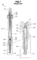
- FIG. 7 shows a conventional-type glow plug 100 that includes a ceramic heater 111 provided with an insulating ceramic substrate 193, a heating element 191 and a pair of electric conductors 195 and 197, a cylindrical metallic shell 113, a metallic sleeve 115, a rod-shaped electrode 117 and a lead wire 199.
- the ceramic heater 111 is fixed in a front end portion 113a of the metallic shell 113 by brazing the metallic sleeve 115 onto the ceramic heater 111 and then brazing the metallic shell 113 onto the metallic sleeve 115.
- the electrode 117 is fixed in a rear portion of the metallic shell 113 by fitting a ring-shaped glass sealant 121 with a bushing 123 and a securing ring 125.
- the heating element 191 is embedded in the ceramic substrate 193, and the electric conductors 195 and 197 connect the heating element 191 to the metallic shell 113 and the electrode 117 via the metallic sleeve 115 and the lead wire 199, respectively.
- a terminal element 119 is fitted on the electrode 117 for connection to an external power source (not shown).
- the electrode 117 is generally made of an iron material with rigidity and has a relatively large diameter (of the order of several millimeters) so as to provide not only excellent electrical properties but also resistance to bending.
- the electrode 117 considerably increases in weight with increase in its length. It is however possible to increase the length of the glow plug 100 by producing both the metallic shell 113 and the electrode 117 in increased lengths, so that the glow plug 100 is suitable for use in a direct-injection engine.
- the electrode 117 is electrically connected to the conductor 197 of the ceramic heater 111 via the lead wire 199, inserted in the metallic shell 113, and then, secured with the glass sealant 121. Because of the above manufacturing process, there is no choice but to fit the glass sealant 121 into a rear end portion of the metallic shell 113.
- the glow plug 100 is reliant only on the glass sealant 121 for securing the electrode 117 in the metallic shell 113, and the electrode 117 is held only at a rear end portion thereof. Accordingly, the strength for securing the electrode 117 in the metallic shell 113 is inevitably low.
- the electrode 117 is susceptible to resonance under engine vibrations and/or thermal shocks caused by engine combustion.
- the electrode 117 may have loosened or ruptured due to the resonance to cause a short or break in the electrode 117.
- the possibility of such a failure increases with increase in the length of the electrode 117.
- the length of the electrode 117 cannot be thus increased as desired.
- the glass sealant 121 needs, after being fitted around the electrode 117 and in the metallic shell 113, to be melted by heat and then solidified to secure the electrode 117 in the metallic shell 113.
- the manufacturing process of the glow plug 100 becomes more complicated due to the heat treatment of the glass sealant 121, which results in high manufacturing cost.
- the glow plug 100 also has to be designed in consideration of the resistance of each plug component to the heat treatment, and the freedom of glow-plug designing becomes unavoidably limited.
- a glow plug comprising: a cylindrical metallic shell; an electrode rod disposed in a rear portion of the metallic shell; a heater disposed in a front portion of the metallic shell, the heater having an insulating substrate, a heating element embedded in the insulating substrate and generating heat upon energization thereof, and electric conductors connecting the heating element to the metallic shell and the electrode rod, respectively; a recess formed in a circumferential surface of the electrode rod; a protrusion formed on an inner surface of the metallic shell and engaged in the recess to secure the electrode rod in the metallic shell; and an electric insulator interposed between the recess and the protrusion to keep the electrode rod insulated from the metallic shell.
- a glow plug comprising: a cylindrical metallic shell; an electrode rod disposed in a rear portion of the metallic shell; a heater disposed in a front portion of the metallic shell, the heater having an insulating substrate, a heating element embedded in the insulating substrate and generating heat upon energization thereof, and electric conductors connecting the heating element to the metallic shell and the electrode rod, respectively; and an electric insulator provided between an inner surface of the metallic shell and a circumferential surface of the electrode rod to keep the electrode rod insulated from the metallic shell, wherein the metallic shell is caulked to the electrode rod at a location axially corresponding to the electric insulator so as to cause deformation in the circumferential surface of the electrode rod and thereby secure the electrode rod in the metallic shell.
- a glow plug comprising: a cylindrical metallic shell; an electrode rod disposed in a rear portion of the metallic shell; a heater disposed in a front portion of the metallic shell, the heater having an insulating substrate, a heating element embedded in the insulating substrate and generating heat upon energization thereof, and electric conductors connecting the heating element to the metallic shell and the electrode rod, respectively; and an electric insulator provided between an inner surface of the metallic shell and a circumferential surface of the electrode rod to keep the electrode rod insulated from the metallic shell, wherein the metallic shell has a portion caulked to the electrode rod at a location axially corresponding to the electric insulator so that the circumferential surface of the electrode rod becomes deformed to define therein a recessed portion engaged with the caulked portion with the electric insulator interposed between the caulked portion and the recessed portion so as to secure the electrode rod in the metallic shell by engagement of the caulked portion and the recessed portion
- FIG. 1 is a sectional view of a glow plug according to a first embodiment of the present invention.
- FIGS. 2A and 2B are schematic illustrations showing how the glow plug is manufactured according to the first embodiment of the present invention.
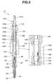
- FIG. 3 is a sectional view of a glow plug according to a second embodiment of the present invention.
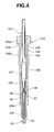
- FIG. 4 is a schematic illustration showing how the glow plug is manufactured according to the second embodiment of the present invention.
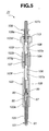
- FIG. 5 is a sectional view of a glow plug according to a third embodiment of the present invention.
- FIG. 6 is a sectional view of a glow plug according to a fourth embodiment of the present invention.
- FIG. 7 is a sectional view of a conventional type glow plug.
- FIGS. 1, 2A and 2B A first embodiment of the present invention will be now explained with reference to FIGS. 1, 2A and 2B.
- a glow plug 1 according to the first embodiment of the invention has a cylindrical metallic shell 103, a ceramic heater 101, a metallic sleeve 105, an electrode rod 107, an electric insulator 106 and a coiled lead wire 99 as shown in FIG. 1.
- the metallic shell 103 is made of e.g. carbon steel (such as S45C, SUM24L, SWCH6 or SUS430) and includes front, middle and rear straight-cylindrical parts 103a, 103b and 103c.
- the diameters of the front, middle and rear straight-cylindrical parts 103a, 103b and 103c are made equal to one another.
- a screw thread 103g for mounting the glow plug 1 on a cylinder head (not shown) is formed on an outer surface of the middle straight-cylindrical part 103b.
- a tool engaging portion 103d for engaging thereon a tool (such as a torque wrench) to mount the glow plug 1 on the cylinder head is formed at a rear end of the metallic shell 103.
- the tool engaging portion 103d is shaped like a hexagonal-head bolt (although not shown in detail in the drawings) in the first embodiment.
- the outer diameter of the tool engaging portion 103d is made larger than the outer diameters of the other portions 103a, 103b and 103c, and the inner diameter of the tool engaging portion 103d is made larger at a rear end thereof to provide a sealant-installation space 103e.
- the ceramic heater 101 is formed into a cylindrical shape and disposed in a front end portion of the metallic shell 103 with a front end of the ceramic heater 101 protruded from the metallic shell 103.
- the ceramic heater 101 has an insulating ceramic substrate 93, a U-shaped heating element 91 embedded in a front portion of the ceramic substrate 93 with two ends thereof facing rearward, and electric conductors 95 and 97 (made of high-melting metal) embedded in a rear portion of the ceramic substrate 93.
- the metallic sleeve 105 is fitted around and brazed to an axially middle portion of the ceramic heater 101, whereas a rear end portion of the metallic sleeve 105 is fitted in and brazed to the front end portion of the metallic shell 103 .
- the electric conductor 95 has a front end electrically connected to one end of the heating element 91 and a rear end exposed at the surface of the ceramic substrate 93 and electrically connected to the metallic shell 103 via the metallic sleeve 105.
- the electric conductor 97 has a front end electrically connected to the other end of the heating element 91 and a rear end exposed at the surface of the ceramic substrate 93 and electrically connected to the electrode rod 107 via the lead wire 99.
- the electrode rod 107 is made of steel (e.g. S45C) that is as soft as or softer than the steel of the metallic shell 103, and has a substantially cylindrical shape throughout its length.
- the electrode rod 107 is coaxially disposed in a rear portion of the metallic shell 103 such that a front end of the electrode rod 107 opposes to a rear end 101a of the ceramic heater 101 with some space left therebetween.
- a rear end 107c of the electrode rod 107 is protruded from the metallic shell 103 for connection to an external power source.
- the protruded end 107c of the electrode rod 107 is occasionally referred to as a "terminal".
- the electrode rod 107 has at the front end thereof a joint portion 107b made in a smaller diameter so that the lead wire 99 is silver-brazed to the joint portion 107b.
- the electric insulator 106 is provided within the metallic shell 103 to circumferentially cover an axially middle portion of the electrode rod 107. In the first embodiment, the electric insulator 106 is situated toward the front on the electrode rod 107.
- the metallic shell 103 is caulked radially inwardly to the electrode rod 107 at a location axially corresponding to the electric insulator 106, thereby causing deformation in a circumferential surface 108 of the electrode rod 7 to define a caulked portion 103f (as a protrusion on an inner surface 104 of the metallic shell 103) and a recessed portion 107a (as a recess in the circumferential surface 108 of the electrode rod 107).
- the caulked portion 103f is made smaller in diameter than the straight-cylindrical parts 103a, 103b and 103c.
- the caulked portion 103f may become smoothly constricted or have a polygonal shape such as a hexagonal shape or an octagonal shape when taken in transverse section (i.e. when viewed in the axial direction of the glow plug 1).
- the recessed portion 107a has a shape to fit with the caulked portion 103f.
- the caulked portion 103f of the metallic shell 103 is engaged in the recessed portion 107a of the electrode rod 107 with the electric insulator 106 interposed between the protruded portion 103f and the recessed portion 107a.
- the electric insulator 106 is axially longer than the caulked portion 103f and the recessed portion 107a, the insulation between the metallic shell 103 and the electrode rod 107 can be established assuredly.
- the electric insulator 106 is preferably in the form of either a tube made of an electrically-insulating flexible (soft) resin fitted around the electrode rod 107 or a coating of an electrically insulating flexible resin applied to the circumferential surface 108 of the electrode rod 107.
- the resin of the electric insulator 106 needs to be selected according to its heat resistance, strength and the like. As there is a case where the glow plug 1 becomes heated to more than 150°C, it is desirable that the resin has a heat resistance of 200°C or higher.
- the resin has a high degree of flexibility such that the electric insulator 106 can be readily deformed without being broken and damaged when the metallic shell 103 is caulked to the electrode rod 107 via the electric insulator 106.
- electrically insulating resin include: general-purpose engineering plastics, such as polyamide, polyethylene terephthalate (PET) and polybutylene terephthalate (PBT); and super engineering plastics, such as polyimide, polyetheretherketone (PEEK) and polyphenylene sulfide (PPS).
- a fluorocarbon resin such as polyvinylidene fluoride
- a fluorocarbon resin such as polyvinylidene fluoride
- a commercially available electrically insulating resin tube such as SUMITUBE K (made of polyvinylidene fluoride) manufactured by Sumitomo Electric Fine Polymer Inc., can be used as the electric insulator 106.
- the electric insulator 106 may be a silicone tube.
- the metallic shell 103 and the electrode rod 107 are made of iron materials, it may be also possible to form the electric insulator 106 into an oxide coating.
- the thickness of the electric insulator 106 is preferably made as small as possible where the electric insulator 106 can provide proper insulation between the metallic shell 103 and the electrode rod 107 even when the electric insulator 106 gets deformed by caulking the metallic shell 103 to the electrode rod 107.
- the thickness of the electric insulator 106 is controlled to 0.01 to 0.5 mm.
- the thickness of the electric insulator 106 exceeds 0.5 mm, it is easier to cause deformation in the electric insulator 106 but difficult to cause deformation in the circumferential surface 108 of the electrode rod 107.
- the thickness of the electric insulator 106 is controlled to 0.15 mm in the first embodiment.
- An insulating bushing (as a sealant) 113 is pushed in the sealant-installation space 103e so as to be located around a rear end portion of the electrode rod 107, and a cylindrical securing member 109 is fitted around and radially inwardly caulked at a portion 109a to the electrode rod 107 so as to hold the bushing 113 down to the sealant-installation section 103e.
- This also makes it possible to secure the electrode rod 107 in the metallic shell 103 while keeping the electrode rod 107 insulated from the metallic shell 103.
- the glow plug 1 is mounted in the cylinder head by means of the screw thread 103g such that the front end portion of the ceramic heater 101 is located in an engine combustion chamber.
- the heating element 101 becomes energized to generate heat so as to aid fuel ignition in the combustion chamber.
- the above-structured glow plug 1 can be manufactured by the following procedure.
- a subassembly is prepared by arranging the electric insulator 106 around the electrode rod 107, connecting the conductor 95 to the electrode rod 107 via the lead wire 99, and then, brazing the metallic sleeve 105 onto the ceramic heater 101, as shown in FIG. 2A.
- the electrically insulating resin tube is prepared with predetermined dimensions (such as thickness, inner diameter and length), fitted around the electrode rod 107, heated to shrink and adhered to the circumferential surface 108 of the electrode rod 107.
- the electric insulator 106 may be formed by pasting an electrically insulating resin film, applying a liquid of electrically insulating resin material or electrostatic painting or spraying an electrically insulating resin powder.
- the subassembly is inserted in the metallic shell 103 and held in position such that the front end portion of the ceramic heater 101 and the terminal 107c of the electrode rod 107 are protruded from the metallic shell 103. Then, the metallic shell 103 is brazed onto the metallic sleeve 105. At this time, both the metallic shell 103 and the electrode rod 107 are substantially cylindrical in shape.
- the metallic shell 103 is caulked radially inwardly to the electrode rod 107 via the electric insulator 106 by means of a pair of dies D.
- the pair of dies D has a shape to form the portions 103f and 107a into e.g. a hexagonal shape.
- the glow plug 1 is completed by fitting the bushing 113 in the sealant-installation space 103e of the metallic shell 103, fitting the fixing member 109 around the terminal 107c of the electrode rod 107, and caulking the fixing member 109 at the portion 109a to hold the bushing 113 down.
- the electrode rod 107 can be tightly secured in the metallic shell 103 by caulking the metallic shell 103 to the electrode rod 107 and thereby engaging the caulked portion 103f in the recessed portion 107a with the electric insulator 106 interposed between the caulked portion 103f and the recessed portion 107a.
- the location where the metallic shell 103 is caulked to the electrode rod 107 via the electric insulator 106 is not particularly limited, and the metallic shell 103 can be caulked to the electrode rod 107 at a location situated toward the front on the electrode rod 107.
- the location and area where the metallic shell 103 is caulked to the electrode rod 107 can be determined according to the length of the electrode rod 107, the required strength for securing the electrode rod 107 in the metallic shell 103, and the like. It is thus possible to improve the strength for securing the electrode rod 107 in the metallic shell 103. Even when the electrode rod 107 is axially subjected to a large external force with the metallic shell 103 fastened to the cylinder head, the electrode rod 107 is able to withstand such an axial external force. In the case where the caulked portion 103f and the recessed portion 107a are polygonal in transverse section, the electrode rod 107 is also able to withstand a radial external force.
- the glow plug 1 can be thus designed with a higher degree of freedom.
- a glow plug 21 of the second embodiment is structurally similar to the glow plug 1 of the first embodiment, except for the configurations of the electric insulator 106 and of the electrode rod 107.
- the electrode rod 107 includes small-diameter parts 128 and a large-diameter part 127 between the small-diameter parts 128.
- the large-diameter part 127 is made larger in diameter than the small-diameter parts 127.
- Each of the large-diameter part 127 and the small-diameter parts 128 has a straight cylindrical shape, and the large- and small-diameter parts 27 and 28 are aligned coaxially.
- the electric insulator 106 is provided to cover the large-diameter parts 127 and slightly extend over the small-diameter parts 128.
- the metallic shell 103 is caulked to the large-diameter part 127 of the electrode rod 107 via the electric insulator 106 so as to form the recessed portion 107a in the large-diameter part 127.
- the glow plug 21 can be manufactured in the same manner as to the glow plug 1.
- the metallic shell 103 can be caulked to the large-diameter part 127 of the electrode rod 107 more easily and assuredly without the risk to short out the electrode rod 107.
- the electric insulator 106 can be made in a smaller thickness.
- a third embodiment of the present invention will be explained with reference to FIG. 5.
- a glow plug 31 of the third embodiment is structurally similar to the glow plug 1 of the first embodiment, except that the metallic shell 103 is caulked to the electrode rod 107 at two locations.
- two electric insulators 106 are provided around the electrode rod 107, and the metallic shell 103 is caulked radially inwardly to the electrode rod 107 at locations axially corresponding to the respective electric insulators 106 to defines two caulked portions 103f and two recessed portion 107a.
- the glow plug 31 can be manufactured in the same manner as to the glow plug 1.
- more than two electric insulators 106 may be provided so that the metallic shell 103 is caulked to the electrode rod 107 at locations axially corresponding to the respective electric insulators 106.
- the area where the metallic shell 103 is caulked to the electrode rod 107 can be determined according to the locations of caulking, the number of the locations of caulking the length of the electrode rod 107, the required strength for securing the electrode rod 107 in the metallic shell 103, and the like.
- the electrode rod 107 may be formed with a plurality of large-diameter parts 127 so that the metallic shell 103 is caulked to the large-diameter parts 127 of the electrode rod 107 via the respective electric insulators 106.
- the electrode rod 107 in the metallic shell 103 more tightly by caulking the metallic shell 103 to the electrode rod 107 at a plurality of locations.
- the glow plug 31 is produced in a small diameter.
- the thickness of the metallic shell 103 is often made smaller although the strength of the metallic shell 103 is lowered. It is however possible to allow the electrode rod 107 to compensate for the strength of the metallic shell 103 by caulking the metallic shell 103 to the electrode rod 107 at a plurality of locations.
- a glow plug 41 of the fourth embodiment is structurally similar to the glow plug 1 of the first embodiment, except that the metallic shell 103 is caulked to the electrode rod 107 at a location between the tool engaging portion 103d and the straight-cylindrical part 103b on which the thread screw 103g is formed.
- the electric insulator 106 is arranged at a rear side of the screw thread 103g.
- the metallic shell 103 is caulked to the electrode rod 107 via the electric insulator 106 to thereby form the caulked portion 103f between the straight-cylindrical part 103b and the tool engaging portion 103d.
- the circumferential surface 108 of the electrode rod 107 becomes deformed to define the recessed portion 107a. That is , both the caulked portion 103f and the recessed portion 107a are located at the rear side of the screw thread 103g.
- the metallic shell 103 may be misaligned at the time of caulking the metallic shell 103 to the electrode rod 107.
- the metallic shell 103 is caulked to the electrode rod 107 so as to cause deformation in the electrode rod 107 and thereby define the caulked portion 103f and the recessed portion 107a.
- the electrode rod 107 may be formed with the recessed portion 107a in advance of assembling the metallic shell 103 and the electrode rod 107, and then, secured in the metallic shell 103 by forming the protruded portion 103f on the metallic shell 103 so as to engage the protruded portion 103f with the recessed portion 107a.
- the electric insulator 106 may be provided to cover the whole of the circumferential surface 108 of the electrode rod 107.
- the electric insulator 106 may be applied to the inner surface 104 of the metallic shell 103 or to both the inner surface 104 of the metallic shell 103 and the circumferential surface 108 of the electrode rod 107.
- the scope of the invention is defined with reference to the following claims.
Landscapes
- Engineering & Computer Science (AREA)
- Chemical & Material Sciences (AREA)
- Combustion & Propulsion (AREA)
- Mechanical Engineering (AREA)
- General Engineering & Computer Science (AREA)
- Resistance Heating (AREA)
Applications Claiming Priority (2)
| Application Number | Priority Date | Filing Date | Title |
|---|---|---|---|
| JP2002234619 | 2002-08-12 | ||
| JP2002234619 | 2002-08-12 |
Publications (3)
| Publication Number | Publication Date |
|---|---|
| EP1391656A2 true EP1391656A2 (fr) | 2004-02-25 |
| EP1391656A3 EP1391656A3 (fr) | 2008-03-05 |
| EP1391656B1 EP1391656B1 (fr) | 2014-04-23 |
Family
ID=31185146
Family Applications (1)
| Application Number | Title | Priority Date | Filing Date |
|---|---|---|---|
| EP03018324.8A Expired - Lifetime EP1391656B1 (fr) | 2002-08-12 | 2003-08-12 | Bougie à incandescence |
Country Status (2)
| Country | Link |
|---|---|
| US (1) | US6900412B2 (fr) |
| EP (1) | EP1391656B1 (fr) |
Cited By (4)
| Publication number | Priority date | Publication date | Assignee | Title |
|---|---|---|---|---|
| EP1936275A3 (fr) * | 2006-12-19 | 2010-04-28 | NGK Spark Plug Co., Ltd. | Bougie de préchauffage et son procédé de fabrication |
| EP2725299A1 (fr) * | 2012-10-26 | 2014-04-30 | SIEVA d.o.o., PE Spodnja Idrija | Bougie de préchauffage comprenant une gaine électriquement isolante et procédé de fabrication de la bougie |
| FR2998949A1 (fr) * | 2012-12-04 | 2014-06-06 | Bosch Gmbh Robert | Bougie de prechauffage de moteur diesel |
| WO2015173017A1 (fr) * | 2014-05-13 | 2015-11-19 | Robert Bosch Gmbh | Electrode de prechauffage a joint d'isolation |
Families Citing this family (12)
| Publication number | Priority date | Publication date | Assignee | Title |
|---|---|---|---|---|
| US7034253B2 (en) * | 2003-04-07 | 2006-04-25 | Ngk Spark Plug Co., Ltd. | Ceramic heater with ring member electrically connecting the heater to lead terminal core rod |
| CN101061352B (zh) * | 2004-10-28 | 2010-10-13 | 圣戈本陶瓷及塑料股份有限公司 | 陶瓷点火器 |
| US20070035249A1 (en) * | 2005-08-10 | 2007-02-15 | Geza Cseh | Lamp with inner capsule |
| US7470875B1 (en) | 2005-12-16 | 2008-12-30 | Locust Usa, Inc. | Ignitor plug |
| JP5102530B2 (ja) * | 2006-05-19 | 2012-12-19 | 日本特殊陶業株式会社 | グロープラグ及びその製造方法 |
| US8022337B2 (en) | 2008-06-10 | 2011-09-20 | Locust, Usa, Inc. | Ignitor plug assembly |
| DE102010013333B4 (de) * | 2010-03-30 | 2012-05-24 | Borgwarner Beru Systems Gmbh | Glühkerze |
| DE102010062443A1 (de) * | 2010-12-06 | 2012-06-06 | Robert Bosch Gmbh | Glühkerze und Verfahren zu deren Herstellung |
| US20160128387A1 (en) * | 2014-08-29 | 2016-05-12 | Shenzhen Smoore Technology Limited | Electronic cigarette and method for manufacturing electronic cigarette |
| KR101706635B1 (ko) * | 2015-07-22 | 2017-02-16 | 주식회사 유라테크 | 글로우 플러그의 단자 조립체 |
| DE102016114929B4 (de) * | 2016-08-11 | 2018-05-09 | Borgwarner Ludwigsburg Gmbh | Druckmessglühkerze |
| CN107104307A (zh) * | 2017-03-23 | 2017-08-29 | 袁芳革 | 一种耐高温的接线端子 |
Family Cites Families (13)
| Publication number | Priority date | Publication date | Assignee | Title |
|---|---|---|---|---|
| DE2835236C2 (de) * | 1978-08-11 | 1986-05-28 | Robert Bosch Gmbh, 7000 Stuttgart | Glühstiftkerze für Brennkraftmaschinen |
| JPS5952726B2 (ja) * | 1981-06-24 | 1984-12-21 | 日本特殊陶業株式会社 | シ−ズ型グロ−プラグの取付金具にグロ−チュ−ブを接合する方法 |
| JPS60103229A (ja) * | 1983-11-10 | 1985-06-07 | Ngk Spark Plug Co Ltd | 自己制御型セラミツクグロ−プラグ |
| JPS6446520A (en) * | 1987-08-12 | 1989-02-21 | Nippon Denso Co | Resistance device for preheating plug of diesel engine |
| US6036829A (en) * | 1997-02-10 | 2000-03-14 | Denso Corporation | Oxygen sensor |
| US5882233A (en) * | 1997-02-26 | 1999-03-16 | Suntec & Co., Ltd. | Pin plug including conductive insert |
| JPH112406A (ja) * | 1997-06-13 | 1999-01-06 | Kyocera Corp | グロープラグ |
| DE10041282B4 (de) * | 2000-08-22 | 2005-02-10 | Beru Ag | Verfahren zur Verbindung eines Heizstabes einer Glühkerze mit ihrem Glühkerzenkörper und eine entsprechende Glühkerze |
| JP4169929B2 (ja) * | 2000-12-22 | 2008-10-22 | 日本特殊陶業株式会社 | グロープラグ |
| US6610964B2 (en) * | 2001-03-08 | 2003-08-26 | Stephen J. Radmacher | Multi-layer ceramic heater |
| US20020166855A1 (en) * | 2001-05-11 | 2002-11-14 | Renwick Ian J. | Electric heater having dielectric sleeve |
| DE60228021D1 (de) * | 2001-05-28 | 2008-09-18 | Ngk Spark Plug Co | Heizung und Glühkerze |
| JP2002359060A (ja) * | 2001-05-31 | 2002-12-13 | Ngk Spark Plug Co Ltd | ヒータ、及びヒータの製造方法 |
-
2003
- 2003-08-11 US US10/637,572 patent/US6900412B2/en not_active Expired - Lifetime
- 2003-08-12 EP EP03018324.8A patent/EP1391656B1/fr not_active Expired - Lifetime
Non-Patent Citations (1)
| Title |
|---|
| None |
Cited By (7)
| Publication number | Priority date | Publication date | Assignee | Title |
|---|---|---|---|---|
| EP1936275A3 (fr) * | 2006-12-19 | 2010-04-28 | NGK Spark Plug Co., Ltd. | Bougie de préchauffage et son procédé de fabrication |
| EP2725299A1 (fr) * | 2012-10-26 | 2014-04-30 | SIEVA d.o.o., PE Spodnja Idrija | Bougie de préchauffage comprenant une gaine électriquement isolante et procédé de fabrication de la bougie |
| FR2998949A1 (fr) * | 2012-12-04 | 2014-06-06 | Bosch Gmbh Robert | Bougie de prechauffage de moteur diesel |
| WO2014086798A1 (fr) * | 2012-12-04 | 2014-06-12 | Robert Bosch Gmbh | Bougie de préchauffage de moteur diesel |
| WO2015173017A1 (fr) * | 2014-05-13 | 2015-11-19 | Robert Bosch Gmbh | Electrode de prechauffage a joint d'isolation |
| FR3021094A1 (fr) * | 2014-05-13 | 2015-11-20 | Bosch Gmbh Robert | Electrode de prechauffage a joint d'isolation |
| CN106461217A (zh) * | 2014-05-13 | 2017-02-22 | 罗伯特·博世有限公司 | 具有绝缘衬垫的预热电极 |
Also Published As
| Publication number | Publication date |
|---|---|
| EP1391656B1 (fr) | 2014-04-23 |
| US20040026399A1 (en) | 2004-02-12 |
| EP1391656A3 (fr) | 2008-03-05 |
| US6900412B2 (en) | 2005-05-31 |
Similar Documents
| Publication | Publication Date | Title |
|---|---|---|
| EP1391656B1 (fr) | Bougie à incandescence | |
| US5852280A (en) | Ceramic heater | |
| US8633640B2 (en) | Spark plug | |
| JPH0339212B2 (fr) | ||
| US6759796B2 (en) | Compact spark plug and method for its production | |
| JP4175970B2 (ja) | グロープラグ | |
| KR100449203B1 (ko) | 세라믹 히터형 글로 플러그 및 그 제조방법 | |
| JP5485843B2 (ja) | グロープラグ及びその製造方法 | |
| US9091443B2 (en) | Glow plug and method for manufacturing glow plug | |
| CN1292196C (zh) | 柴油发动机用热线引火塞及其制造方法 | |
| EP0989370A2 (fr) | Métal pour extrémité de capteur d'incandescence | |
| JP4309757B2 (ja) | セラミックヒーター | |
| US9611827B2 (en) | Internal combustion engine mounted with combustion pressure sensor incorporated glow plug and sensor nonincorporated glow plug | |
| JP3873444B2 (ja) | グロープラグ及びその製造方法 | |
| JP4572492B2 (ja) | セラミックスグロープラグおよびその製造方法 | |
| JP4295164B2 (ja) | グロープラグ | |
| JP6075921B2 (ja) | ディーゼルエンジンの予熱プラグ | |
| JP3834952B2 (ja) | グロープラグの製造方法 | |
| KR101586878B1 (ko) | 글로 플러그 | |
| JP5830369B2 (ja) | グロープラグ | |
| JP2002174423A (ja) | グロープラグ | |
| KR100906357B1 (ko) | 글로우 플러그 | |
| JP6045902B2 (ja) | グロープラグ | |
| JP2002098332A (ja) | グロープラグ | |
| US20020079801A1 (en) | Spark plug having a central electrode which is welded or soldered on and method for its production |
Legal Events
| Date | Code | Title | Description |
|---|---|---|---|
| PUAI | Public reference made under article 153(3) epc to a published international application that has entered the european phase |
Free format text: ORIGINAL CODE: 0009012 |
|
| AK | Designated contracting states |
Kind code of ref document: A2 Designated state(s): AT BE BG CH CY CZ DE DK EE ES FI FR GB GR HU IE IT LI LU MC NL PT RO SE SI SK TR |
|
| AX | Request for extension of the european patent |
Extension state: AL LT LV MK |
|
| PUAL | Search report despatched |
Free format text: ORIGINAL CODE: 0009013 |
|
| AK | Designated contracting states |
Kind code of ref document: A3 Designated state(s): AT BE BG CH CY CZ DE DK EE ES FI FR GB GR HU IE IT LI LU MC NL PT RO SE SI SK TR |
|
| AX | Request for extension of the european patent |
Extension state: AL LT LV MK |
|
| 17P | Request for examination filed |
Effective date: 20080318 |
|
| AKX | Designation fees paid |
Designated state(s): DE FR |
|
| 17Q | First examination report despatched |
Effective date: 20100429 |
|
| GRAP | Despatch of communication of intention to grant a patent |
Free format text: ORIGINAL CODE: EPIDOSNIGR1 |
|
| INTG | Intention to grant announced |
Effective date: 20131126 |
|
| GRAS | Grant fee paid |
Free format text: ORIGINAL CODE: EPIDOSNIGR3 |
|
| GRAA | (expected) grant |
Free format text: ORIGINAL CODE: 0009210 |
|
| AK | Designated contracting states |
Kind code of ref document: B1 Designated state(s): DE FR |
|
| REG | Reference to a national code |
Ref country code: DE Ref legal event code: R096 Ref document number: 60346035 Country of ref document: DE Effective date: 20140528 |
|
| REG | Reference to a national code |
Ref country code: DE Ref legal event code: R097 Ref document number: 60346035 Country of ref document: DE |
|
| PLBE | No opposition filed within time limit |
Free format text: ORIGINAL CODE: 0009261 |
|
| STAA | Information on the status of an ep patent application or granted ep patent |
Free format text: STATUS: NO OPPOSITION FILED WITHIN TIME LIMIT |
|
| 26N | No opposition filed |
Effective date: 20150126 |
|
| REG | Reference to a national code |
Ref country code: DE Ref legal event code: R097 Ref document number: 60346035 Country of ref document: DE Effective date: 20150126 |
|
| REG | Reference to a national code |
Ref country code: FR Ref legal event code: PLFP Year of fee payment: 14 |
|
| REG | Reference to a national code |
Ref country code: FR Ref legal event code: PLFP Year of fee payment: 15 |
|
| REG | Reference to a national code |
Ref country code: FR Ref legal event code: PLFP Year of fee payment: 16 |
|
| PGFP | Annual fee paid to national office [announced via postgrant information from national office to epo] |
Ref country code: DE Payment date: 20190730 Year of fee payment: 17 Ref country code: FR Payment date: 20190711 Year of fee payment: 17 |
|
| REG | Reference to a national code |
Ref country code: DE Ref legal event code: R119 Ref document number: 60346035 Country of ref document: DE |
|
| PG25 | Lapsed in a contracting state [announced via postgrant information from national office to epo] |
Ref country code: DE Free format text: LAPSE BECAUSE OF NON-PAYMENT OF DUE FEES Effective date: 20210302 Ref country code: FR Free format text: LAPSE BECAUSE OF NON-PAYMENT OF DUE FEES Effective date: 20200831 |