EP1391675A1 - Echangeur thermique multitubulaire - Google Patents
Echangeur thermique multitubulaire Download PDFInfo
- Publication number
- EP1391675A1 EP1391675A1 EP02726453A EP02726453A EP1391675A1 EP 1391675 A1 EP1391675 A1 EP 1391675A1 EP 02726453 A EP02726453 A EP 02726453A EP 02726453 A EP02726453 A EP 02726453A EP 1391675 A1 EP1391675 A1 EP 1391675A1
- Authority
- EP
- European Patent Office
- Prior art keywords
- tube
- heat transmitting
- heat
- heat exchanger
- fluid
- Prior art date
- Legal status (The legal status is an assumption and is not a legal conclusion. Google has not performed a legal analysis and makes no representation as to the accuracy of the status listed.)
- Granted
Links
- 239000012530 fluid Substances 0.000 claims abstract description 44
- 239000003344 environmental pollutant Substances 0.000 abstract description 8
- 231100000719 pollutant Toxicity 0.000 abstract description 8
- 238000012546 transfer Methods 0.000 description 16
- 238000001816 cooling Methods 0.000 description 9
- 239000000463 material Substances 0.000 description 8
- 238000005476 soldering Methods 0.000 description 8
- 239000000498 cooling water Substances 0.000 description 7
- 238000004519 manufacturing process Methods 0.000 description 6
- 238000004088 simulation Methods 0.000 description 6
- 238000003466 welding Methods 0.000 description 6
- 230000008878 coupling Effects 0.000 description 5
- 238000010168 coupling process Methods 0.000 description 5
- 238000005859 coupling reaction Methods 0.000 description 5
- 238000010586 diagram Methods 0.000 description 5
- 230000003247 decreasing effect Effects 0.000 description 4
- 229910000679 solder Inorganic materials 0.000 description 4
- 239000004071 soot Substances 0.000 description 3
- PXHVJJICTQNCMI-UHFFFAOYSA-N Nickel Chemical compound [Ni] PXHVJJICTQNCMI-UHFFFAOYSA-N 0.000 description 2
- 230000015572 biosynthetic process Effects 0.000 description 2
- 239000007788 liquid Substances 0.000 description 2
- 238000003825 pressing Methods 0.000 description 2
- 238000012545 processing Methods 0.000 description 2
- RYGMFSIKBFXOCR-UHFFFAOYSA-N Copper Chemical compound [Cu] RYGMFSIKBFXOCR-UHFFFAOYSA-N 0.000 description 1
- 239000000853 adhesive Substances 0.000 description 1
- 230000000903 blocking effect Effects 0.000 description 1
- 238000002485 combustion reaction Methods 0.000 description 1
- 238000011109 contamination Methods 0.000 description 1
- 229910052802 copper Inorganic materials 0.000 description 1
- 239000010949 copper Substances 0.000 description 1
- 238000013016 damping Methods 0.000 description 1
- 230000006866 deterioration Effects 0.000 description 1
- 238000011161 development Methods 0.000 description 1
- 230000000694 effects Effects 0.000 description 1
- 238000010438 heat treatment Methods 0.000 description 1
- 238000003780 insertion Methods 0.000 description 1
- 230000037431 insertion Effects 0.000 description 1
- 238000000034 method Methods 0.000 description 1
- 229910052759 nickel Inorganic materials 0.000 description 1
- 230000003647 oxidation Effects 0.000 description 1
- 238000007254 oxidation reaction Methods 0.000 description 1
- 238000005192 partition Methods 0.000 description 1
- 230000002093 peripheral effect Effects 0.000 description 1
Images



Classifications
-
- F—MECHANICAL ENGINEERING; LIGHTING; HEATING; WEAPONS; BLASTING
- F28—HEAT EXCHANGE IN GENERAL
- F28F—DETAILS OF HEAT-EXCHANGE AND HEAT-TRANSFER APPARATUS, OF GENERAL APPLICATION
- F28F3/00—Plate-like or laminated elements; Assemblies of plate-like or laminated elements
- F28F3/02—Elements or assemblies thereof with means for increasing heat-transfer area, e.g. with fins, with recesses, with corrugations
- F28F3/04—Elements or assemblies thereof with means for increasing heat-transfer area, e.g. with fins, with recesses, with corrugations the means being integral with the element
- F28F3/042—Elements or assemblies thereof with means for increasing heat-transfer area, e.g. with fins, with recesses, with corrugations the means being integral with the element in the form of local deformations of the element
- F28F3/044—Elements or assemblies thereof with means for increasing heat-transfer area, e.g. with fins, with recesses, with corrugations the means being integral with the element in the form of local deformations of the element the deformations being pontual, e.g. dimples
-
- F—MECHANICAL ENGINEERING; LIGHTING; HEATING; WEAPONS; BLASTING
- F28—HEAT EXCHANGE IN GENERAL
- F28D—HEAT-EXCHANGE APPARATUS, NOT PROVIDED FOR IN ANOTHER SUBCLASS, IN WHICH THE HEAT-EXCHANGE MEDIA DO NOT COME INTO DIRECT CONTACT
- F28D7/00—Heat-exchange apparatus having stationary tubular conduit assemblies for both heat-exchange media, the media being in contact with different sides of a conduit wall
- F28D7/16—Heat-exchange apparatus having stationary tubular conduit assemblies for both heat-exchange media, the media being in contact with different sides of a conduit wall the conduits being arranged in parallel spaced relation
- F28D7/1684—Heat-exchange apparatus having stationary tubular conduit assemblies for both heat-exchange media, the media being in contact with different sides of a conduit wall the conduits being arranged in parallel spaced relation the conduits having a non-circular cross-section
-
- F—MECHANICAL ENGINEERING; LIGHTING; HEATING; WEAPONS; BLASTING
- F28—HEAT EXCHANGE IN GENERAL
- F28F—DETAILS OF HEAT-EXCHANGE AND HEAT-TRANSFER APPARATUS, OF GENERAL APPLICATION
- F28F1/00—Tubular elements; Assemblies of tubular elements
- F28F1/02—Tubular elements of cross-section which is non-circular
-
- F—MECHANICAL ENGINEERING; LIGHTING; HEATING; WEAPONS; BLASTING
- F28—HEAT EXCHANGE IN GENERAL
- F28F—DETAILS OF HEAT-EXCHANGE AND HEAT-TRANSFER APPARATUS, OF GENERAL APPLICATION
- F28F1/00—Tubular elements; Assemblies of tubular elements
- F28F1/10—Tubular elements and assemblies thereof with means for increasing heat-transfer area, e.g. with fins, with projections, with recesses
- F28F1/40—Tubular elements and assemblies thereof with means for increasing heat-transfer area, e.g. with fins, with projections, with recesses the means being only inside the tubular element
-
- F—MECHANICAL ENGINEERING; LIGHTING; HEATING; WEAPONS; BLASTING
- F28—HEAT EXCHANGE IN GENERAL
- F28F—DETAILS OF HEAT-EXCHANGE AND HEAT-TRANSFER APPARATUS, OF GENERAL APPLICATION
- F28F3/00—Plate-like or laminated elements; Assemblies of plate-like or laminated elements
- F28F3/02—Elements or assemblies thereof with means for increasing heat-transfer area, e.g. with fins, with recesses, with corrugations
-
- F—MECHANICAL ENGINEERING; LIGHTING; HEATING; WEAPONS; BLASTING
- F28—HEAT EXCHANGE IN GENERAL
- F28D—HEAT-EXCHANGE APPARATUS, NOT PROVIDED FOR IN ANOTHER SUBCLASS, IN WHICH THE HEAT-EXCHANGE MEDIA DO NOT COME INTO DIRECT CONTACT
- F28D21/00—Heat-exchange apparatus not covered by any of the groups F28D1/00 - F28D20/00
- F28D21/0001—Recuperative heat exchangers
- F28D21/0003—Recuperative heat exchangers the heat being recuperated from exhaust gases
Definitions
- the present invention relates to a multi-tube heat exchanger in which both ends of each of multiple heat transmitting tubes, comprised of inner tubes (heat transmitting tubes) which a first fluid passes and an outer tube (body) which a second fluid passes, are held and disposed on introduction side/discharge side holding plates located on first fluid introduction side and first fluid discharge side each.
- the present invention concerns a heat exchanger which executes heat exchange by feeding high-speed high-temperature gas (gas) through the heat transmitting tubes while feeding cooling water (liquid) through the body (outer tube).
- the present invention is preferably applied to an emission gas cooling apparatus (which requires a high degree of heat exchanging performance) and the like, which cools emission gas of an internal combustion engine with cooling water.
- a multi-tube heat exchanger 12 shown in FIGs. 1, 2 are often used if a high degree of heat exchanging performance is required like the case described above.
- multiple inner tubes (heat transmitting tubes) group 14 which the first fluid (high-temperature gas) passes through and an outer tube (body) 16 which the second fluid (cooling water) passes through are provided.
- Both ends of each of the multiple heat transmitting tubes (heat transmitting tubes) 14, 14, ⁇ are held and disposed on introduction side/discharge side holding plates 18, 20 located on the first fluid introduction side and first fluid discharge side.
- the multiple heat transmitting tubes 14, 14 ⁇ are disposed within the body 16 via introduction side/discharge side holding plates (tube sheet) 18, 20 located on both sides of the body 16.
- the both ends of the body 16 have introduction/discharge ports (connection pipes) 26, 28 with flanges 26a, 28a via conical introduction side/discharge side rectifying cylinders (rectifying portions) 22, 24 of truncated cone shape, so that the first fluid (high-temperature gas) can pass through the heat transmitting tubes 14, 14 ...
- the body 16 has introduction/discharge nozzles 30, 32 on its top and bottom faces for the second fluid (cooling water) to be capable of passing outside each heat transmitting tube 14.
- the above-mentioned multi-tube heat exchanger 12 needs a number of production steps and its weight tends to be increased.
- the inventors of the present invention have proposed a multi-tube heat exchanger having a structure described below (Japanese Patent Application No. 2000-061541: Japanese Patent Application No. 2001-24890; being not published on the priority date) in order to provide a multi-tube heat exchanger capable of increasing heat exchanging efficiency easily and additionally decreasing the number of manufacturing steps.
- Multi-tube heat exchanger containing multiple heat transmitting tubes disposed inside the body characterized in that each of the respective heat transmitting tubes is comprised of a heat transmitting tube main body having a flat section and a number of heat transmitting fins connecting between opposing faces in the length direction of the heat transmitting tube main bodies.
- the present invention intends to provide amulti-tube heat exchanger capable of increasing heat exchanging performance without increasing its heat transmitting area and solving a problem on drop in heat exchanging efficiency due to adhering pollutant or the like.
- a multi-tube heat exchanger comprising an inner tube (heat transmitting tube) group in which a first fluid passes and an outer tube (body) in which a second fluid passes, both ends of each multiple heat transmitting tubes being held and disposed on introduction/discharge side holding plates located on each of first fluid introduction side and first fluid discharge side, wherein the heat transmitting tube is constituted of only a heat transmitting tube main body while longitudinal eddy generating means is disposed in the heat transmitting tube main body.
- the longitudinal eddy generating means is disposed in the heat transmitting tube main body, when the first fluid (high-speed gas or the like) passes through the heat transmitting tube main body which is a high-speed gas flow path, eddies (longitudinal eddies) are generated. The first fluid is disturbed by this eddy thereby relatively increasing heat transmitting rate (heat exchanging efficiency).
- heat exchanging efficiency cooling efficiency
- the heat exchanging efficiency can be increased even if the heat transmitting fins for increasing the heat transmitting area is not incorporated in the heat transmitting tube main body unlike the conventional example.
- the projection group which is the longitudinal eddy generating means does not increase the heat exchanging efficiency due to increase of the heat transmitting area
- the degree of drop in heat transmitting efficiency accompanied by pollutant adhering to the heat transmitting wall face is small and further, adhering of pollutant to the heat transmitting wall face due to generation of the longitudinal eddies is relatively decreased and therefore naturally, partial clogging due to pollutant never occurs.
- the degree of drop in heat exchanging efficiency with a passage of time is lower than the conventional heat transmitting fin incorporated type. That is, the problem about drop in heat exchanging efficiency accompanied by pollutant adhering to the heat transmitting wall face is solved.
- a longitudinal eddy generating means is provided by forming a number of sheet-like or lump-like projections (projection group) at a predetermined interval (predetermined pitch) in the length direction and width direction on one or both of opposing wall faces on longer sides of the heat transmitting tube main body.
- the aforementioned projections are formed directly on a wall face of the heat transmitting tube main body by press treatment (stamping etc.).
- the projection is so formed that a face opposing a flow thereof is substantially rectangular and further, by adopting one of following requirements or combining: (1) an attack angle thereof is 20°-80°, (2) the height and width thereof are 0.1-0.8 times the height and width of a flow path thereof, (3) the pitch thereof in flow direction is 1-5 times the height or width of the flow path thereof, press treatment is facilitated, the longitudinal eddy becomes likely to be generated and the heat exchanging efficiency is increased.
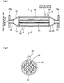
- FIGS. 3, 4, 5, 6 show an example of the multi-tube heat exchanger 112 according to this embodiment.
- multiple heat transmitting tubes 114 are disposed via tube fixing plates 118, 120 in a square rod body 116 having the introduction side/discharge side holding plates (tube sheets) 118, 120 on both ends.
- First fluid introduction port /discharge port (connecting pipes) 126, 128 having flanges 126a, 128a are provided on both ends of the square rod body 116 via introduction side/discharge side rectifying cylinders (rectifying portions) 122, 124, so that a first fluid (high-temperature gas) can pass through heat transmitting tubes 114, 114, ...
- the heat transmitting tube 114 is composed of only a heat transmitting tube main body 134 constituted of substantially a flat tube.
- Introduction/discharge side nozzles 130, 132 are provided on the top and bottom of the square rod body 116 and a second fluid (cooling water) is allowed to pass outside the heat transmitting tubes 114.
- the body may be formed in a cylindrical body 116A as shown in FIG. 5 (corresponding to a portion taken along the line 4(5)-4(5) in FIG. 3), the square rod formation enables the quantity of components to be reduced more as described above. That is, if it is formed in a cylindrical form, it is necessary to prepare components 114, 114', 114" each having a different width as a heat transmitting tube as indicated in the same Figure.
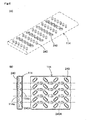
- each main body (flat tube) of these heat transmitting tubes 114, 114', 114" contains a flow generating means. More specifically, one or both of opposing wall faces 114a, 114b on longer sides of the flat tube (heat transmitting tube main body) have a number of plate-like or lump-like projections (projection groups) (lump-like projections in the same Figure) 240. As for the configuration of the projection 240, its face opposing flow is substantially rectangular while its plan view shape is substantially rectangular (elongated circle in the same Figure). If the projection 240 adopts this configuration, preferably, it can be formed easily by pressing such as stamping.
- the projection 240 is formed such that it is projected toward a longitudinal center axis C of each of the bodies 116, 116A in this Figure, it may be formed so as to be directed outwardly (toward the periphery).
- projections 240 are formed obliquely on one wall face 114a of a flat tube alternately in a high-speed gas flow direction, it is permissible to dispose obliquely arranged projections 240 on one wall face 114a of the flat tube like FIG. 6(A) and dispose parallel projections 240Abetween the obliquely arrangedpro jections 240 in the length direction on the other wall face 114b in parallel to the gas flow direction.
- This parallel projection 240A blocks an interference of longitudinal eddies generated by adjacent obliquely arranged projections and reduces pressure loss and further an action for blocking clogging of soot can be expected.
- the shape of the face opposing a flow and its plan view shape of the projection 240 are not substantially restricted to the rectangular shape, however may be selected arbitrarily from semi-circle, circle, trapezoid, triangle and the like.
- projection projection group
- metallic thin plates 0.3 - 0.5 mmt
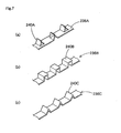
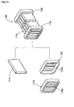
- 236A, 236B, 236C having projection plates 240A, square projections 240B or mountain-like projections 240C formed at a predetermined pitch on a belt-like or rectangular plate (belt-like plate in the same Figure) by soldering or the like to the flat tube 114.
- the multi-tube heat exchanger is produced.
- this heat exchanger has a smaller heat transmitting area than the conventional heat exchanger having the heat transmitting fins, a same or higher heat exchanging efficiency can be secured due to generation of eddies. Further, because the heat transmitting area is small, a sudden drop of the heat exchanging efficiency due to generation of contamination (soot, oil stain and the like) on the heat transmitting part (including the heat transmitting fins) hardly occurs.
- the section of the heat transmitting tube main body is flat, it may be round in section as shown in FIG. 2, or triangular, square or the like in section.
- These heat transmitting tubes are produced in succession by transfer press from a single metallic pipe or by pressing or roll forming from a single sheet material (hoop material).
- the lateral section of the outer shape of the heat transmitting tube may be, as shown in the same Figure, of square pipe or round pipe like the conventional example, instead of being flat.
- the square pipe is more preferable because it allows a belt-like plate having more projections (projection group) to be inserted and fixed more easily upon formation of the projections which will be described below.
- a thin belt-like plate having the projecting plates or projecting lumps are fixed at predetermined pitch within a pipe like a case of the above-described heat transmitting fin.
- FIGs. 8, 9 show models of various forming embodiment of the projection 140.
- FIGs. 8, 9 show models in which the gas flow path is formed in a rectangular section (square) and sheet-like projections 140 are disposed at a predetermined distance for convenience of explanation.
- the face opposing a flow of the projection 140 is rectangular as described previously, it may be selected arbitrarily from trapezoid, triangle 140B (FIG. 9(a)), semi-circle and the like in terms of plan view shape. Further, it is permissible to dispose 140A, 140A as pair in the form of an arrow (counter) as shown in FIG. 9(b). That is, any shape is permissible as long as it generates eddies in flow of high-temperature gas or the like (generating gas disturbance) so as to contribute to improvement of heat transmitting rate (heat exchanging efficiency).
- the respective configuration characteristic factors are, in FIG. 8, (a) ⁇ : projection attack angle and p: projection pitch, (b) ⁇ : projecting plate tilt angle and h: projecting plate height, (c) h: projecting plate height and H: flow path height.
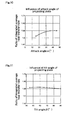
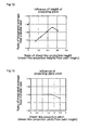
- Integrated average heat transfer rate (on an entire peripheral wall face) is obtained through simulation by changing the respective configuration characteristics with the tilt angle: 90°, attack angle: 45°, flow path shape: 4 mm x 4 mm x 220 mmL, projection shape: 1.5 mm x 1.5 mm x 0.5 mmt as reference.
- a ratio of the heat transfer rate (ordinate axis) in each graph is expressed with heat transfer rate in case where no projection plate exists under the above condition being 1.0.
- FIGs. 10-13 indicating a simulation result presents following facts.
- the inventors of the present invention carried out the same simulation experiment upon a flow path in which the projecting plates are formed and respective flow paths based on a configuration of FIG. 9(a)(in which the shape of the projecting plate is changed to an inscribed triangle shape from the above-mentioned basic shape) and a configuration of FIG. 9(b). Consequently, the configuration of FIG. 9(a) improved the heat transfer rate by about 35% as compared to a case where there was no projection and the configuration of FIG. 9(b) improved the heat transfer rate by about 53% as compared to a case where there was no projection, thereby obviously indicating that the heat transfer rate (heat exchanging rate: high-temperature gas cooling efficiency) was improved when the projecting plates were formed.
- a flat tube (section of short cut section in this Figure) 134 which turns to a heat transmitting tube main body, and introduction side/discharge side holding plates (tube sheets) 118, 120 are prepared.
- the section of the flat tube may be rectangular or elongated circle.
- a number of lump-like projections are formed at a predetermined distance (predetermined pitch) in the length direction on one or both of opposing wall faces on longer sides of the flat tube 134 by press treatment such as stamping.
- each of the flat tube (heat transmitting tube main body) 134 and the introduction/discharge side holding plate differs depending upon used material and endurance period, for example, that of the former should be 0.1-1.0 mm (preferably 0.3-0.8 mm) and that of the latter should be 0.5-3 mm (preferably 1-2 mm) in case of stainless.
- the heat transmitting tube unit 138 is prepared.
- the coupling style at this time shall be usually soldering (soldering).
- solder material for use at this time for example, if the material of the heat exchanger is of stainless, usually, copper solder or nickel solder shall be used. Heating/cooling condition upon soldering is set up considering the kind and heat capacity of the solder material.
- the introduction side/discharge side holding plates 118, 120 of the heat transmitting tube unit 138 After the outer periphery of the introduction side/discharge side holding plates 118, 120 of the heat transmitting tube unit 138 is coated with soldering material, it is inserted partly into the square rod body 116 and then the large-diameter side of the pyramid frustum cylinder which constitutes the rectifying portion 118.
- the introduction port/discharge port (connecting pipe) 126, 128 integrated with the flanges 126a, 128a are inserted into the smaller diameter side and coupled (finally fixed) with each other.
- this coupling final fixing means, TIG welding or laser welding, which produces little oxidation deterioration and secures coupling strength easily, is preferable, other arc welding, resistance welding or coupling with heat resistant adhesive agent is acceptable.
- the body (outer tube) 116 may be divided to halves and coupled together later.
- the body 116 is integrated by resistance welding in a separate process.
- the number of manufacturing steps is increased, a problem about metallic crack due to differences in soldering heat efficiency and cooling velocity between the front surface and inner surface after the soldering unlikely occurs.
- the heat exchanger which executes heat exchange by passing high-speed, high-temperature gas (gas) through the straight heat transmitting tube (inner tube) while cooling water (liquid) through the body (outer tube), a combination of the first fluid and the second fluid may be determined arbitrarily as long as there is a difference in temperature which allows heat exchange.
- emission gas of automobile to be passed through the heat exchanger has a gas velocity of 0-50 m/s and a gas temperature of 120-700°C.
- selection of the first fluid (which passes through the inner tube) and the second fluid (which passes through the outer tube) is carried out based on the standard described below (see pp.365-366, "KAGAKU KOGAKU JITEN” edited by KAGAKU KOGAKU KYOKAI, published by MARUSEN, May 30, 1974).
- Fluid to be passed through the outer tube (out of the tube) fluid whose flow rate is small, fluid whose viscosity is high, fluid whose tolerable pressure loss is small
- the present invention can also be applied to an example in which the heat transmitting tubes are bent halfway and an example in which the heat transmitting tubes are bent in U shape so that both ends thereof are located on the same side.
- the present invention can be applied to a heat exchanger in which the rectifying portion (rectifying chamber) is provided on only an end and the introduction-in/-out ports are located on the same side while that end portion is partitioned with a partition plate.
Landscapes
- Engineering & Computer Science (AREA)
- Physics & Mathematics (AREA)
- Thermal Sciences (AREA)
- Mechanical Engineering (AREA)
- General Engineering & Computer Science (AREA)
- Geometry (AREA)
- Heat-Exchange Devices With Radiators And Conduit Assemblies (AREA)
Applications Claiming Priority (3)
| Application Number | Priority Date | Filing Date | Title |
|---|---|---|---|
| JP2001156703A JP3774843B2 (ja) | 2001-05-25 | 2001-05-25 | 多管式熱交換器 |
| JP2001156703 | 2001-05-25 | ||
| PCT/JP2002/004924 WO2002097352A1 (fr) | 2001-05-25 | 2002-05-22 | Echangeur thermique multitubulaire |
Publications (3)
| Publication Number | Publication Date |
|---|---|
| EP1391675A1 true EP1391675A1 (fr) | 2004-02-25 |
| EP1391675A4 EP1391675A4 (fr) | 2006-04-12 |
| EP1391675B1 EP1391675B1 (fr) | 2009-11-18 |
Family
ID=19000677
Family Applications (1)
| Application Number | Title | Priority Date | Filing Date |
|---|---|---|---|
| EP02726453A Revoked EP1391675B1 (fr) | 2001-05-25 | 2002-05-22 | Echangeur thermique multitubulaire |
Country Status (5)
| Country | Link |
|---|---|
| US (1) | US7055586B2 (fr) |
| EP (1) | EP1391675B1 (fr) |
| JP (1) | JP3774843B2 (fr) |
| DE (1) | DE60234441D1 (fr) |
| WO (1) | WO2002097352A1 (fr) |
Cited By (9)
| Publication number | Priority date | Publication date | Assignee | Title |
|---|---|---|---|---|
| WO2007005479A1 (fr) * | 2005-06-30 | 2007-01-11 | Honeywell International Inc. | Echangeur de chaleur avec surfaces de tuyau chanfreinees |
| WO2007027318A1 (fr) * | 2005-08-30 | 2007-03-08 | Caterpillar Inc. | Tube conçu pour un refroidisseur d’air |
| WO2007042529A1 (fr) * | 2005-10-13 | 2007-04-19 | Basf Se | Echangeur de chaleur tubulaire, et procede pour supprimer les matieres dissoutes dans une solution polymere, par degazage dans un echangeur de chaleur tubulaire |
| US7311137B2 (en) | 2002-06-10 | 2007-12-25 | Wolverine Tube, Inc. | Heat transfer tube including enhanced heat transfer surfaces |
| US7637012B2 (en) | 2002-06-10 | 2009-12-29 | Wolverine Tube, Inc. | Method of forming protrusions on the inner surface of a tube |
| US8573022B2 (en) | 2002-06-10 | 2013-11-05 | Wieland-Werke Ag | Method for making enhanced heat transfer surfaces |
| EP2770290A4 (fr) * | 2011-10-18 | 2015-05-27 | Calsonic Kansei Corp | Échangeur de chaleur de gaz d'échappement |
| DE102019106012A1 (de) * | 2019-03-08 | 2020-09-10 | Mahle International Gmbh | Wärmetauscheranordnung und Wärmetauscher |
| EP3417228B1 (fr) * | 2016-02-19 | 2022-12-21 | Valeo Termico S.A. | Canal pour la circulation d'un fluide dans un échangeur de chaleur, et échangeur de chaleur |
Families Citing this family (43)
| Publication number | Priority date | Publication date | Assignee | Title |
|---|---|---|---|---|
| AU2002368421B2 (en) * | 2002-12-02 | 2007-10-04 | Lg Electronics Inc. | Heat exchanger of ventilating system |
| CN1211633C (zh) * | 2003-05-10 | 2005-07-20 | 清华大学 | 不连续双斜内肋强化换热管 |
| KR100991206B1 (ko) | 2003-09-06 | 2010-11-05 | 한라공조주식회사 | 고압 냉매 사이클용 열교환기 및 그에 대한 제조 방법 |
| EP2267393B1 (fr) * | 2003-10-28 | 2017-06-28 | MAHLE Behr GmbH & Co. KG | Canal d'écoulement pour un échangeur de chaleur |
| JP4614266B2 (ja) * | 2004-07-23 | 2011-01-19 | 臼井国際産業株式会社 | 流体攪拌用フィン並びに該フィンを内装した伝熱管および熱交換器または熱交換型ガス冷却装置 |
| JP4654021B2 (ja) | 2004-12-22 | 2011-03-16 | 本田技研工業株式会社 | 多管式熱交換装置及びその製造方法 |
| JP2006284165A (ja) * | 2005-03-07 | 2006-10-19 | Denso Corp | 排気ガス熱交換器 |
| DE102005021464A1 (de) * | 2005-05-10 | 2006-11-16 | Modine Manufacturing Co., Racine | Vorrichtung zur Zwischenkühlung |
| KR101250771B1 (ko) * | 2006-09-21 | 2013-04-04 | 한라공조주식회사 | 열교환기 |
| DE102007040793A1 (de) * | 2007-08-28 | 2009-03-05 | Behr Gmbh & Co. Kg | Wärmetauscher |
| US8757250B2 (en) * | 2007-09-14 | 2014-06-24 | Advantest Corporation | Advanced thermal control interface |
| TW200940198A (en) * | 2008-03-27 | 2009-10-01 | Rachata Leelaprachakul | Processes for textured pipe manufacturer |
| JP4485583B2 (ja) * | 2008-07-24 | 2010-06-23 | トヨタ自動車株式会社 | 熱交換器及びその製造方法 |
| CN102292611A (zh) * | 2009-01-22 | 2011-12-21 | 大金工业株式会社 | 热交换器及具备该热交换器的热泵式热水供给机 |
| US9562722B2 (en) * | 2009-03-13 | 2017-02-07 | Carrier Corporation | Manifold assembly for distributing a fluid to a heat exchanger |
| JP5477466B2 (ja) * | 2010-05-17 | 2014-04-23 | トヨタ自動車株式会社 | Egrガス冷却構造を有するシリンダヘッドおよびその製造方法 |
| KR20130088758A (ko) * | 2010-06-28 | 2013-08-08 | 히로시 미치와키 | 변주통상체 |
| CN101900497A (zh) * | 2010-07-12 | 2010-12-01 | 广东万家乐燃气具有限公司 | 大气式燃烧的燃气热水器或燃气两用炉用不锈钢主换热器 |
| CN101943529A (zh) * | 2010-09-29 | 2011-01-12 | 西安航天华威化工生物工程有限公司 | 高温气体干法降温装置及方法 |
| JP2012083026A (ja) * | 2010-10-12 | 2012-04-26 | Isuzu Motors Ltd | 熱交換器 |
| PL2630414T3 (pl) * | 2010-10-20 | 2016-09-30 | Zespół sterowania przepływem | |
| JP2012137251A (ja) | 2010-12-27 | 2012-07-19 | Maruyasu Industries Co Ltd | 多管式熱交換器 |
| JP5589860B2 (ja) * | 2011-01-17 | 2014-09-17 | 株式会社デンソー | 熱交換器 |
| JP5887115B2 (ja) * | 2011-11-30 | 2016-03-16 | 東京ラヂエーター製造株式会社 | インナーフィン |
| JP5915187B2 (ja) * | 2012-01-10 | 2016-05-11 | マツダ株式会社 | 熱交換器 |
| DE102012013755B8 (de) * | 2012-07-12 | 2022-01-13 | Al-Ko Therm Gmbh | Wärmetauscherplatteneinheit, Wärmetauscher und Verfahren zur Herstellung eines Wärmetauschers |
| US20180106558A9 (en) * | 2013-06-27 | 2018-04-19 | Dana Canada Corporation | Fluid channels having performance enhancement features and devices incorporating same |
| US10156157B2 (en) * | 2015-02-13 | 2018-12-18 | United Technologies Corporation | S-shaped trip strips in internally cooled components |
| ITUB20155713A1 (it) * | 2015-11-18 | 2017-05-18 | Robur Spa | Tubo di fiamma migliorato. |
| JP2017101904A (ja) * | 2015-12-04 | 2017-06-08 | 三桜工業株式会社 | 熱交換器用フィン |
| CA2964399C (fr) * | 2016-04-12 | 2025-08-26 | 6353908 Canada Inc. | Conduit d'echangeur thermique et echangeur thermique |
| EP3270085B1 (fr) * | 2016-07-12 | 2019-11-06 | Borgwarner Emissions Systems Spain, S.L.U. | Échangeur thermique pour système egr |
| US10352278B2 (en) * | 2016-08-19 | 2019-07-16 | Ge Global Sourcing Llc | Method and systems for an exhaust gas recirculation cooler including two sections |
| DE102017222742A1 (de) * | 2017-12-14 | 2019-06-19 | Hanon Systems | Rohr, insbesondere Flachrohr für einen Abgaskühler und Abgaskühler |
| DE102017223616A1 (de) * | 2017-12-21 | 2019-06-27 | Mahle International Gmbh | Flachrohr für einen Abgaskühler |
| JP7159806B2 (ja) * | 2018-11-21 | 2022-10-25 | トヨタ自動車株式会社 | 熱交換器 |
| DE102019204640A1 (de) | 2019-04-02 | 2020-10-08 | Mahle International Gmbh | Wärmeübertrager |
| CN110926256B (zh) * | 2019-11-06 | 2022-03-08 | 华为数字能源技术有限公司 | 换热板以及包含该换热板的换热器 |
| US11280559B2 (en) * | 2020-05-12 | 2022-03-22 | Hanon Systems | Dumbbell shaped plate fin |
| US11639828B2 (en) * | 2020-06-25 | 2023-05-02 | Turbine Aeronautics IP Pty Ltd | Heat exchanger |
| FR3129716B1 (fr) * | 2021-11-30 | 2023-12-22 | Valeo Systemes Thermiques | Eléments de perturbation avancés pour l’amélioration de la performance des tubes |
| JP7738496B2 (ja) * | 2022-02-04 | 2025-09-12 | 三菱重工業株式会社 | 熱交換器 |
| JP7748930B2 (ja) * | 2022-11-30 | 2025-10-03 | 三菱重工業株式会社 | 熱交換器 |
Family Cites Families (26)
| Publication number | Priority date | Publication date | Assignee | Title |
|---|---|---|---|---|
| US2526157A (en) * | 1941-08-07 | 1950-10-17 | Ramen Torsten | Apparatus for heat exchange between liquids |
| US2988335A (en) * | 1958-03-06 | 1961-06-13 | Gen Motors Corp | Heat exchangers |
| DE1601236A1 (de) * | 1967-10-31 | 1970-05-21 | Piccardo Dr Ing Mario | Waermeaustauscher |
| CH516130A (de) * | 1970-03-02 | 1971-11-30 | Foerderung Forschung Gmbh | Parallelstrom-Röhrenwärmeaustauscher |
| US4470452A (en) * | 1982-05-19 | 1984-09-11 | Ford Motor Company | Turbulator radiator tube and radiator construction derived therefrom |
| JPS6317393A (ja) * | 1986-07-08 | 1988-01-25 | Nippon Denso Co Ltd | 熱交換器 |
| US4836276A (en) * | 1987-03-09 | 1989-06-06 | Nippondenso Co., Ltd. | Heat exchanger for engine oil |
| JPH01184399A (ja) * | 1988-01-18 | 1989-07-24 | Nippon Denso Co Ltd | 熱交換器用チューブ |
| JP3224141B2 (ja) | 1992-02-25 | 2001-10-29 | 本多電子株式会社 | 超音波モータ |
| DE9406197U1 (de) * | 1994-04-14 | 1994-06-16 | Behr Gmbh & Co | Wärmetauscher zum Kühlen von Abgas eines Kraftfahrzeugmotors |
| DE19526917A1 (de) * | 1995-07-22 | 1997-01-23 | Fiebig Martin Prof Dr Ing | Längswirbelerzeugende Rauhigkeitselemente |
| DE19540683A1 (de) | 1995-11-01 | 1997-05-07 | Behr Gmbh & Co | Wärmeüberträger zum Kühlen von Abgas |
| DE19654363B4 (de) | 1996-12-24 | 2007-09-27 | Behr Gmbh & Co. Kg | Abgaswärmeübertrager für einen Verbrennungsmotor |
| DE19654366B4 (de) * | 1996-12-24 | 2005-10-20 | Behr Gmbh & Co Kg | Strömungskanal, insbesondere für einen Abgaswärmeübertrager |
| DE19654368B4 (de) * | 1996-12-24 | 2006-01-05 | Behr Gmbh & Co. Kg | Wärmeübertrager, insbesondere Abgaswärmeübertrager |
| DE19654367A1 (de) * | 1996-12-24 | 1998-06-25 | Behr Gmbh & Co | Verfahren zum Anbringen von Laschen und/oder Vorsprüngen an einem Feinblech und Feinblech mit Laschen und/oder Vorrichtungen sowie Rechteckrohr aus Feinblechen |
| JP3957021B2 (ja) | 1998-05-22 | 2007-08-08 | カルソニックカンセイ株式会社 | 熱交換器 |
| DE19833338A1 (de) | 1998-07-24 | 2000-01-27 | Modine Mfg Co | Wärmetauscher, insbesondere Abgaswärmetauscher |
| SE517450C2 (sv) * | 1999-06-18 | 2002-06-04 | Valeo Engine Cooling Ab | Fluidtransportrör samt sätt och anordning för framställning av detsamma |
| US6247523B1 (en) * | 1999-07-30 | 2001-06-19 | Denso Corporation | Exhaust gas heat exchanger |
| JP2001041109A (ja) | 1999-07-30 | 2001-02-13 | Denso Corp | 排気熱交換器 |
| JP2001041676A (ja) | 1999-08-02 | 2001-02-16 | Hitachi Ltd | プレート式熱交換器 |
| JP2001241872A (ja) * | 1999-12-24 | 2001-09-07 | Maruyasu Industries Co Ltd | 多管式熱交換器 |
| DE19963373A1 (de) * | 1999-12-28 | 2001-07-12 | Abb Alstom Power Ch Ag | Vorrichtung zur Kühlung einer, einen Strömungskanal umgebenden Strömungskanalwand mit wenigstens einem Rippenzug |
| DE10127084B4 (de) * | 2000-06-17 | 2019-05-29 | Mahle International Gmbh | Wärmeübertrager, insbesondere für Kraftfahrzeuge |
| EP2738112B1 (fr) * | 2011-07-26 | 2017-03-01 | Toyo Seikan Group Holdings, Ltd. | Récipient antigoutte |
-
2001
- 2001-05-25 JP JP2001156703A patent/JP3774843B2/ja not_active Expired - Fee Related
-
2002
- 2002-05-22 WO PCT/JP2002/004924 patent/WO2002097352A1/fr not_active Ceased
- 2002-05-22 US US10/473,599 patent/US7055586B2/en not_active Expired - Lifetime
- 2002-05-22 EP EP02726453A patent/EP1391675B1/fr not_active Revoked
- 2002-05-22 DE DE60234441T patent/DE60234441D1/de not_active Expired - Lifetime
Cited By (11)
| Publication number | Priority date | Publication date | Assignee | Title |
|---|---|---|---|---|
| US7311137B2 (en) | 2002-06-10 | 2007-12-25 | Wolverine Tube, Inc. | Heat transfer tube including enhanced heat transfer surfaces |
| US7637012B2 (en) | 2002-06-10 | 2009-12-29 | Wolverine Tube, Inc. | Method of forming protrusions on the inner surface of a tube |
| US8302307B2 (en) | 2002-06-10 | 2012-11-06 | Wolverine Tube, Inc. | Method of forming protrusions on the inner surface of a tube |
| US8573022B2 (en) | 2002-06-10 | 2013-11-05 | Wieland-Werke Ag | Method for making enhanced heat transfer surfaces |
| WO2007005479A1 (fr) * | 2005-06-30 | 2007-01-11 | Honeywell International Inc. | Echangeur de chaleur avec surfaces de tuyau chanfreinees |
| WO2007027318A1 (fr) * | 2005-08-30 | 2007-03-08 | Caterpillar Inc. | Tube conçu pour un refroidisseur d’air |
| WO2007042529A1 (fr) * | 2005-10-13 | 2007-04-19 | Basf Se | Echangeur de chaleur tubulaire, et procede pour supprimer les matieres dissoutes dans une solution polymere, par degazage dans un echangeur de chaleur tubulaire |
| EP2770290A4 (fr) * | 2011-10-18 | 2015-05-27 | Calsonic Kansei Corp | Échangeur de chaleur de gaz d'échappement |
| US9103250B2 (en) | 2011-10-18 | 2015-08-11 | Calsonic Kansei Corporation | Exhaust gas heat exchanger |
| EP3417228B1 (fr) * | 2016-02-19 | 2022-12-21 | Valeo Termico S.A. | Canal pour la circulation d'un fluide dans un échangeur de chaleur, et échangeur de chaleur |
| DE102019106012A1 (de) * | 2019-03-08 | 2020-09-10 | Mahle International Gmbh | Wärmetauscheranordnung und Wärmetauscher |
Also Published As
| Publication number | Publication date |
|---|---|
| EP1391675A4 (fr) | 2006-04-12 |
| US7055586B2 (en) | 2006-06-06 |
| JP2002350081A (ja) | 2002-12-04 |
| WO2002097352A1 (fr) | 2002-12-05 |
| JP3774843B2 (ja) | 2006-05-17 |
| EP1391675B1 (fr) | 2009-11-18 |
| US20040134640A1 (en) | 2004-07-15 |
| DE60234441D1 (de) | 2009-12-31 |
Similar Documents
| Publication | Publication Date | Title |
|---|---|---|
| EP1391675B1 (fr) | Echangeur thermique multitubulaire | |
| EP1714100B1 (fr) | Méthode de production d'un échangeur thermique à ailettes en plaques brasées | |
| CN100437010C (zh) | 热交换器用扁平管 | |
| US20200370834A1 (en) | Enhanced heat transfer surface | |
| CN100458347C (zh) | 相互连接的微通道管 | |
| WO2010090557A1 (fr) | Échangeur thermique à plaques | |
| EP2577207A2 (fr) | Echangeur de chaleur tubulaire multipasse et plaque de separation entre passes, couvercle de conduits et procedes associes | |
| KR101967273B1 (ko) | 쉘 앤드 튜브 타입 열교환기 | |
| CA2961065C (fr) | Echangeur de chaleur modulable par l'utilisateur et son procede d'utilisation | |
| CA2419009C (fr) | Echangeur de chaleur ameliore avec encrassement reduit | |
| JP2003294382A (ja) | 熱交換器 | |
| US5067562A (en) | Heat exchanger having fins which are different from one another in fin thickness | |
| US20130075071A1 (en) | Heat Exchanger | |
| EP1067350A2 (fr) | Plaque avec bossages pour échangeur de chaleur et sa méthode de fabrication | |
| US20090159247A1 (en) | Tube assemblies and combo-coolers incorporating the same | |
| CN107110610A (zh) | 热交换器,特别用于机动车辆的热交换器,以及制造这种热交换器的方法 | |
| EP0632246A2 (fr) | Echageur de chaleur | |
| JP2005049007A (ja) | フィン部材を内装した伝熱管 | |
| JP2002350071A (ja) | 二重管式熱交換器 | |
| JP2001248980A (ja) | 多管式熱交換器 | |
| US20090223656A1 (en) | Heat exchanger tube | |
| JP2010032128A (ja) | 熱交換器用チューブ | |
| JP2005042941A (ja) | 伝熱管並びにこの伝熱管を組み付けた熱交換器 | |
| CN101017041A (zh) | 管束带式换热器 | |
| US20070227713A1 (en) | Heat exchanger tube with a compressed return bend, a serpentine heat exchanger tube with compressed return bends and heat exchanger implementing the same |
Legal Events
| Date | Code | Title | Description |
|---|---|---|---|
| PUAI | Public reference made under article 153(3) epc to a published international application that has entered the european phase |
Free format text: ORIGINAL CODE: 0009012 |
|
| 17P | Request for examination filed |
Effective date: 20031203 |
|
| AK | Designated contracting states |
Kind code of ref document: A1 Designated state(s): AT BE CH CY DE DK ES FI FR GB GR IE IT LI LU MC NL PT SE TR |
|
| A4 | Supplementary search report drawn up and despatched |
Effective date: 20060228 |
|
| 17Q | First examination report despatched |
Effective date: 20081202 |
|
| GRAP | Despatch of communication of intention to grant a patent |
Free format text: ORIGINAL CODE: EPIDOSNIGR1 |
|
| RIN1 | Information on inventor provided before grant (corrected) |
Inventor name: SAKAKIBARA, YASUFUMI,MARUYASU INDUSTRIES CO., LTD Inventor name: HARADA, NARUKI,MARUYASU INDUSTRIES CO., LTD. |
|
| GRAS | Grant fee paid |
Free format text: ORIGINAL CODE: EPIDOSNIGR3 |
|
| GRAA | (expected) grant |
Free format text: ORIGINAL CODE: 0009210 |
|
| RIN1 | Information on inventor provided before grant (corrected) |
Inventor name: HARADA, NARUKI,C/O MARUYASU INDUSTRIES CO., LTD. Inventor name: SAKAKIBARA, YASUFUMI,C/O MARUYASU INDUSTRIES CO., |
|
| AK | Designated contracting states |
Kind code of ref document: B1 Designated state(s): DE FR GB |
|
| REG | Reference to a national code |
Ref country code: GB Ref legal event code: FG4D |
|
| REF | Corresponds to: |
Ref document number: 60234441 Country of ref document: DE Date of ref document: 20091231 Kind code of ref document: P |
|
| PLBI | Opposition filed |
Free format text: ORIGINAL CODE: 0009260 |
|
| PLAX | Notice of opposition and request to file observation + time limit sent |
Free format text: ORIGINAL CODE: EPIDOSNOBS2 |
|
| 26 | Opposition filed |
Opponent name: BEHR GMBH & CO. KG Effective date: 20100817 |
|
| PLAF | Information modified related to communication of a notice of opposition and request to file observations + time limit |
Free format text: ORIGINAL CODE: EPIDOSCOBS2 |
|
| PLBB | Reply of patent proprietor to notice(s) of opposition received |
Free format text: ORIGINAL CODE: EPIDOSNOBS3 |
|
| PLAB | Opposition data, opponent's data or that of the opponent's representative modified |
Free format text: ORIGINAL CODE: 0009299OPPO |
|
| R26 | Opposition filed (corrected) |
Opponent name: BEHR GMBH & CO. KG Effective date: 20100817 |
|
| REG | Reference to a national code |
Ref country code: FR Ref legal event code: PLFP Year of fee payment: 14 |
|
| PLAB | Opposition data, opponent's data or that of the opponent's representative modified |
Free format text: ORIGINAL CODE: 0009299OPPO |
|
| R26 | Opposition filed (corrected) |
Opponent name: MAHLE BEHR GMBH & CO. KG Effective date: 20100817 |
|
| PGFP | Annual fee paid to national office [announced via postgrant information from national office to epo] |
Ref country code: GB Payment date: 20150528 Year of fee payment: 14 |
|
| PGFP | Annual fee paid to national office [announced via postgrant information from national office to epo] |
Ref country code: FR Payment date: 20150518 Year of fee payment: 14 |
|
| PGFP | Annual fee paid to national office [announced via postgrant information from national office to epo] |
Ref country code: DE Payment date: 20150629 Year of fee payment: 14 |
|
| REG | Reference to a national code |
Ref country code: DE Ref legal event code: R064 Ref document number: 60234441 Country of ref document: DE Ref country code: DE Ref legal event code: R103 Ref document number: 60234441 Country of ref document: DE |
|
| RDAF | Communication despatched that patent is revoked |
Free format text: ORIGINAL CODE: EPIDOSNREV1 |
|
| RDAG | Patent revoked |
Free format text: ORIGINAL CODE: 0009271 |
|
| STAA | Information on the status of an ep patent application or granted ep patent |
Free format text: STATUS: PATENT REVOKED |
|
| 27W | Patent revoked |
Effective date: 20151117 |
|
| GBPR | Gb: patent revoked under art. 102 of the ep convention designating the uk as contracting state |
Effective date: 20151117 |