EP1391909A2 - Magnétron - Google Patents
Magnétron Download PDFInfo
- Publication number
- EP1391909A2 EP1391909A2 EP03254254A EP03254254A EP1391909A2 EP 1391909 A2 EP1391909 A2 EP 1391909A2 EP 03254254 A EP03254254 A EP 03254254A EP 03254254 A EP03254254 A EP 03254254A EP 1391909 A2 EP1391909 A2 EP 1391909A2
- Authority
- EP
- European Patent Office
- Prior art keywords
- harmonic
- choke
- magnetron
- cylindrical
- anode
- Prior art date
- Legal status (The legal status is an assumption and is not a legal conclusion. Google has not performed a legal analysis and makes no representation as to the accuracy of the status listed.)
- Granted
Links
Images


Classifications
-
- H—ELECTRICITY
- H01—ELECTRIC ELEMENTS
- H01J—ELECTRIC DISCHARGE TUBES OR DISCHARGE LAMPS
- H01J23/00—Details of transit-time tubes of the types covered by group H01J25/00
- H01J23/36—Coupling devices having distributed capacitance and inductance, structurally associated with the tube, for introducing or removing wave energy
- H01J23/54—Filtering devices preventing unwanted frequencies or modes to be coupled to, or out of, the interaction circuit; Prevention of high frequency leakage in the environment
-
- H—ELECTRICITY
- H01—ELECTRIC ELEMENTS
- H01J—ELECTRIC DISCHARGE TUBES OR DISCHARGE LAMPS
- H01J23/00—Details of transit-time tubes of the types covered by group H01J25/00
- H01J23/14—Leading-in arrangements; Seals therefor
- H01J23/15—Means for preventing wave energy leakage structurally associated with tube leading-in arrangements, e.g. filters, chokes, attenuating devices
-
- H—ELECTRICITY
- H01—ELECTRIC ELEMENTS
- H01J—ELECTRIC DISCHARGE TUBES OR DISCHARGE LAMPS
- H01J25/00—Transit-time tubes, e.g. klystrons, travelling-wave tubes, magnetrons
- H01J25/50—Magnetrons, i.e. tubes with a magnet system producing an H-field crossing the E-field
- H01J25/52—Magnetrons, i.e. tubes with a magnet system producing an H-field crossing the E-field with an electron space having a shape that does not prevent any electron from moving completely around the cathode or guide electrode
- H01J25/58—Magnetrons, i.e. tubes with a magnet system producing an H-field crossing the E-field with an electron space having a shape that does not prevent any electron from moving completely around the cathode or guide electrode having a number of resonators; having a composite resonator, e.g. a helix
- H01J25/587—Multi-cavity magnetrons
Definitions
- the present invention relates to a magnetron for use in microwave ovens and the like, and more particularly to a mechanism for restraining the leakage of harmonic components from the output portion of the magnetron.
- a magnetron for a microwave oven generates a microwave of 2.45 GHz as a fundamental wave.
- the magnetron When generating the microwave, the magnetron generates harmonic components having frequencies of integral multiples of the fundamental wave in addition to the fundamental wave, simultaneously.
- the harmonic components When the harmonic components are radiated from the output portion, just like the fundamental wave, the harmonics are propagated into the microwave oven. Since the wavelengths of the harmonics are short, when they are propagated once into the microwave oven, it is difficult to prevent their leakage to the outside of the microwave oven. Since leakage power leaked to the outside of the microwave oven may cause wireless communication failures, the limit of the leakage is controlled by law in Japan.
- a magnetron provided with a quarter-wave choke at its output portion for outputting a microwave is generally used.
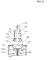
- FIG. 10 is a sectional view showing the main portion of the conventional magnetron.
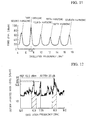
- FIG. 11 is a graph showing the noise levels of respective harmonics in a microwave oven in which the conventional magnetron is used.
- FIG. 12 is a graph showing an example wherein the noise levels in the frequency bands in the vicinity of a third harmonic leaked from the microwave oven in which the conventional magnetron is used is plotted in narrow ranges.
- the vertical axis represents noise level [dBpW]
- the horizontal axis represents oscillation frequency [GHz].
- a plurality of anode segments 102 are secured to the inner wall of an anode cylinder 101, and these anode segments 102 are disposed so as to be directed toward the central axis of the anode cylinder 101.
- a cathode 105 is disposed along the central axis thereof, and each of the upper and lower ends of the cathode 105 is secured to an end hat 106.
- the upper and lower ends of the respective anode segments 102 are connected alternately via a pair of large and small strap rings 103 and 104, respectively.
- metal cylinders 108 are hermetically sealed via magnetic pole pieces 107.
- a cylindrical choke 109 for restraining the third harmonic and a cylindrical choke 110 for restraining the fifth harmonic are disposed substantially coaxially.
- one end of an antenna lead 113 is secured to one of the anode segments 102.
- This antenna lead 113 passes through the magnetic pole piece 107 and extends upward inside the metal cylinder 108 along the central axis thereof.
- the antenna lead 113 passes through the insides of the metal cylinder 108 and passes through an output portion 120 comprising a ceramic cylinder 111 and an exhaust pipe 112 so as not to make contact with the inner face thereof.
- the end of the antenna lead 113 is crimped and secured to the output portion 120 together with the exhaust pipe 112.
- the level of noise leaking from the microwave oven was measured. As shown in FIG. 11, among the noise levels of the respective harmonics of the fundamental wave (2.45 GHz), the level of the third harmonic, a 7.35 GHz band, was higher than the levels of the other harmonics.
- FIG. 12 is a graph showing a result wherein the noise level of the third harmonic leaked from the microwave oven in which the conventional magnetron is used is plotted in narrow ranges.
- the noise level was about 80 dBpW at the third harmonic of 7.35 GHz, about 87 dBpW at the low side band of 6.9 ⁇ 0.15 GHz and about 95 dBpW at the high side band of 8.3 ⁇ 0.15 GHz.
- the conventional magnetron had a choke structure to restrain the third and fifth harmonics.
- the restraint of the noise level of the third harmonic was still insufficient in comparison with the other harmonics as shown in the noise level graphs of FIGS. 11 and 12; in particular, in the low side band of 6.9 ⁇ 0.15 GHz and the high side band of 8.3 ⁇ 0.15 GHz in the frequency bands in the vicinity of the third harmonic, the magnetron had a problem of not producing the effect of the harmonic restraint chokes.
- the present invention is intended to provide a magnetron capable of addressing the problem of the conventional magnetron and capable of securely lowering the noise levels of the third harmonic and the side bands of the third harmonic by using a simple configuration without increasing the number of components.
- a magnetron in accordance with the present invention comprises:
- a magnetron in accordance with another aspect of the present invention comprises:
- a magnetron in accordance with still another aspect of the present invention comprises:
- the third harmonic restraint cylindrical choke may be configured so that the dimension of the inside diameter of the small diameter portion thereof is not more than 1/4 of the wavelength ( ⁇ ) of the third harmonic.
- the third harmonic restraint cylindrical choke may be formed so that the step portion between the small diameter portion and the large diameter portion thereof is substantially Light-angled.
- the third harmonic restraint cylindrical choke may be formed so that the step portion between the small diameter portion and the large diameter portion thereof is inclined.
- the output portion thereof may be installed on the metal cylinder via a cylindrical insulator and may have an exhaust pipe connected to and held on the cylindrical insulator and a cylindrical portion extended in the direction in parallel with the lead-out direction of the antenna lead inside the exhaust pipe, and the cylindrical portion and the antenna lead may constitute a quarter-wave choke for the low side band of the third harmonic.
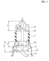
- FIG. 1 is a sectional view showing the main portion of a magnetron in accordance with a first embodiment of the present invention.
- FIG. 2 is a magnified sectional view showing the dimensions of the main portion of the magnetron in accordance with the first embodiment.
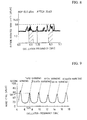
- FIG. 3 is a graph showing the relationship between the length of an antenna lead from the end of an anode segment to a third harmonic restraint choke and noise level.
- FIG. 4 is a graph showing, in detail, the noise levels in the frequency bands in the vicinity of the third harmonic in a microwave oven in which the magnetron in accordance with the first embodiment is used,
- a plurality of plate-formed anode segments 2 are secured to the inner wall of a cylindrical anode cylinder 1, and the anode segments 2 are disposed at equal intervals toward the central axis of the anode cylinder 1.
- a cathode 5 is disposed along the central axis thereof in the vertical direction, and each of the upper and lower ends of the cathode 5 is secured to an end hat 6.
- the lower end of the cathode 5 is not shown.
- the upper and lower ends of the respective anode segments 2 are connected alternately and electrically via a pair of large and small strap rings 3 and 4, respectively.
- metal cylinders 8 are hermetically sealed via magnetic pole pieces 7.
- a third harmonic restraint cylindrical choke 15 for restraining the third harmonic and a fifth harmonic restraint cylindrical choke 10 for restraining the fifth harmonic are disposed substantially coaxially.
- one end (the lower end) of an antenna lead 17 is secured to one of the anode segments 2, and the antenna lead 17 passes through the magnetic pole piece 7 and is led out upward inside the metal cylinder 8 along the central axis thereof.
- the antenna lead 17 passes through the inside of the metal cylinder 8 and passes through an output portion 20 comprising a ceramic cylinder 11 and an exhaust pipe 16 so as not to make contact with the inner face of the side wall thereof.
- the end of the antenna lead 13 is crimped and secured to the output portion 20 together with the exhaust pipe 16.
- the magnetron in accordance with the first embodiment has a structure wherein microwave energy is delivered from the anode segments 2 via the antenna lead 17.
- the antenna lead 17 of the magnetron in accordance with the first embodiment is configured so that the electrical length L1 from the end of the anode segment 2 to the end of the third harmonic restraint choke 15 is 1/2 of the wavelength ( ⁇ ) of the third harmonic. This electrical length L1 is shown in FIG. 1.
- the inventors of the present invention confirmed by experiment that the third harmonic component and the side band components of the third harmonic were restrained significantly.
- the inventors carried out an experiment on the magnetron in accordance with the first embodiment and analyzed the experiment; the details thereof will be described below.
- the metal cylinder 8 and the third harmonic restraint choke 15 disposed therein constitute a quarter-wave choke for the third harmonic and the high side band thereof. Furthermore, the third harmonic restraint choke 15 and the fifth harmonic restraint choke 10 disposed therein constitute a quarter-wave choke for the fifth harmonic and the high side band thereof.
- the inside diameter (J) of the third harmonic restraint choke 15 is about 12 mm
- the groove depth (E) of this third harmonic restraint choke 15 is 10.2 mm
- the groove width (I) thereof in the radial direction is about 2.8 mm.
- the inside diameter (H) of the fifth harmonic restraint choke 10 is about 9 mm
- the groove depth (F) thereof is about 5.3 mm
- the groove width (G) thereof in the radial direction is about 1.5 mm.
- the fifth harmonic restraint choke 10 the third harmonic restraint choke 15 and the quarter-wave chokes comprising the respective corresponding chokes operate independently for the respective harmonics, carries out the maximum restraining actions on the respective harmonics, thereby producing an excellent restraint effect.
- a cylindrical portion 18 extended toward the cathode in the direction in parallel with the downward lead-out direction of the antenna lead 17
- This cylindrical portion 18 and the antenna lead 17 constitute a quarter-wave choke for the low side band of the third harmonic.
- the specific dimensions of the quarter-wave choke for the low side band of the third harmonic are as described below; the groove depth (A) is about 10.2 mm, and the groove width (C) in the radial direction is about 1.9 mm.
- the inside diameter (D) of the cylindrical portion 18 is 6.0 mm
- the distance (B) between the inner face of the exhaust pipe 16 and the outer face of the cylindrical portion 18 is 2.9 mm.
- the groove depth (A), the groove width (C) in the radial direction, the inside diameter (D) of the cylindrical portion 18 and the distance (B) between the inner face of the exhaust pipe 16 and the outer face of the cylindrical portion 18, described above produce an effect of restraining the third harmonic; in particular, the groove depth (A) and the groove width (C) in the radial direction contribute to the restraint of the low side band of the third harmonic.
- the inventors carried out an experiment on the comparison of the outside radiated noise level of the third harmonic depending on the length.
- the result of the experiment is shown in the graph of FIG. 3.
- the horizontal axis represents the length L1 [mm] of the antenna lead 17, and the vertical axis represents the outside radiated noise level [dBpW].
- the third harmonic was able to be restrained to the lowest when the length L1 of the antenna lead 17 from the end of one of the anode segments 2 to which the antenna lead 17 is connected to the end of the third harmonic restraint choke 15 was about 20. 4 mm.
- the inventors carried out an experiment on the comparison with respect to the radiation level of the third harmonic.
- the microwave oven provided with the magnetron under measurement was set inside an anechoic chamber, a water load was disposed inside this microwave oven, a horn antenna and a measuring instrument for measuring the levels of the respective frequency components of a signal from the horn antenna were connected 3 meters away from the microwave oven, and outside radiated noise levels were measured. The result of this measurement is shown in FIG. 4.
- FIG. 4 The result of this measurement is shown in FIG. 4.
- FIG. 4 is a graph showing the outside radiated noise levels measured and plotted in narrow ranges in the frequency bands in the vicinity of the third harmonic from the microwave oven in which the magnetron in accordance with the first embodiment is used.
- the horizontal axis represents oscillation frequency [GHz]
- the vertical axis represents the outside radiated noise level [dBpW] of the third harmonic.
- the noise level was 80 dBpW in the vicinity of 7.35 GHz, triple of the fundamental wave (2.45 GHz); 95 dBpW in the vicinity of 8.3 GHz, the high side band; and 87 dBpW in the vicinity of 6.9 GHz, the low side band.
- the microwave oven in which the magnetron in accordance with the first embodiment of the present invention by setting the electrical length L1 of the antenna lead 17 from the end of the anode segment 2 to the end of the third harmonic restraint choke 15 at 1/2 of the wavelength ( ⁇ ) of the third harmonic, the noise level in the vicinity of 7.35 GHz, the third harmonic, was lowered to 45 dBpW; the noise level in the vicinity of 8.3 GHz, the high side band of the third harmonic, was lowered to 63 dBpW by the cylindrical portion of the metal cylinder 8 and the third harmonic restraint choke 15; and the noise level in the vicinity of the low side band of the third harmonic was lowered to 52 dBpW by the exhaust pipe 16 and the antenna lead 17, as shown in FIG. 4.
- the magnetron in accordance with the first embodiment of the present invention can securely restrain the third harmonic without making the configuration of the output portion thereof complicated or larger, whereby it is possible to obtain a magnetron capable of producing an excellent effect practically.
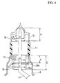
- FIG. 5 is a sectional view showing the main portion of the magnetron in accordance with the second embodiment of the present invention.
- FIG. 6 is a magnified sectional view showing the dimensions of the main portion of the magnetron in accordance with the second embodiment.
- FIG. 7 is a graph showing the relationship between the diameter of the small diameter portion of a third harmonic restraint choke and frequency bands in which restraint is carried out.
- FIG. 8 is a graph showing the noise levels in the frequency bands in the vicinity of the third harmonic in a microwave oven in which the magnetron in accordance with the second embodiment is used.
- a third harmonic restraint choke 19 has a large diameter portion 19b on the output portion side (the upper side) and has a small diameter portion 19a on the cathode side (the lower side), thereby being formed into a cylindrical shape having a step.
- the magnetron in accordance with the second embodiment its configuration is the same as the configuration of the above-mentioned first embodiment except for the third harmonic restraint choke 19 having the small diameter portion 19a and the large diameter portion 19b.
- the magnetron in accordance with the second embodiment is configured so that the electrical length L2 of the antenna lead 17 from the end of the anode segment 2 to which the antenna lead 17 is secured to the end of the third harmonic restraint choke 19 is 1/2 of the wavelength ( ⁇ ) of the third harmonic. This electrical length L2 is shown in FIG. 5.
- the inventors confirmed by experiment that the third harmonic component and the side band components of the third harmonic were restrained significantly.
- the inventors carried out an experiment on the magnetron in accordance with the second embodiment and analyzed the experiment; the details thereof will be described below.
- the metal cylinder 8 and the third harmonic restraint choke 19 disposed therein constitute a quarter-wave choke for the third harmonic and the high side band thereof. Furthermore, the third harmonic restraint choke 19 and the fifth harmonic restraint choke 10 disposed therein constitute a quarter-wave choke for the fifth harmonic and the high side band thereof.
- FIG. 7 is a graph obtained by measuring restrained harmonic components while fixing the dimension of the large diameter portion 19b of the third harmonic restraint choke 19 and changing the diameter of the small diameter portion 19a.
- the inside diameter (H) of the fifth harmonic restraint choke 10 of the magnetron used in the experiment shown in FIG. 7 is about 9 mm, the groove depth (E) thereof is about 5.3 mm, and the groove width (G) thereof in the radial direction is about 1.5 mm.
- the inside diameter (J) of the large diameter portion 19b thereof is about 12 mm, and the groove depth (D) of this third harmonic restraint choke is 10.2 mm.
- the large diameter portion 19b of the third harmonic restraint choke 19 was formed so as to have the above-mentioned dimensions, and comparison was carried out with respect to the outside radiated noise level of the third harmonic in the magnetron while variously changing the diameter of the small diameter portion 19a. The result is shown in the graph of FIG. 7.
- the harmonic components are restrained in a frequency band of about 300 [MHz] as shown in the graph of FIG. 7.
- the inside diameter of the small diameter portion 19a of the third harmonic restraint choke 19 is set at about 9 mm (by setting the groove width (F) in the radial direction at about 4.8 mm), it was confirmed that the level of the third harmonic component can be restrained in a wide frequency band of 0.3 GHz or more.
- the inventors used the magnetron in accordance with the second embodiment of the present invention configured as described above and the conventional magnetron as magnetrons for microwave ovens provided with oven functions and operating on a fundamental wave oscillation frequency of 2.45 GHz and an output power of about 1000 W, and carried out an experiment on the comparison with respect to the radiation level of the third harmonic.
- the measurement method therefor is the same as that for the magnetron in accordance with the above-mentioned first embodiment; that is, the microwave oven provided with the magnetron under measurement was set inside an anechoic chamber, a water load was disposed inside this microwave oven, a horn antenna and a measuring instrument for measuring the levels of the respective frequency components of a signal from the horn antenna were connected 3 meters away from the microwave oven, and outside radiated noise levels were measured.
- FIG. 8 is a graph showing the outside radiated noise levels measured and plotted in narrow ranges in the frequency bands in the vicinity of the third harmonic from the microwave oven in which the magnetron in accordance with the second embodiment is used.
- the horizontal axis represents oscillation frequency [GHz]
- the vertical axis represents the outside radiated noise level [dBpW] of the third harmonic.
- the noise level was 80 dBpW in the vicinity of 7.35 GHz, triple of the fundamental wave (2.45 GHz); 95 dBpW in the vicinity of 8.3 GHz, the high side band; and 87 dBpW in the vicinity of 6.9 GHz, the low side band.
- the third harmonic restraint choke 19 of the magnetron in accordance with the second embodiment of the present invention forms a shape having the large diameter portion 19b and the small diameter portion 19a, the noise level of the high side band (about 8.3 GHz) of the third harmonic is lowered as shown in the graph of FIG. 8 in comparison with the magnetron in accordance with the first embodiment shown in FIG. 4.
- the magnetron in accordance with the second embodiment can restrain the noise level in a wider frequency band.
- FIG. 9 is a graph showing the noise levels of respective harmonics in the microwave oven in which the magnetron in accordance with the second embodiment is used. As shown in FIG. 9, by using the magnetron in accordance with the second embodiment, it can be confirmed that the noise level of the third harmonic is lowered to about 58 dBpW without affecting the noise restraining effect for harmonics other than the third harmonic.
- the magnetron in accordance with the second embodiment of the present invention can securely restrain the third harmonic without making the configuration of the output portion thereof complicated or larger, whereby it is possible to obtain a magnetron capable of producing an excellent effect practically.
- the step portion in the shape having the large diameter portion 19b and the small diameter portion 19a of the third harmonic restraint choke 19 has a nearly right-angled step shape as shown in FIG. 5; however, the present invention is not limited to this kind of shape; the shape may be a tapered shape.
- the magnetron in accordance with the present invention produces an excellent effect of capable of securely restraining the third harmonic and the side bands of the third harmonic as well as the fifth harmonic by using a simple and rational configuration without increasing the number of components.
Landscapes
- Microwave Tubes (AREA)
- Constitution Of High-Frequency Heating (AREA)
Applications Claiming Priority (2)
| Application Number | Priority Date | Filing Date | Title |
|---|---|---|---|
| JP2002222781A JP3622742B2 (ja) | 2002-07-31 | 2002-07-31 | マグネトロン |
| JP2002222781 | 2002-07-31 |
Publications (3)
| Publication Number | Publication Date |
|---|---|
| EP1391909A2 true EP1391909A2 (fr) | 2004-02-25 |
| EP1391909A3 EP1391909A3 (fr) | 2006-09-13 |
| EP1391909B1 EP1391909B1 (fr) | 2009-08-26 |
Family
ID=30437691
Family Applications (1)
| Application Number | Title | Priority Date | Filing Date |
|---|---|---|---|
| EP03254254A Expired - Lifetime EP1391909B1 (fr) | 2002-07-31 | 2003-07-04 | Magnétron |
Country Status (6)
| Country | Link |
|---|---|
| US (1) | US7148627B2 (fr) |
| EP (1) | EP1391909B1 (fr) |
| JP (1) | JP3622742B2 (fr) |
| KR (1) | KR100559685B1 (fr) |
| CN (1) | CN1276458C (fr) |
| DE (1) | DE60328948D1 (fr) |
Cited By (5)
| Publication number | Priority date | Publication date | Assignee | Title |
|---|---|---|---|---|
| EP1521288A3 (fr) * | 2003-07-30 | 2008-01-09 | Toshiba Hokuto Electronics Corporation | Magnétron pour four à micro-ondes |
| EP1801839A3 (fr) * | 2005-12-21 | 2008-11-05 | LG Electronics Inc. | Magnétron |
| EP1804269A3 (fr) * | 2005-12-27 | 2008-11-12 | LG Electronics Inc. | Magnétron |
| EP1814364A3 (fr) * | 2006-01-30 | 2013-04-17 | Toshiba Hokuto Electronics Corporation | Magnétron |
| EP3435402A4 (fr) * | 2016-03-25 | 2019-11-27 | Toshiba Hokuto Electronics Corporation | Magnétron |
Families Citing this family (10)
| Publication number | Priority date | Publication date | Assignee | Title |
|---|---|---|---|---|
| US20040262302A1 (en) * | 2003-06-26 | 2004-12-30 | Barry Jonathan D | Magnetron with evaporation baffle |
| JP4742672B2 (ja) * | 2005-05-17 | 2011-08-10 | パナソニック株式会社 | マグネトロン |
| US8018159B2 (en) * | 2007-05-25 | 2011-09-13 | Stc.Unm | Magnetron device with mode converter and related methods |
| US7736660B2 (en) * | 2007-06-15 | 2010-06-15 | Idexx Laboratories, Inc. | Roundworm coproantigen detection |
| KR100871122B1 (ko) | 2007-09-05 | 2008-11-28 | 엘지전자 주식회사 | 마그네트론의 안테나 |
| JP2014135161A (ja) * | 2013-01-09 | 2014-07-24 | Panasonic Corp | マグネトロン |
| CN104253009A (zh) * | 2013-06-27 | 2014-12-31 | 乐金电子(天津)电器有限公司 | 微波炉用磁控管的天线固定结构 |
| EP3447787A1 (fr) * | 2016-05-17 | 2019-02-27 | Toshiba Hokuto Electronics Corporation | Magnétron |
| KR101949566B1 (ko) * | 2016-08-11 | 2019-02-18 | 엘지전자 주식회사 | 2고조파 억제 초크를 구비하는 마그네트론 및 이를 설치한 전자레인지 |
| KR102082506B1 (ko) * | 2018-02-09 | 2020-02-27 | 엘지전자 주식회사 | 고조파 차폐 성능이 개선된 마그네트론 |
Citations (4)
| Publication number | Priority date | Publication date | Assignee | Title |
|---|---|---|---|---|
| JPS61288347A (ja) | 1985-06-14 | 1986-12-18 | Toshiba Corp | 電子レンジ用マグネトロン |
| JPH0278133A (ja) | 1988-09-12 | 1990-03-19 | Toshiba Corp | 電子レンジ用マグネトロン |
| EP0426130A2 (fr) | 1989-10-31 | 1991-05-08 | Kabushiki Kaisha Toshiba | Magnétron pour four à micro-ondes ayant une structure de filtrage |
| US5180946A (en) | 1990-02-15 | 1993-01-19 | Sanyo Electric Co., Ltd. | Magnetron having coaxial choke means extending into the output side insulating tube space |
Family Cites Families (10)
| Publication number | Priority date | Publication date | Assignee | Title |
|---|---|---|---|---|
| JPS5824370Y2 (ja) * | 1977-02-04 | 1983-05-25 | 株式会社日立製作所 | マグネトロン |
| JPS6217973Y2 (fr) | 1980-04-30 | 1987-05-08 | ||
| EP0205316B1 (fr) * | 1985-06-07 | 1990-05-23 | Kabushiki Kaisha Toshiba | Magnétron pour un four à micro-ondes |
| JP3443235B2 (ja) * | 1996-03-18 | 2003-09-02 | 三洋電機株式会社 | マグネトロン |
| JPH09293457A (ja) | 1996-04-26 | 1997-11-11 | Sanyo Electric Co Ltd | マグネトロン |
| KR100209690B1 (ko) * | 1997-05-31 | 1999-07-15 | 구자홍 | 전자레인지용 마그네트론 |
| JPH1125870A (ja) | 1997-06-27 | 1999-01-29 | Sanyo Electric Co Ltd | マグネトロン |
| AUPO832897A0 (en) | 1997-07-30 | 1997-08-28 | Bhp Steel (Jla) Pty Limited | Twin roll casting |
| JP2000164151A (ja) | 1998-11-30 | 2000-06-16 | Sanyo Electric Co Ltd | マグネトロン |
| JP2001155651A (ja) | 1999-11-29 | 2001-06-08 | Toshiba Hokuto Electronics Corp | 電子レンジ用マグネトロン |
-
2002
- 2002-07-31 JP JP2002222781A patent/JP3622742B2/ja not_active Expired - Fee Related
- 2002-12-26 KR KR1020020083928A patent/KR100559685B1/ko not_active Expired - Fee Related
- 2002-12-31 CN CNB021605491A patent/CN1276458C/zh not_active Expired - Lifetime
-
2003
- 2003-06-23 US US10/601,462 patent/US7148627B2/en not_active Expired - Lifetime
- 2003-07-04 DE DE60328948T patent/DE60328948D1/de not_active Expired - Lifetime
- 2003-07-04 EP EP03254254A patent/EP1391909B1/fr not_active Expired - Lifetime
Patent Citations (4)
| Publication number | Priority date | Publication date | Assignee | Title |
|---|---|---|---|---|
| JPS61288347A (ja) | 1985-06-14 | 1986-12-18 | Toshiba Corp | 電子レンジ用マグネトロン |
| JPH0278133A (ja) | 1988-09-12 | 1990-03-19 | Toshiba Corp | 電子レンジ用マグネトロン |
| EP0426130A2 (fr) | 1989-10-31 | 1991-05-08 | Kabushiki Kaisha Toshiba | Magnétron pour four à micro-ondes ayant une structure de filtrage |
| US5180946A (en) | 1990-02-15 | 1993-01-19 | Sanyo Electric Co., Ltd. | Magnetron having coaxial choke means extending into the output side insulating tube space |
Cited By (5)
| Publication number | Priority date | Publication date | Assignee | Title |
|---|---|---|---|---|
| EP1521288A3 (fr) * | 2003-07-30 | 2008-01-09 | Toshiba Hokuto Electronics Corporation | Magnétron pour four à micro-ondes |
| EP1801839A3 (fr) * | 2005-12-21 | 2008-11-05 | LG Electronics Inc. | Magnétron |
| EP1804269A3 (fr) * | 2005-12-27 | 2008-11-12 | LG Electronics Inc. | Magnétron |
| EP1814364A3 (fr) * | 2006-01-30 | 2013-04-17 | Toshiba Hokuto Electronics Corporation | Magnétron |
| EP3435402A4 (fr) * | 2016-03-25 | 2019-11-27 | Toshiba Hokuto Electronics Corporation | Magnétron |
Also Published As
| Publication number | Publication date |
|---|---|
| KR100559685B1 (ko) | 2006-03-10 |
| EP1391909B1 (fr) | 2009-08-26 |
| JP3622742B2 (ja) | 2005-02-23 |
| EP1391909A3 (fr) | 2006-09-13 |
| US20040021422A1 (en) | 2004-02-05 |
| CN1276458C (zh) | 2006-09-20 |
| KR20040012428A (ko) | 2004-02-11 |
| US7148627B2 (en) | 2006-12-12 |
| CN1472767A (zh) | 2004-02-04 |
| JP2004063381A (ja) | 2004-02-26 |
| DE60328948D1 (de) | 2009-10-08 |
Similar Documents
| Publication | Publication Date | Title |
|---|---|---|
| US7148627B2 (en) | Magnetron | |
| US3942058A (en) | Electrodeless light source having improved arc shaping capability | |
| JPS6217973Y2 (fr) | ||
| US5180946A (en) | Magnetron having coaxial choke means extending into the output side insulating tube space | |
| US3849737A (en) | Magnetron with choke structure for reducing harmonics in output | |
| US4720659A (en) | Magnetron | |
| EP1594152A2 (fr) | Magnétron pour four à micro-ondes | |
| JPS61288347A (ja) | 電子レンジ用マグネトロン | |
| JPS62122028A (ja) | 電子レンジ用マグネトロン | |
| JP2001223171A (ja) | プラズマ処理装置 | |
| EP1814364B1 (fr) | Magnétron | |
| JP2629181B2 (ja) | マグネトロン | |
| JP2677962B2 (ja) | マグネトロン | |
| KR20000035476A (ko) | 마그네트론 | |
| JPH08167383A (ja) | 電子レンジ用マグネトロン | |
| KR0136190Y1 (ko) | 마그네트론의 양극구조 | |
| JPH0278133A (ja) | 電子レンジ用マグネトロン | |
| Griffiths | The development of radio valves | |
| KR930000384B1 (ko) | 마그네트론의 출력부 구체 | |
| JP2773765B2 (ja) | 電子レンジ用マグネトロン | |
| JPH02144826A (ja) | 電子レンジ用マグネトロン | |
| KR970011495B1 (ko) | 고주파 발진장치 | |
| KR100269479B1 (ko) | 마그네트론의 음극부구조 | |
| KR940006447Y1 (ko) | 전자렌지용 고주파 발진장치 | |
| KR900010243Y1 (ko) | 마그네트론 |
Legal Events
| Date | Code | Title | Description |
|---|---|---|---|
| PUAI | Public reference made under article 153(3) epc to a published international application that has entered the european phase |
Free format text: ORIGINAL CODE: 0009012 |
|
| AK | Designated contracting states |
Kind code of ref document: A2 Designated state(s): AT BE BG CH CY CZ DE DK EE ES FI FR GB GR HU IE IT LI LU MC NL PT RO SE SI SK TR |
|
| AX | Request for extension of the european patent |
Extension state: AL LT LV MK |
|
| PUAL | Search report despatched |
Free format text: ORIGINAL CODE: 0009013 |
|
| AK | Designated contracting states |
Kind code of ref document: A3 Designated state(s): AT BE BG CH CY CZ DE DK EE ES FI FR GB GR HU IE IT LI LU MC NL PT RO SE SI SK TR |
|
| AX | Request for extension of the european patent |
Extension state: AL LT LV MK |
|
| 17P | Request for examination filed |
Effective date: 20070223 |
|
| AKX | Designation fees paid |
Designated state(s): DE FR GB |
|
| 17Q | First examination report despatched |
Effective date: 20071127 |
|
| RAP1 | Party data changed (applicant data changed or rights of an application transferred) |
Owner name: MATSUSHITA ELECTRIC INDUSTRIAL CO., LTD. |
|
| RAP1 | Party data changed (applicant data changed or rights of an application transferred) |
Owner name: PANASONIC CORPORATION |
|
| GRAP | Despatch of communication of intention to grant a patent |
Free format text: ORIGINAL CODE: EPIDOSNIGR1 |
|
| GRAS | Grant fee paid |
Free format text: ORIGINAL CODE: EPIDOSNIGR3 |
|
| GRAA | (expected) grant |
Free format text: ORIGINAL CODE: 0009210 |
|
| AK | Designated contracting states |
Kind code of ref document: B1 Designated state(s): DE FR GB |
|
| REG | Reference to a national code |
Ref country code: GB Ref legal event code: FG4D |
|
| REF | Corresponds to: |
Ref document number: 60328948 Country of ref document: DE Date of ref document: 20091008 Kind code of ref document: P |
|
| PLBE | No opposition filed within time limit |
Free format text: ORIGINAL CODE: 0009261 |
|
| STAA | Information on the status of an ep patent application or granted ep patent |
Free format text: STATUS: NO OPPOSITION FILED WITHIN TIME LIMIT |
|
| 26N | No opposition filed |
Effective date: 20100527 |
|
| REG | Reference to a national code |
Ref country code: FR Ref legal event code: PLFP Year of fee payment: 14 |
|
| REG | Reference to a national code |
Ref country code: FR Ref legal event code: PLFP Year of fee payment: 15 |
|
| REG | Reference to a national code |
Ref country code: FR Ref legal event code: PLFP Year of fee payment: 16 |
|
| PGFP | Annual fee paid to national office [announced via postgrant information from national office to epo] |
Ref country code: FR Payment date: 20180327 Year of fee payment: 16 |
|
| PGFP | Annual fee paid to national office [announced via postgrant information from national office to epo] |
Ref country code: DE Payment date: 20180320 Year of fee payment: 16 |
|
| PGFP | Annual fee paid to national office [announced via postgrant information from national office to epo] |
Ref country code: GB Payment date: 20180704 Year of fee payment: 16 |
|
| REG | Reference to a national code |
Ref country code: DE Ref legal event code: R119 Ref document number: 60328948 Country of ref document: DE |
|
| GBPC | Gb: european patent ceased through non-payment of renewal fee |
Effective date: 20190704 |
|
| PG25 | Lapsed in a contracting state [announced via postgrant information from national office to epo] |
Ref country code: GB Free format text: LAPSE BECAUSE OF NON-PAYMENT OF DUE FEES Effective date: 20190704 Ref country code: DE Free format text: LAPSE BECAUSE OF NON-PAYMENT OF DUE FEES Effective date: 20200201 |
|
| PG25 | Lapsed in a contracting state [announced via postgrant information from national office to epo] |
Ref country code: FR Free format text: LAPSE BECAUSE OF NON-PAYMENT OF DUE FEES Effective date: 20190731 |