EP1392987B1 - Dispositif d'amortissement de vibrations - Google Patents
Dispositif d'amortissement de vibrations Download PDFInfo
- Publication number
- EP1392987B1 EP1392987B1 EP02747509A EP02747509A EP1392987B1 EP 1392987 B1 EP1392987 B1 EP 1392987B1 EP 02747509 A EP02747509 A EP 02747509A EP 02747509 A EP02747509 A EP 02747509A EP 1392987 B1 EP1392987 B1 EP 1392987B1
- Authority
- EP
- European Patent Office
- Prior art keywords
- coil
- damping
- spring
- control value
- resistive component
- Prior art date
- Legal status (The legal status is an assumption and is not a legal conclusion. Google has not performed a legal analysis and makes no representation as to the accuracy of the status listed.)
- Expired - Lifetime
Links
- 238000013016 damping Methods 0.000 title claims abstract description 18
- 230000005520 electrodynamics Effects 0.000 claims abstract description 7
- 241000239290 Araneae Species 0.000 description 4
- 230000003068 static effect Effects 0.000 description 4
- 230000006378 damage Effects 0.000 description 3
- 230000007423 decrease Effects 0.000 description 3
- 230000000694 effects Effects 0.000 description 3
- 238000006243 chemical reaction Methods 0.000 description 2
- 238000006073 displacement reaction Methods 0.000 description 2
- 239000000463 material Substances 0.000 description 2
- 239000003607 modifier Substances 0.000 description 2
- 244000045947 parasite Species 0.000 description 2
- 230000000750 progressive effect Effects 0.000 description 2
- 240000008415 Lactuca sativa Species 0.000 description 1
- 229920000297 Rayon Polymers 0.000 description 1
- 241001080024 Telles Species 0.000 description 1
- 238000004026 adhesive bonding Methods 0.000 description 1
- 230000001419 dependent effect Effects 0.000 description 1
- 239000004744 fabric Substances 0.000 description 1
- 230000005484 gravity Effects 0.000 description 1
- 230000010354 integration Effects 0.000 description 1
- 239000002184 metal Substances 0.000 description 1
- 238000000034 method Methods 0.000 description 1
- 230000003071 parasitic effect Effects 0.000 description 1
- 229920000642 polymer Polymers 0.000 description 1
- 239000002964 rayon Substances 0.000 description 1
- 235000012045 salad Nutrition 0.000 description 1
Images

Classifications
-
- B—PERFORMING OPERATIONS; TRANSPORTING
- B64—AIRCRAFT; AVIATION; COSMONAUTICS
- B64C—AEROPLANES; HELICOPTERS
- B64C27/00—Rotorcraft; Rotors peculiar thereto
- B64C27/001—Vibration damping devices
-
- F—MECHANICAL ENGINEERING; LIGHTING; HEATING; WEAPONS; BLASTING
- F16—ENGINEERING ELEMENTS AND UNITS; GENERAL MEASURES FOR PRODUCING AND MAINTAINING EFFECTIVE FUNCTIONING OF MACHINES OR INSTALLATIONS; THERMAL INSULATION IN GENERAL
- F16F—SPRINGS; SHOCK-ABSORBERS; MEANS FOR DAMPING VIBRATION
- F16F15/00—Suppression of vibrations in systems; Means or arrangements for avoiding or reducing out-of-balance forces, e.g. due to motion
- F16F15/02—Suppression of vibrations of non-rotating, e.g. reciprocating systems; Suppression of vibrations of rotating systems by use of members not moving with the rotating systems
- F16F15/03—Suppression of vibrations of non-rotating, e.g. reciprocating systems; Suppression of vibrations of rotating systems by use of members not moving with the rotating systems using magnetic or electromagnetic means
-
- F—MECHANICAL ENGINEERING; LIGHTING; HEATING; WEAPONS; BLASTING
- F16—ENGINEERING ELEMENTS AND UNITS; GENERAL MEASURES FOR PRODUCING AND MAINTAINING EFFECTIVE FUNCTIONING OF MACHINES OR INSTALLATIONS; THERMAL INSULATION IN GENERAL
- F16F—SPRINGS; SHOCK-ABSORBERS; MEANS FOR DAMPING VIBRATION
- F16F15/00—Suppression of vibrations in systems; Means or arrangements for avoiding or reducing out-of-balance forces, e.g. due to motion
- F16F15/30—Flywheels
- F16F15/31—Flywheels characterised by means for varying the moment of inertia
-
- F—MECHANICAL ENGINEERING; LIGHTING; HEATING; WEAPONS; BLASTING
- F16—ENGINEERING ELEMENTS AND UNITS; GENERAL MEASURES FOR PRODUCING AND MAINTAINING EFFECTIVE FUNCTIONING OF MACHINES OR INSTALLATIONS; THERMAL INSULATION IN GENERAL
- F16F—SPRINGS; SHOCK-ABSORBERS; MEANS FOR DAMPING VIBRATION
- F16F7/00—Vibration-dampers; Shock-absorbers
- F16F7/10—Vibration-dampers; Shock-absorbers using inertia effect
- F16F7/1005—Vibration-dampers; Shock-absorbers using inertia effect characterised by active control of the mass
- F16F7/1011—Vibration-dampers; Shock-absorbers using inertia effect characterised by active control of the mass by electromagnetic means
-
- B—PERFORMING OPERATIONS; TRANSPORTING
- B64—AIRCRAFT; AVIATION; COSMONAUTICS
- B64C—AEROPLANES; HELICOPTERS
- B64C27/00—Rotorcraft; Rotors peculiar thereto
- B64C27/001—Vibration damping devices
- B64C2027/004—Vibration damping devices using actuators, e.g. active systems
Definitions
- the present invention relates to a device vibration damping.
- Dynamic drummers are used in the industry to avoid the propagation of vibrations in a given structure.
- the Drummers' performances can be adapted according to the different flight configurations, using a command that makes the characteristics of the drummer as little dependent as possible of the conditions of pressure, temperature and / or hygrometry.
- the invention aims to solve this problem. problem, the basic idea of implementing an engine electrodynamics whose damping is varied.
- the invention thus relates to a device for damping vibrations comprising a device for converting mechanical energy into electrical energy mounted on a base intended to be fixed on a structure to be calmed, characterized in that said conversion device has an electrodynamic motor having a connected coil mechanically at the base and a magnetic circuit suspended by at least a spring, in that the coil is coupled to an electric charge having a resistive component and having a device for control for varying the value of said resistive component according to minus two values.
- the first command value can correspond to a first damping (for example leaving the coil open), and the second control value at a higher damping (for example by shorting the coil).
- the invention also relates to a use of a device in an aircraft, in particular a helicopter, characterized in that what it implements, using a flight calculator, a command of the control device according to the first command value when the aircraft is in static flight and according to the second command value when the aircraft is in a state of course change.
- the problem is therefore to guarantee movements along this axis only to avoid disadvantages such that vibrations, parasites, friction, see destruction of the coil.
- a device vibration damping device comprising a conversion device mounted on a base intended to be fixed on a structure, the energy conversation device having a mobile part suspended by at least one spring, the moving part having at least one a flat centering spring extending between an inner region having a first diameter and an outer region having a second diameter, said centering spring having at least two cutouts each of which forms a branch having at least one section turning its concavity outwards spring.
- At least one cutout may be at least partly spiral, for example spiral parabolic.
- At least one cutout may have an outer section law.
- Each cut advantageously makes between 1 and 1.5 turns of the perimeter of spring.
- each cutout preferably extends over substantially a turn of the spring perimeter.
- a centering spring consists of a stack of flat springs, in particular to form a laminated structure.
- the axial stiffness and the maximum stress reached decrease with the number of layers stacked, which allows in particular to adapt the ratio between the axial stiffness and the radial stiffness of the spring of centering.
- the maximum stress reached decreases with thickness of each layer.
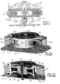
- the mixer shown in FIG. 1 has a base 1 having a flat plate 2 intended to be secured to a structure to calm.
- a coil 20 is secured to this base 1.
- a rod 23 carries at its two ends two flanges 3 and 24, one of which is secured to of the base 1 and the other 24 carries the coil 20.
- the moving part which comprises an upper pole piece 11, a lower pole piece 12 and a magnet 10 is mounted on a spring 22 and is centered by two springs of upper centering 31 and upper 32 mounted on a housing or salad bowl 40.
- the assembly defines an electrodynamic motor whose coil is fixed relative to the base 1 and have the moving part is a mass M b essentially constituted by the magnetic circuit, that is to say the pole pieces 11 and 12 and the magnet 10.
- a control circuit makes it possible to vary the value of a resistive load applied across the coil 20.
- This may be a variable resistance, for example a varistor, the value of which is function voltage, or else a rheostat controlled by the control device.
- We can thus vary the depreciation between two extremes, namely a very low damping by leaving the coil 20 in open circuit, or maximum damping by putting the coil 20 into short circuit, the load resistance then being equal to the component intrinsic resistive Ro of the coil 20.
- a relatively low or minimal damping is appropriate particularly to an aircraft in static flight, for which the vibrations have a established regime for which the drummer is given maximum effect, whereas a greater depreciation can be chosen when changing course to avoid transients that may destabilize the drummer and / or to raise the vibratory level in the cabin.
- the electrical independence coil Z b is connected to a load marked Z c .
- the mass M b is guided by two springs 31 and 32 disposed on either side of the ground circuit M b . They are integral at their center with an axis 23 secured to the base 1 and at their periphery of the ground circuit M b .
- FIG. 3 shows a centering spring 31, 32 made of metal, which has four blanks 50 (or through-holes) which form as many branches which are regularly distributed at 90 ° to the perimeter of an opening 55 and which extend from a internal end 53 near the central opening 55 of diameter D i and up to an outer end 54 near an outer contour 57 of diameter De.
- These cutouts 50 have a rounded profile convex towards the outside of the spring , in particular in the form of a spiral, and preferably of a parabolic spiral.
- the cuts 50 present preferentially a linear section 52 whose function is to avoid stress concentrations as will be explained below.
- the branches 50 form a little more than one turn of the perimeter of the spring between their ends 53 and 54.
- FIG. 4 represents an embodiment with 3 branches whose inner ends 63 are distributed at 90 ° around the periphery of a central opening of diameter Di and which evolve to an end 64 to near the outer contour 67 of diameter De.
- the profile is advantageously spiral, preferably parabolic. It spans a little more than a spring ride.
- a section linear end 62 is advantageously provided to prevent stress concentrations.
- the ends 53, 54, 63, 64 are sufficiently spaced openings 55, 65 and respective contours 57, 67 to allow a good fitting of the spring without concentration of constraints to these ends.
- the springs 31, 32 in the form of a stack of springs for example in the form of a laminated structure that is to say a stack of individual springs secured to each other for example by gluing. This allows you to change the axial stiffness that decreases with the number of layers, as well as the maximum stress reached.
- the preferred embodiment uses cutouts parabolic spiral (or along one or more approximate axes of a circle a spiral parabolic profile).
Landscapes
- Engineering & Computer Science (AREA)
- General Engineering & Computer Science (AREA)
- Mechanical Engineering (AREA)
- Physics & Mathematics (AREA)
- Aviation & Aerospace Engineering (AREA)
- Acoustics & Sound (AREA)
- Electromagnetism (AREA)
- Vibration Prevention Devices (AREA)
- Springs (AREA)
- Fluid-Damping Devices (AREA)
- Confectionery (AREA)
- Buildings Adapted To Withstand Abnormal External Influences (AREA)
- Apparatuses For Generation Of Mechanical Vibrations (AREA)
- Valve Device For Special Equipments (AREA)
- Dry Shavers And Clippers (AREA)
Description
- la figure 1 montre une vue schématique en coupe d'un dispositif selon l'invention,
- les figures 2a et 2b représentent respectivement en perspective et ne coupe un dispositif selon un mode de réalisation préféré de l'invention,
- la figure 3 montre une réalisation d'un ressort de centrage ("spider") à trois branches, et
- la figure 4 montre une réalisation d'un ressort de centrage ("spider") à quatre branches.
- il faut choisir un moteur électrodynamique dont les caractéristiques permettent de maximiser le rapport (BL)2 / Zb
- Zc doit être minimal (Zc = 0, soit un court-circuit franc)
- il suffit d'ouvrir le circuit électrique (Zc = ∝)
- les déplacements radiaux (selon les directions X et Y perpendiculaires à la direction Z)
- les rotations selon les axes X et Y
Claims (5)
- Dispositif d'amortissement de vibrations comprenant un dispositif de conversion d'énergie mécanique en énergie électrique monté sur une embase (2) destinée à être fixée sur une structure, ledit dispositif de conversion comportant un moteur électrodynamique ayant une bobine (20) reliée mécaniquement à l'embase, caractérisé en ce que ledit dispositif de conversion comporte en outre un circuit magnétique (10, 11, 12) suspendu par au moins un ressort (22), et en ce que la bobine (20) est couplée à une charge électrique présentant une composante résistive et présente un dispositif de commande (COM) pour faire varier la valeur de ladite composante résistive selon au moins deux valeurs.
- Dispositif selon la revendication 1, caractérisé en ce que le dispositif de commande (COM) présente une première valeur de commande de la composante résistive correspondant à un premier amortissement et une deuxième valeur de commande correspondant à un deuxième amortissement plus important.
- Dispositif selon la revendication 2, caractérisé en ce que, pour la première valeur de commande, la bobine (20) est en circuit ouvert.
- Dispositif selon une des revendications 2 ou 3, caractérisé en ce que, pour la deuxième valeur de commande, la bobine (20) est en court-circuit.
- Utilisation d'un dispositif d'amortissement selon une des revendications précédentes dans un aéronef, notamment un hélicoptère, caractérisé en ce qu'il met en oeuvre, à l'aide d'un calculateur de vol une commande du dispositif de commande selon la première valeur de commande lorsque l'aéronef est en vol statique et selon la deuxième valeur de commande lorsque l'aéronef est dans un état de changement de cap.
Applications Claiming Priority (3)
| Application Number | Priority Date | Filing Date | Title |
|---|---|---|---|
| FR0107352 | 2001-06-06 | ||
| FR0107352A FR2825769B1 (fr) | 2001-06-06 | 2001-06-06 | Dispositif d'amortissement de vibrations |
| PCT/FR2002/001925 WO2002099309A1 (fr) | 2001-06-06 | 2002-06-06 | Dispositif d'amortissement de vibrations |
Publications (2)
| Publication Number | Publication Date |
|---|---|
| EP1392987A1 EP1392987A1 (fr) | 2004-03-03 |
| EP1392987B1 true EP1392987B1 (fr) | 2005-08-03 |
Family
ID=8863977
Family Applications (1)
| Application Number | Title | Priority Date | Filing Date |
|---|---|---|---|
| EP02747509A Expired - Lifetime EP1392987B1 (fr) | 2001-06-06 | 2002-06-06 | Dispositif d'amortissement de vibrations |
Country Status (11)
| Country | Link |
|---|---|
| US (1) | US20030173725A1 (fr) |
| EP (1) | EP1392987B1 (fr) |
| JP (1) | JP2004521290A (fr) |
| CN (1) | CN1250889C (fr) |
| AT (1) | ATE301254T1 (fr) |
| CA (1) | CA2416010A1 (fr) |
| DE (1) | DE60205370T2 (fr) |
| DK (1) | DK1392987T3 (fr) |
| ES (1) | ES2247353T3 (fr) |
| FR (1) | FR2825769B1 (fr) |
| WO (1) | WO2002099309A1 (fr) |
Cited By (1)
| Publication number | Priority date | Publication date | Assignee | Title |
|---|---|---|---|---|
| WO2008131740A1 (fr) * | 2007-04-27 | 2008-11-06 | Fraunhofer-Gesellschaft zur Förderung der angewandten Forschung e.V. | Dispositif d'amortissement de vibrations |
Families Citing this family (35)
| Publication number | Priority date | Publication date | Assignee | Title |
|---|---|---|---|---|
| FR2856765B1 (fr) * | 2003-06-26 | 2005-12-02 | Hutchinson | Batteur dynamique actif |
| GB2439411B (en) * | 2007-04-27 | 2008-07-23 | Perpetuum Ltd | An electromechanical generator for converting mechanical vibrational energy into electrical energy |
| CN100564932C (zh) * | 2007-05-17 | 2009-12-02 | 中国科学技术大学 | 变刚度全主动动力吸振器 |
| GB2446685B (en) * | 2007-11-27 | 2009-04-01 | Perpetuum Ltd | An electromechanical generator for converting mechanical vibrational energy into electrical energy |
| CA2742798A1 (fr) | 2008-11-04 | 2010-05-14 | Lord Corporation | Generateur de force inertielle resonant a frequence propre stable |
| FR2945788B1 (fr) * | 2009-05-20 | 2011-05-13 | Eurocopter France | Dispositif a masses concentrees pour reduire les vibrations engendrees par un rotor de sustentation d'un giravion, et moyeu d'un rotor muni d'un tel dispositif |
| WO2010150385A1 (fr) * | 2009-06-25 | 2010-12-29 | パイオニア株式会社 | Amortisseur de vibrations et mécanisme d'amortissement |
| EP2915745B1 (fr) * | 2009-11-04 | 2017-12-13 | LORD Corporation | Actionneur inertiel électromagnétique |
| CA2779379A1 (fr) | 2009-11-04 | 2011-05-12 | Lord Corporation | Actionneur inertiel electromagnetique |
| US8188622B1 (en) * | 2009-11-12 | 2012-05-29 | The United States Of America, As Represented By The Secretary Of The Navy | Tunable resonant frequency kinetic energy harvester |
| WO2011061567A1 (fr) | 2009-11-20 | 2011-05-26 | La Nacion, Ministerio De Defensa, Fuerza Aerea Colombiana | Dispositif réducteur de vibrations au niveau du siège des pilotes d'hélicoptères |
| CN102011822B (zh) * | 2010-10-20 | 2013-03-20 | 哈尔滨工程大学 | 混合式隔振器 |
| KR101752645B1 (ko) | 2011-02-04 | 2017-06-30 | 로오드 코포레이션 | 공진 관성형 액추에이터를 구비한 회전익 항공기 진동 제어 시스템 |
| DE102011106127A1 (de) | 2011-06-10 | 2012-12-13 | Eads Deutschland Gmbh | Vorrichtung zur Reduzierung von Strukturschwingungen von Tragflügeln |
| CN103765033B (zh) * | 2011-08-18 | 2015-09-16 | Esm能源及振动技术沿有限公司 | 与温度无关的减振器 |
| JP5863528B2 (ja) | 2012-03-23 | 2016-02-16 | 三菱重工業株式会社 | 振動低減装置 |
| CN102733483A (zh) * | 2012-07-02 | 2012-10-17 | 大连理工大学 | 一种变刚度隔震一体化智能支座 |
| JP6060621B2 (ja) * | 2012-10-29 | 2017-01-18 | ミツミ電機株式会社 | 発電装置および発電システム |
| JP2014093841A (ja) * | 2012-11-02 | 2014-05-19 | Mitsumi Electric Co Ltd | 発電装置 |
| CN103016587B (zh) * | 2012-12-12 | 2015-04-01 | 上海交通大学 | 采用圆锥螺旋弹簧制成的半主动式变刚度动力吸振器 |
| KR101437363B1 (ko) * | 2013-01-07 | 2014-09-15 | 한국기계연구원 | 댐퍼 및 제너레이터용 댐퍼 |
| EP2857313B1 (fr) * | 2013-10-03 | 2015-12-23 | AGUSTAWESTLAND S.p.A. | Rotor d'un aéronef à voilure tournante comprenant un dispositif pour réduire les vibrations |
| CN103629302B (zh) * | 2013-11-29 | 2015-10-28 | 东风小康汽车有限公司重庆分公司 | 内平衡飞轮 |
| DE102013113347A1 (de) * | 2013-12-02 | 2015-06-03 | Airbus Defence and Space GmbH | Inertialkraftgenerator mit integriertem Haltemechanismus |
| CN105912044B (zh) * | 2016-06-06 | 2018-08-03 | 上海交通大学 | 频率分辨率可调谐动力吸振器 |
| CN107504125A (zh) * | 2017-09-23 | 2017-12-22 | 无锡工艺职业技术学院 | 一种机械设备减震装置 |
| TWI650627B (zh) * | 2017-10-27 | 2019-02-11 | 逢甲大學 | 雲台減振系統 |
| RU180588U1 (ru) * | 2017-11-14 | 2018-06-19 | Федеральное государственное казенное военное образовательное учреждение высшего профессионального образования "Военная академия материально-технического обеспечения имени генерала армии А.В. Хрулёва" Министерства обороны Российской Федерации | Усовершенствованный вибротермодатчик камертонного типа |
| CN108488552A (zh) * | 2018-03-30 | 2018-09-04 | 王宏伟 | 一种新型机械设备减震底座 |
| US10899437B2 (en) * | 2018-04-24 | 2021-01-26 | Bell Helicopter Textron Inc. | Planar vibration isolator |
| CN111355328A (zh) * | 2020-04-10 | 2020-06-30 | 中山市小美电器有限公司 | 电机、安装组件及减振件 |
| CN111412246A (zh) * | 2020-04-24 | 2020-07-14 | 扬州华交轨道交通科技有限公司 | 一种高速铁路减震器底座 |
| CN112610635A (zh) * | 2021-01-25 | 2021-04-06 | 深圳市佳键合科技有限公司 | 一种可根据震动强度自动调整减震行程的减震装置 |
| CN113048191B (zh) * | 2021-03-11 | 2022-07-15 | 哈尔滨工程大学 | 一种基于树木仿生的三维低频宽带地震超材料树 |
| CN114033833B (zh) * | 2021-11-29 | 2023-01-17 | 中国人民解放军海军工程大学 | 一种参数可调的高静低动刚度电磁隔振器 |
Family Cites Families (6)
| Publication number | Priority date | Publication date | Assignee | Title |
|---|---|---|---|---|
| US5293969A (en) * | 1991-02-14 | 1994-03-15 | Atsugi Unisia Corporation | Electromagnetic suspension device |
| FR2680848B1 (fr) * | 1991-08-29 | 1995-03-17 | Aerospatiale Ste Nat Indle | Procede et dispositif pour filtrer les excitations vibratoires transmises entre deux pieces, notamment entre le rotor et le fuselage d'un helicoptere. |
| DE19517630C2 (de) * | 1995-05-13 | 1997-10-09 | Metzeler Gimetall Ag | Aktiver Schwingungstilger |
| DE19621700C2 (de) * | 1996-05-30 | 2001-09-27 | Eurocopter Deutschland | Aktiver Schwingungsminderer |
| JP2000274482A (ja) * | 1999-01-18 | 2000-10-03 | Canon Inc | 能動的除振装置、露光装置及び方法並びにデバイス製造方法 |
| FR2825768B1 (fr) * | 2001-06-06 | 2004-03-12 | Vibrachoc Sa | Dispositif d'amortissement de vibrations |
-
2001
- 2001-06-06 FR FR0107352A patent/FR2825769B1/fr not_active Expired - Fee Related
-
2002
- 2002-06-06 WO PCT/FR2002/001925 patent/WO2002099309A1/fr not_active Ceased
- 2002-06-06 CA CA002416010A patent/CA2416010A1/fr not_active Abandoned
- 2002-06-06 DE DE60205370T patent/DE60205370T2/de not_active Expired - Lifetime
- 2002-06-06 ES ES02747509T patent/ES2247353T3/es not_active Expired - Lifetime
- 2002-06-06 JP JP2003502396A patent/JP2004521290A/ja active Pending
- 2002-06-06 EP EP02747509A patent/EP1392987B1/fr not_active Expired - Lifetime
- 2002-06-06 US US10/333,089 patent/US20030173725A1/en not_active Abandoned
- 2002-06-06 DK DK02747509T patent/DK1392987T3/da active
- 2002-06-06 CN CN02801960.1A patent/CN1250889C/zh not_active Expired - Fee Related
- 2002-06-06 AT AT02747509T patent/ATE301254T1/de not_active IP Right Cessation
Cited By (2)
| Publication number | Priority date | Publication date | Assignee | Title |
|---|---|---|---|---|
| WO2008131740A1 (fr) * | 2007-04-27 | 2008-11-06 | Fraunhofer-Gesellschaft zur Förderung der angewandten Forschung e.V. | Dispositif d'amortissement de vibrations |
| US8708115B2 (en) | 2007-04-27 | 2014-04-29 | Fraunhofer-Gesellschaft Zur Foerderung Der Angewandten Forschung E.V. | Device for damping vibrations |
Also Published As
| Publication number | Publication date |
|---|---|
| DE60205370D1 (de) | 2005-09-08 |
| DK1392987T3 (da) | 2005-12-05 |
| FR2825769A1 (fr) | 2002-12-13 |
| ES2247353T3 (es) | 2006-03-01 |
| US20030173725A1 (en) | 2003-09-18 |
| CA2416010A1 (fr) | 2002-12-12 |
| CN1250889C (zh) | 2006-04-12 |
| ATE301254T1 (de) | 2005-08-15 |
| EP1392987A1 (fr) | 2004-03-03 |
| FR2825769B1 (fr) | 2004-08-27 |
| CN1463338A (zh) | 2003-12-24 |
| DE60205370T2 (de) | 2006-06-01 |
| WO2002099309A1 (fr) | 2002-12-12 |
| JP2004521290A (ja) | 2004-07-15 |
Similar Documents
| Publication | Publication Date | Title |
|---|---|---|
| EP1392987B1 (fr) | Dispositif d'amortissement de vibrations | |
| EP1315917B1 (fr) | Dispositif d'amortissement de vibrations | |
| EP2256039B1 (fr) | Pivot traversant à éléments flexibles et engin spatial comportant un tel pivot | |
| EP2503641B1 (fr) | Système d'actionnement pour réflecteur d'antenne à surface réfléchissante déformable | |
| FR2770826A1 (fr) | Pale de rotor a volet orientable | |
| EP0608675B1 (fr) | Moteur électrique de puissance élevée et à vitesse de rotation élevée | |
| FR2959547A1 (fr) | Poulie de decouplage. | |
| FR2734034A1 (fr) | Dispositif de decouplage, notamment poulie decoupleuse, destine a un vehicule automobile | |
| FR3046436A1 (fr) | Convertisseur electrostatique. | |
| FR2772447A1 (fr) | Amortisseur comportant une soupape bidirectionnelle et un passage de limitation d'ecoulement parallele a la soupape | |
| EP1964778B1 (fr) | Pivot traversant à lames | |
| FR3043155A1 (fr) | Absorbeur de vibration, mecanisme d'amortissement et ensemble de propulsion associes | |
| BE1022436B1 (fr) | Rotor eolien de type savonius | |
| FR3128266A1 (fr) | Motoréducteur et cycle associé | |
| WO2017072338A1 (fr) | Absorbeur de vibration | |
| EP2724945A2 (fr) | Système de motorisation pour articulation à pistes de roulement flexibles | |
| WO2020025343A1 (fr) | Poulie à flasque à écartement variable pour variateur de vitesse | |
| EP0387135B1 (fr) | Dispositif de tension d'une courroie de transmission de puissance | |
| FR2837034A1 (fr) | Element de torsion piezoceramique et actionneur de torsion realise a partir de celui-ci | |
| EP3796542A1 (fr) | Dispositif de conversion d'energie mecanique en energie electrique fonctionnant sur une gamme de frequence de vibration elargie | |
| EP4419803B1 (fr) | Support rotatif pour l'orientation d'un arbre supportant un panneau solaire | |
| EP4191847A1 (fr) | Transducteur electromagnetique pour la recuperation d'energie vibratoire | |
| EP0533586A1 (fr) | Dispositif de suspension élastique à raideurs différenciées pour le support d'un équipement | |
| FR3057927A1 (fr) | Amortisseur de torsion et vehicule automobile | |
| EP2480289A2 (fr) | Dispositif utilisant une membrane adaptee pour porter et deplacer une charge |
Legal Events
| Date | Code | Title | Description |
|---|---|---|---|
| PUAI | Public reference made under article 153(3) epc to a published international application that has entered the european phase |
Free format text: ORIGINAL CODE: 0009012 |
|
| 17P | Request for examination filed |
Effective date: 20021223 |
|
| AK | Designated contracting states |
Kind code of ref document: A1 Designated state(s): AT BE CH CY DE DK ES FI FR GB GR IE IT LI LU MC NL PT SE TR |
|
| AX | Request for extension of the european patent |
Extension state: AL LT LV MK RO SI |
|
| RIN1 | Information on inventor provided before grant (corrected) |
Inventor name: NOE, MATHIEU |
|
| GRAP | Despatch of communication of intention to grant a patent |
Free format text: ORIGINAL CODE: EPIDOSNIGR1 |
|
| GRAS | Grant fee paid |
Free format text: ORIGINAL CODE: EPIDOSNIGR3 |
|
| GRAA | (expected) grant |
Free format text: ORIGINAL CODE: 0009210 |
|
| AK | Designated contracting states |
Kind code of ref document: B1 Designated state(s): AT BE CH CY DE DK ES FI FR GB GR IE IT LI LU MC NL PT SE TR |
|
| PG25 | Lapsed in a contracting state [announced via postgrant information from national office to epo] |
Ref country code: TR Free format text: LAPSE BECAUSE OF FAILURE TO SUBMIT A TRANSLATION OF THE DESCRIPTION OR TO PAY THE FEE WITHIN THE PRESCRIBED TIME-LIMIT Effective date: 20050803 Ref country code: IE Free format text: LAPSE BECAUSE OF FAILURE TO SUBMIT A TRANSLATION OF THE DESCRIPTION OR TO PAY THE FEE WITHIN THE PRESCRIBED TIME-LIMIT Effective date: 20050803 Ref country code: NL Free format text: LAPSE BECAUSE OF FAILURE TO SUBMIT A TRANSLATION OF THE DESCRIPTION OR TO PAY THE FEE WITHIN THE PRESCRIBED TIME-LIMIT Effective date: 20050803 Ref country code: AT Free format text: LAPSE BECAUSE OF FAILURE TO SUBMIT A TRANSLATION OF THE DESCRIPTION OR TO PAY THE FEE WITHIN THE PRESCRIBED TIME-LIMIT Effective date: 20050803 |
|
| REG | Reference to a national code |
Ref country code: GB Ref legal event code: FG4D Free format text: NOT ENGLISH |
|
| REG | Reference to a national code |
Ref country code: CH Ref legal event code: EP |
|
| REG | Reference to a national code |
Ref country code: IE Ref legal event code: FG4D Free format text: LANGUAGE OF EP DOCUMENT: FRENCH |
|
| REF | Corresponds to: |
Ref document number: 60205370 Country of ref document: DE Date of ref document: 20050908 Kind code of ref document: P |
|
| REG | Reference to a national code |
Ref country code: CH Ref legal event code: NV Representative=s name: ISLER & PEDRAZZINI AG |
|
| REG | Reference to a national code |
Ref country code: SE Ref legal event code: TRGR |
|
| GBT | Gb: translation of ep patent filed (gb section 77(6)(a)/1977) |
Effective date: 20051028 |
|
| REG | Reference to a national code |
Ref country code: DK Ref legal event code: T3 |
|
| REG | Reference to a national code |
Ref country code: GR Ref legal event code: EP Ref document number: 20050403329 Country of ref document: GR |
|
| PG25 | Lapsed in a contracting state [announced via postgrant information from national office to epo] |
Ref country code: PT Free format text: LAPSE BECAUSE OF FAILURE TO SUBMIT A TRANSLATION OF THE DESCRIPTION OR TO PAY THE FEE WITHIN THE PRESCRIBED TIME-LIMIT Effective date: 20060103 |
|
| NLV1 | Nl: lapsed or annulled due to failure to fulfill the requirements of art. 29p and 29m of the patents act | ||
| REG | Reference to a national code |
Ref country code: ES Ref legal event code: FG2A Ref document number: 2247353 Country of ref document: ES Kind code of ref document: T3 |
|
| REG | Reference to a national code |
Ref country code: IE Ref legal event code: FD4D |
|
| PLBE | No opposition filed within time limit |
Free format text: ORIGINAL CODE: 0009261 |
|
| STAA | Information on the status of an ep patent application or granted ep patent |
Free format text: STATUS: NO OPPOSITION FILED WITHIN TIME LIMIT |
|
| PG25 | Lapsed in a contracting state [announced via postgrant information from national office to epo] |
Ref country code: MC Free format text: LAPSE BECAUSE OF NON-PAYMENT OF DUE FEES Effective date: 20060630 |
|
| 26N | No opposition filed |
Effective date: 20060504 |
|
| REG | Reference to a national code |
Ref country code: CH Ref legal event code: PCAR Free format text: ISLER & PEDRAZZINI AG;POSTFACH 1772;8027 ZUERICH (CH) |
|
| PG25 | Lapsed in a contracting state [announced via postgrant information from national office to epo] |
Ref country code: CY Free format text: LAPSE BECAUSE OF FAILURE TO SUBMIT A TRANSLATION OF THE DESCRIPTION OR TO PAY THE FEE WITHIN THE PRESCRIBED TIME-LIMIT Effective date: 20050803 |
|
| PGFP | Annual fee paid to national office [announced via postgrant information from national office to epo] |
Ref country code: DK Payment date: 20090625 Year of fee payment: 8 |
|
| PGFP | Annual fee paid to national office [announced via postgrant information from national office to epo] |
Ref country code: FI Payment date: 20090615 Year of fee payment: 8 Ref country code: LU Payment date: 20090612 Year of fee payment: 8 Ref country code: SE Payment date: 20090618 Year of fee payment: 8 |
|
| PGFP | Annual fee paid to national office [announced via postgrant information from national office to epo] |
Ref country code: CH Payment date: 20090617 Year of fee payment: 8 |
|
| PGFP | Annual fee paid to national office [announced via postgrant information from national office to epo] |
Ref country code: GR Payment date: 20090430 Year of fee payment: 8 |
|
| PGFP | Annual fee paid to national office [announced via postgrant information from national office to epo] |
Ref country code: BE Payment date: 20090715 Year of fee payment: 8 |
|
| BERE | Be: lapsed |
Owner name: *HUTCHINSON Effective date: 20100630 |
|
| PG25 | Lapsed in a contracting state [announced via postgrant information from national office to epo] |
Ref country code: FI Free format text: LAPSE BECAUSE OF NON-PAYMENT OF DUE FEES Effective date: 20100606 |
|
| REG | Reference to a national code |
Ref country code: DK Ref legal event code: EBP Ref country code: CH Ref legal event code: PL |
|
| EUG | Se: european patent has lapsed | ||
| PG25 | Lapsed in a contracting state [announced via postgrant information from national office to epo] |
Ref country code: CH Free format text: LAPSE BECAUSE OF NON-PAYMENT OF DUE FEES Effective date: 20100630 Ref country code: LI Free format text: LAPSE BECAUSE OF NON-PAYMENT OF DUE FEES Effective date: 20100630 |
|
| PG25 | Lapsed in a contracting state [announced via postgrant information from national office to epo] |
Ref country code: BE Free format text: LAPSE BECAUSE OF NON-PAYMENT OF DUE FEES Effective date: 20100630 Ref country code: GR Free format text: LAPSE BECAUSE OF NON-PAYMENT OF DUE FEES Effective date: 20110104 |
|
| PG25 | Lapsed in a contracting state [announced via postgrant information from national office to epo] |
Ref country code: DK Free format text: LAPSE BECAUSE OF NON-PAYMENT OF DUE FEES Effective date: 20100630 |
|
| PG25 | Lapsed in a contracting state [announced via postgrant information from national office to epo] |
Ref country code: SE Free format text: LAPSE BECAUSE OF NON-PAYMENT OF DUE FEES Effective date: 20100607 Ref country code: LU Free format text: LAPSE BECAUSE OF NON-PAYMENT OF DUE FEES Effective date: 20100606 |
|
| REG | Reference to a national code |
Ref country code: FR Ref legal event code: PLFP Year of fee payment: 14 |
|
| REG | Reference to a national code |
Ref country code: GR Ref legal event code: ML Ref document number: 20050403329 Country of ref document: GR Effective date: 20110104 |
|
| REG | Reference to a national code |
Ref country code: FR Ref legal event code: PLFP Year of fee payment: 15 |
|
| REG | Reference to a national code |
Ref country code: FR Ref legal event code: PLFP Year of fee payment: 16 |
|
| PGFP | Annual fee paid to national office [announced via postgrant information from national office to epo] |
Ref country code: DE Payment date: 20170621 Year of fee payment: 16 Ref country code: FR Payment date: 20170505 Year of fee payment: 16 Ref country code: GB Payment date: 20170620 Year of fee payment: 16 |
|
| PGFP | Annual fee paid to national office [announced via postgrant information from national office to epo] |
Ref country code: IT Payment date: 20170622 Year of fee payment: 16 |
|
| PGFP | Annual fee paid to national office [announced via postgrant information from national office to epo] |
Ref country code: ES Payment date: 20170724 Year of fee payment: 16 |
|
| REG | Reference to a national code |
Ref country code: DE Ref legal event code: R119 Ref document number: 60205370 Country of ref document: DE |
|
| GBPC | Gb: european patent ceased through non-payment of renewal fee |
Effective date: 20180606 |
|
| PG25 | Lapsed in a contracting state [announced via postgrant information from national office to epo] |
Ref country code: DE Free format text: LAPSE BECAUSE OF NON-PAYMENT OF DUE FEES Effective date: 20190101 Ref country code: IT Free format text: LAPSE BECAUSE OF NON-PAYMENT OF DUE FEES Effective date: 20180606 Ref country code: GB Free format text: LAPSE BECAUSE OF NON-PAYMENT OF DUE FEES Effective date: 20180606 Ref country code: FR Free format text: LAPSE BECAUSE OF NON-PAYMENT OF DUE FEES Effective date: 20180630 |
|
| REG | Reference to a national code |
Ref country code: ES Ref legal event code: FD2A Effective date: 20190916 |
|
| PG25 | Lapsed in a contracting state [announced via postgrant information from national office to epo] |
Ref country code: ES Free format text: LAPSE BECAUSE OF NON-PAYMENT OF DUE FEES Effective date: 20180607 |