EP1393143B1 - Cytometre de flux portatif - Google Patents
Cytometre de flux portatif Download PDFInfo
- Publication number
- EP1393143B1 EP1393143B1 EP01961840A EP01961840A EP1393143B1 EP 1393143 B1 EP1393143 B1 EP 1393143B1 EP 01961840 A EP01961840 A EP 01961840A EP 01961840 A EP01961840 A EP 01961840A EP 1393143 B1 EP1393143 B1 EP 1393143B1
- Authority
- EP
- European Patent Office
- Prior art keywords
- light
- fluid
- flow
- flow stream
- stream
- Prior art date
- Legal status (The legal status is an assumption and is not a legal conclusion. Google has not performed a legal analysis and makes no representation as to the accuracy of the status listed.)
- Expired - Lifetime
Links
Images






Classifications
-
- G—PHYSICS
- G01—MEASURING; TESTING
- G01N—INVESTIGATING OR ANALYSING MATERIALS BY DETERMINING THEIR CHEMICAL OR PHYSICAL PROPERTIES
- G01N15/00—Investigating characteristics of particles; Investigating permeability, pore-volume or surface-area of porous materials
- G01N15/10—Investigating individual particles
- G01N15/14—Optical investigation techniques, e.g. flow cytometry
- G01N15/1404—Handling flow, e.g. hydrodynamic focusing
-
- A—HUMAN NECESSITIES
- A61—MEDICAL OR VETERINARY SCIENCE; HYGIENE
- A61B—DIAGNOSIS; SURGERY; IDENTIFICATION
- A61B5/00—Measuring for diagnostic purposes; Identification of persons
- A61B5/15—Devices for taking samples of blood
- A61B5/150007—Details
- A61B5/150015—Source of blood
- A61B5/150022—Source of blood for capillary blood or interstitial fluid
-
- A—HUMAN NECESSITIES
- A61—MEDICAL OR VETERINARY SCIENCE; HYGIENE
- A61B—DIAGNOSIS; SURGERY; IDENTIFICATION
- A61B5/00—Measuring for diagnostic purposes; Identification of persons
- A61B5/15—Devices for taking samples of blood
- A61B5/150007—Details
- A61B5/150015—Source of blood
- A61B5/15003—Source of blood for venous or arterial blood
-
- A—HUMAN NECESSITIES
- A61—MEDICAL OR VETERINARY SCIENCE; HYGIENE
- A61B—DIAGNOSIS; SURGERY; IDENTIFICATION
- A61B5/00—Measuring for diagnostic purposes; Identification of persons
- A61B5/15—Devices for taking samples of blood
- A61B5/150007—Details
- A61B5/150206—Construction or design features not otherwise provided for; manufacturing or production; packages; sterilisation of piercing element, piercing device or sampling device
- A61B5/150221—Valves
-
- A—HUMAN NECESSITIES
- A61—MEDICAL OR VETERINARY SCIENCE; HYGIENE
- A61B—DIAGNOSIS; SURGERY; IDENTIFICATION
- A61B5/00—Measuring for diagnostic purposes; Identification of persons
- A61B5/15—Devices for taking samples of blood
- A61B5/150007—Details
- A61B5/150343—Collection vessels for collecting blood samples from the skin surface, e.g. test tubes, cuvettes
-
- A—HUMAN NECESSITIES
- A61—MEDICAL OR VETERINARY SCIENCE; HYGIENE
- A61B—DIAGNOSIS; SURGERY; IDENTIFICATION
- A61B5/00—Measuring for diagnostic purposes; Identification of persons
- A61B5/15—Devices for taking samples of blood
- A61B5/150007—Details
- A61B5/150351—Caps, stoppers or lids for sealing or closing a blood collection vessel or container, e.g. a test-tube or syringe barrel
-
- A—HUMAN NECESSITIES
- A61—MEDICAL OR VETERINARY SCIENCE; HYGIENE
- A61B—DIAGNOSIS; SURGERY; IDENTIFICATION
- A61B5/00—Measuring for diagnostic purposes; Identification of persons
- A61B5/15—Devices for taking samples of blood
- A61B5/150007—Details
- A61B5/150801—Means for facilitating use, e.g. by people with impaired vision; means for indicating when used correctly or incorrectly; means for alarming
- A61B5/150809—Means for facilitating use, e.g. by people with impaired vision; means for indicating when used correctly or incorrectly; means for alarming by audible feedback
-
- A—HUMAN NECESSITIES
- A61—MEDICAL OR VETERINARY SCIENCE; HYGIENE
- A61B—DIAGNOSIS; SURGERY; IDENTIFICATION
- A61B5/00—Measuring for diagnostic purposes; Identification of persons
- A61B5/15—Devices for taking samples of blood
- A61B5/150007—Details
- A61B5/150801—Means for facilitating use, e.g. by people with impaired vision; means for indicating when used correctly or incorrectly; means for alarming
- A61B5/150824—Means for facilitating use, e.g. by people with impaired vision; means for indicating when used correctly or incorrectly; means for alarming by visual feedback
-
- A—HUMAN NECESSITIES
- A61—MEDICAL OR VETERINARY SCIENCE; HYGIENE
- A61B—DIAGNOSIS; SURGERY; IDENTIFICATION
- A61B5/00—Measuring for diagnostic purposes; Identification of persons
- A61B5/15—Devices for taking samples of blood
- A61B5/157—Devices characterised by integrated means for measuring characteristics of blood
-
- B—PERFORMING OPERATIONS; TRANSPORTING
- B01—PHYSICAL OR CHEMICAL PROCESSES OR APPARATUS IN GENERAL
- B01L—CHEMICAL OR PHYSICAL LABORATORY APPARATUS FOR GENERAL USE
- B01L3/00—Containers or dishes for laboratory use, e.g. laboratory glassware; Droppers
- B01L3/50—Containers for the purpose of retaining a material to be analysed, e.g. test tubes
- B01L3/502—Containers for the purpose of retaining a material to be analysed, e.g. test tubes with fluid transport, e.g. in multi-compartment structures
- B01L3/5027—Containers for the purpose of retaining a material to be analysed, e.g. test tubes with fluid transport, e.g. in multi-compartment structures by integrated microfluidic structures, i.e. dimensions of channels and chambers are such that surface tension forces are important, e.g. lab-on-a-chip
-
- G—PHYSICS
- G01—MEASURING; TESTING
- G01N—INVESTIGATING OR ANALYSING MATERIALS BY DETERMINING THEIR CHEMICAL OR PHYSICAL PROPERTIES
- G01N15/00—Investigating characteristics of particles; Investigating permeability, pore-volume or surface-area of porous materials
- G01N15/10—Investigating individual particles
- G01N15/14—Optical investigation techniques, e.g. flow cytometry
- G01N2015/1486—Counting the particles
-
- Y—GENERAL TAGGING OF NEW TECHNOLOGICAL DEVELOPMENTS; GENERAL TAGGING OF CROSS-SECTIONAL TECHNOLOGIES SPANNING OVER SEVERAL SECTIONS OF THE IPC; TECHNICAL SUBJECTS COVERED BY FORMER USPC CROSS-REFERENCE ART COLLECTIONS [XRACs] AND DIGESTS
- Y10—TECHNICAL SUBJECTS COVERED BY FORMER USPC
- Y10T—TECHNICAL SUBJECTS COVERED BY FORMER US CLASSIFICATION
- Y10T436/00—Chemistry: analytical and immunological testing
- Y10T436/10—Composition for standardization, calibration, simulation, stabilization, preparation or preservation; processes of use in preparation for chemical testing
- Y10T436/101666—Particle count or volume standard or control [e.g., platelet count standards, etc.]
Definitions
- the present invention relates generally to flow cytometers. More particularly, the present invention relates to portable flow cytometers that sense optical properties of microscopic biological particles in a flow stream.
- Flow cytometry is a technique that is used to determine certain physical and chemical properties of microscopic biological particles by sensing certain optical properties of the particles. To do so, the particles are arranged in single file using hydrodynamic focussing within a sheath fluid. The particles are then individually interrogated by a light beam. Each particle scatters the light beam and produces a scatter profile. The scatter profile is often identified by measuring the light intensity at different scatter angles. Certain physical and/or chemical properties of each particle can then be determined from the scatter profile.
- Flow cytometry is currently used in a wide variety of applications including hematology, immunology, genetics, food science, pharmacology, microbiology, parasitology and oncology, to name a few.
- a limitation of many commercially available flow cytometer systems is that they are relatively large bench top instruments that must remain in a central laboratory environment. Accordingly, the use of such flow cytometers is often not available in remote locations or for continuous hematological monitoring.
- WO-A-99/60397 relates to an apparatus and method for storing a particle-containing liquid.
- a microfluidic analysis cartridge (160) is provided having a convoluted storage channel (20) therein.
- the sample analysis can use optical, electrical, pressure sensitive, or flow sensitive detection
- a plurality of analysis channels (24A-24B) can be included in a single cartridge (160)
- the analysis channels (24A-24B) can be joined to reagent inlets for diluents, indicators or lysing agents.
- a mixing channel (80) can be positioned between the reagent Inlet and the analysis region (30) to allow mixing and reaction of the reagent.
- the cartridge (160) can include additional valves (V1-V5) and pumps (P11-P15) for flow management.
- the present invention overcomes many of the disadvantages of the prior art by providing a portable or wearable cytometer that can be used at remote locations, such as at home or in the field. Such a flow cytometer may help improve healthcare of patients by providing detailed individual hematological evaluation and uncovering statistical trends. By detecting an infection early, the infection may be more readily treatable.
- a portable cytometer as defined in claim 1.
- a method as defined in claim 9.
- the portable cytometer of the present invention may help save lives by providing early detection of infection due to biological agents. It is known that expanded activity in the biological sciences has increased the probability of accidental exposure to dangerous biological agents. The ease of manufacturing such agents also raises a serious threat to their use by terrorists, regional powers or developing third world nations. The lack of safeguards in international agreements outlawing biological warfare, and compelling evidence that those agreements may have been violated, reinforces the need for a strong capability for biological defense. During Desert Storm, American forces were not prepared to operate in a biological environment. Pre-exposure detection of pathogen agents, as well as post-exposure detection of incipient infections had to be used cooperatively to ensure efficient protection during biological warfare.
- the white blood cell count increases at the onset of infection.
- white blood cells There are several types of white blood cells including neutrophils, lymphocytes, monocytes, eosinophils and basofils. Lymphocytes create antibodies that attack the invaders and mark them for destruction by the neutrophils and macrophages.
- an increase in the percentage of lymphocytes in the overall white cell count is an indication of a viral infection.
- an increase in the percentage of the neutrophils is an indication of a developing bacterial infection.
- a clear infection warning can be issued with differentiation between viral or bacterial causes.
- the first clinical symptoms of infection from some bacterial agents such as bacillus anthrax appear after one to six days. In 99% of the cases, patients showing symptoms from anthrax cannot be treated, and will most likely die. However, if treatment is given before the first symptoms appear, most patients can be successfully treated. Accordingly, it would be highly desirable to provide an early alert and potential therapeutic intervention for hematologic abnormalities before symptoms occur. In many cases, such an early alert and treatment may greatly improve the outcome for many patients.
- a portable cytometer for identifying and/or counting selected particles in a fluid sample such as a blood sample.
- a portable cytometer includes a fluid receiver for receiving the fluid sample.
- One or more reservoirs are provided for storing supporting fluids such as lyse and sheath fluids.
- a precision fluid driving system is used for providing precise pressures to the fluids. A limitation of this approach is that precision fluid driving systems can be bulky, complex and may require significant power.
- the present invention uses a non-precision fluid driver that is controlled by a closed loop feedback path.
- the non-precision fluid driver is coupled to the fluid receiver and the various supporting fluid reservoirs, and applies separate pressures to the sample fluid and the supporting fluids.
- one or more valves are coupled to the fluid driver. The valves are used to regulate the non-precision pressures that are applied to the sample fluid and the supporting fluids by the non-precision fluid driver.
- flow sensors are provided downstream of the fluid driver to measure the fluid velocity of the sample fluid and the supporting fluids.
- a controller or processor receives the signals from the flow sensors, and adjusts the appropriate valves so that the desired fluid velocities of the sample fluid and supporting fluids are achieved.
- the flow sensors are preferably thermal anemometer type flow sensors.
- the non-precision fluid driver is manually powered.
- a manually powered fluid driver may include, for example, a bulb with check valve or a plunger.
- the manually generated pressure is preferably provided to a first pressure chamber.
- a first valve is then provided for controllably releasing the pressure in the first pressure chamber to a second pressure chamber.
- a second valve may be provided in the second pressure chamber for controllably venting the pressure in the second pressure chamber.
- the controller opens the first valve when the fluid flow in the downstream fluid stream drops below a first predetermined value and opens the second valve when the fluid flow in the downstream fluid stream increases above a second predetermined value.
- Each valve is preferably an array of electrostatically actuated microvalves that are individually addressable and controllable.
- the controlled sample fluid and supporting fluids are provided to a fluidic circuit.
- the fluidic circuit performs hydrodynamic focusing, which causes the desired particles to fall into single file along a core stream surrounded by a sheath fluid.
- One or more light sources provide light through the flow stream, and one or more light detectors detect the scatter profile of the particles in the flow stream.
- a processing block uses the output signals from the light detectors to identify and/or count selected particles in the core stream.
- the portable cytometer may be provided in a housing sufficiently small to be "wearable".
- the housing is sized similar to a wrist watch.
- the wearable housing may include, for example, a base, a cover, and a hinge that secures the base to the cover.
- the non-precision fluid driver and regulating valves may be incorporated into the cover, while the fluid reservoirs, flow sensors and fluidic circuit may be incorporated into a removable cartridge that is inserted into the housing.
- the fluidic circuit dilutes the blood sample, performs red cell lysing, and performs hydrodynamic focusing for flow and core stream formation.
- the light sources are preferably situated in either the base or the cover, and aligned with the flow stream of the removable cartridge.
- the light detectors are preferably provided generally opposite the light sources.
- the processor and batteries may be provided in either the base or the cover of the housing.
- the light sources may include a linear array of first light sources along a first light source axis.
- the first light source axis is preferably rotated relative to the central axis of the flow stream.
- a lens may be provided adjacent each light source to focus the light at the particles in the core stream.
- a first set of light detectors may then be placed in-line with each of the light source. Such an arrangement can be used to determine, for example, the alignment and width of the core stream within the flow stream. If the core stream of particles is not in proper alignment, the controller can adjust the fluid velocity of the sample fluid or one of the supporting fluids to bring the core stream into alignment.
- the first set of light detectors may also be used to detect the velocity and size of each particle, as well as the number of particles.
- a second set of the light sources may be provided along a second light source axis.
- a lens may be provided adjacent each light source to focus the light at the particles in the core stream.
- a second set of light detectors may then be placed on either side of the in-line position of each light source for measuring the small angle scattering (SALS) produced by selected particles in the flow stream.
- SALS small angle scattering
- the second set of light sources may also be used in conjunction with the first set of light sources to determine the time-of-flight or velocity of the particles in the flow stream. By knowing the velocity of the particles, small variations in the flow rate caused by the fluid driver can be minimized or removed by the controller.
- a third set of light sources may be provided along a third light source axis.
- a lens may be provided adjacent each light source to provide collimated light to the flow stream.
- Annular light detectors are then preferably placed opposite the light sources for measuring the forward angle scattering (FALS) produced by the selected particles in the flow stream.
- Each of the first, second and third set of light sources preferably include an array of lasers such as Vertical Cavity Surface Emitting Lasers (VCSEL) fabricated on a common substrate.
- VCSEL Vertical Cavity Surface Emitting Lasers
- Each of the first, second and third set of light detectors preferably include an array of photo detectors such as p-i-n photodiodes, GaAs photodiodes with integrated FET circuits, Resonant Cavity Photo Detectors (RCPD), or any other suitable light detector.
- the selected particles are preferably neutrophils and/or lymphocytes white blood cells.
- the portable cytometer of the present invention preferably identifies and counts the neutrophils and lymphocytes in a blood sample, and provide a clear infection warning with differentiation between viral and bacterial causes.
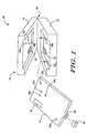
- FIG. 1 is a perspective view of an illustrative portable cytometer in accordance with the present invention.
- the portable cytometer is generally shown at 10, and includes a housing 12 and a removable or replaceable cartridge 14.
- the illustrative housing 12 includes a base 16, a cover 18, and a hinge 20 that attaches the base 16 to the cover 18.
- the base 16 includes an array of light sources 22, associated optics and the necessary electronics for operation of the cytometer.
- the cover 12 includes a manual pressurizing element, pressure-chambers with control microvalves, and an array of light detectors 24 with associated optics.
- the removable cartridge 14 preferably receives a sample fluid via a sample collector port 32.
- a cap 38 may be used to protect the sample collector port 32 when the removable cartridge 14 is not in use.
- the removable cartridge 14 preferably performs blood dilution, red cell lysing, and hydrodynamic focusing for core formation.
- the removable cartridge 14 may be constructed similar to the fluidic circuits available from Micronics Technologies, some of which are fabricated using a laminated structure with etched channels.
- the removable cartridge 14 is inserted into the housing when the cover 18 is in the open position.
- the removable cartridge 14 may include holes 26a and 26b for receiving registration pins 28a and 28b in the base 16, which help provide alignment and coupling between the different parts of the instrument.
- the removable cartridge 14 also preferably includes a transparent flow stream window 30, which is in alignment with the array of the light sources 22 and light detectors 24.
- the cover 18 is lifted and a new cartridge 14 is placed and registered onto the base 16.
- a blood sample is introduced into the sample collector 32.
- the cover 18 is closed and the system is manually pressurized. Once pressurized, the instrument performs a white blood cell cytometry measurement.
- the removable cartridge 14 provides blood dilution, red cell lysing, and hydrodynamic focusing for core formation.
- the light sources 22, light detectors 24 and associated control and processing electronics perform differentiation and counting of white blood cells based on light scattering signals. Rather than using a hinged construction for the housing 12, it is contemplated that a sliding cartridge slot or any other suitable construction may be used.
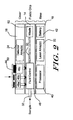
- Figure 2 is a schematic view of the illustrative portable cytometer of Figure 1.
- the base 16 may include an array of light sources 22, associated optics and also includes the necessary control and processing electronics 40 for operation of the cytometer.
- the base 16 may also include a battery 42 for powering the cytometer.
- the cover 12 is shown having a manual pressurizing element 44, pressure-chambers 46a, 46b and 46c with control microvalves, and an array of light detectors 24 with associated optics.
- the removable cartridge 14 may receive a sample fluid via the sample collector port 32. When pressurized by the cover 18, the removable cartridge 14 performs blood dilution, red cell lysing, and hydrodynamic focusing for core formation in a preferred embodiment.
- the core is provided down a flow stream path 50, which passes the flow stream window 30 of Figure 1.
- the array of light sources 22 and associated optics in the base provide light through the core stream via the flow stream window 30.
- the array of light detectors and associated optics receive scattered and non-scattered light from the core, also via the flow stream window 30.
- the controller or processor 40 receives output signals from the array of detectors, and differentiates and counts selected white blood cells that are present in the core stream.
- the removable cartridge 14 includes a fluid control block 48 which controls the velocity of each of the fluids.
- the fluid control block 48 includes flow sensors for sensing the velocity of the various fluids and report the velocities to the controller or processor 40. The controller or processor 40 may then adjust the microvalves associated with pressure-chambers 46a, 46b and 46c to achieve the desired pressures and thus desired fluid velocities for proper operation of the cytometer.
- the removable cartridge 14 preferably has a waste reservoir 52 downstream of the flow stream window 30.
- the waste reservoir 52 receives and stores the fluid of the flow stream in the removable cartridge 14.
- the removable cartridge may be removed and disposed of, preferably in a container compatible with biological waste.
- Figure 3 is a more detailed schematic diagram showing the portable cytometer of Figure 2 with the cover 18 not yet depressed.
- Figure 4 is a more detailed schematic diagram showing the portable cytometer of Figure 2 with the cover depressed.
- the cover 18 is shown having a manual pressurizing element 44, pressure-chambers 46a, 46b and 46c, and control microvalves generally shown at 60.
- the array of light sources and detectors are not shown in these Figures.
- pressure chamber 46a provides pressure to a blood sample reservoir 62
- pressure chamber 46b provides pressure to a lyse reservoir 64
- pressure chamber 46c provides pressure to a sheath reservoir 66.
- the size and shape of each pressure chamber 46a, 46b and 46c may be tailored to provide the desired pressure characteristics to the corresponding fluid.
- Pressure chamber 46a includes a first pressure chamber 70 and a second pressure chamber 72.
- a first valve 74 is provided between the first pressure chamber 70 and the second pressure chamber 72 for controllably releasing the pressure in the first pressure chamber 70 to a second pressure chamber 72.
- a second valve 76 in fluid communication with the second pressure chamber 72, controllably vents the pressure in the second pressure chamber 72.
- Each valve is preferably an array of electrostatically actuated microvalves that are individually addressable and controllable, as described in, for example, co-pending U.S. Patent Application Serial Number 09/404,560, entitled “ADDRESSABLE VALVE ARRAYS FOR PROPORTIONAL PRESSURE OR FLOW CONTROL", and incorporated herein by reference.
- Pressure chambers 46b and 46c include similar valves to control the pressures applied to the lyse reservoir 64 and sheath reservoir 66, respectively.
- each valve may be an array of electrostatically actuated microvalves that are pulse modulated with a controllable duty cycle to achieve a controlled "effective" flow or leak rate.
- the removable cartridge 14 has pressure receiving ports 34a, 34b, and 34c for receiving the controlled pressures from the cover 18.
- the controlled pressures are provided to the blood reservoir 62, lyse reservoir 64 and sheath reservoir 66, as shown.
- the lyse reservoir 64 and sheath reservoir 66 are preferably filled before the removable cartridge 14 is shipped for use, while the blood reservoir 62 is filled from sample collector port 32.
- a blood sample may be provided to the sample collector port 32, and through capillary action, the blood sample is sucked into the blood reservoir 62. Once the blood sample is in the blood reservoir 62, the cover 18 may be closed and the system may be pressurized.
- a flow sensor is provided in-line with each fluid prior to hydrodynamic focussing.
- Each flow sensor 80, 100 and 102 measures the velocity of the corresponding fluid.
- the flow sensors are preferably thermal anemometer type flow sensors, and more preferably microbridge type flow sensor.
- Microbridge flow sensors are described in, for example, U.S. Patent No. 4,478,076, U.S. Patent No. 4,478,077, U.S. Patent No. 4,501,144, U.S. Patent No. 4,651,564, U.S. Patent No.4,683,159, and U.S. Patent No. 5,050429, all of which are incorporated herein by reference.
- An output signal from each flow sensor 80, 100 and 102 is provided to controller or processor 40.
- the controller or processor 40 opens the first valve 74 when the velocity of the blood sample drops below a first predetermined value and opens the second valve 76 when the velocity of the blood sample increases above a second predetermined value.
- Valves 84, 86, 94 and 96 operate in a similar manner to control the velocities of the lyse and sheath fluids.
- the manual pressurizing element 44 During operation, and to pressurize the system, the manual pressurizing element 44 is depressed.
- the manual pressurizing element 44 includes three plungers, with each plunger received within a corresponding one of the first pressure chambers.
- the plungers create a relatively high non-precision pressure in the first pressure chambers.
- Lower, controlled pressures are built in the secondary chambers by opening the first valves 70, 84 and 94, which produce a controllable leak into the secondary chambers. If two much pressure builds up in the secondary pressure chambers, the corresponding vent valve 76, 86 and 96 are opened to relieve the pressure.
- the normally open first valves 74, 84 and 94 are closed while the vent valves 76, 86 and 96 are open.
- a predetermined pressure P is achieved in the first pressure chambers
- the vent valves 76, 86 and 96 are closed, and the first valves 74, 84 and 94 are opened to build a lower pressure P' in the secondary pressure chambers.
- the controlled pressure in the secondary pressure chambers provide the necessary pressures to the fluidic circuit of the removable cartridge 14 to produce fluid flow for the blood, lyse and sheath.
- the velocity of the fluid flow is then measured by the downstream flow sensors 80, 100 and 102.
- Each flow sensor provides an output signal that is used by the controller or processor 40 to control the operation of the corresponding first valve and vent valve to provide a desired and constant flow rate for each fluid.
- Downstream valves generally shown at 110 may also be provided. Controller or processor 40 may close downstream valves 110 until the system is pressurized. This may help prevent the blood, lyse and sheath from flowing into the fluid circuit before the circuit is pressurized. In another embodiment, downstream valves 110 are opened by mechanical action when the cover is closed.
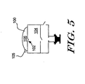
- FIG. 5 is a schematic diagram showing an illustrative manual fluid driver having a bulb 100 and check valve 102.
- the check valve 102 is preferably a one way valve that allows air in but not out of the first pressure chamber 104.
- the air in the interior 106 of the bulb 100 is forced through the check valve 102 and into the first pressure chamber 104.
- another a one-way vent valve 105 is provided that allows air in from the atmosphere but not out of the interior 106 of the bulb 100.
- the one-way vent valve 105 may allow replacement air to flow into bulb 100.
- any relatively small pressure source may be used including, for example, an electrostatically actuated meso-pump.
- meso-pump is described in, for example, U.S. Patent No. 5,836,750 to Cabuz, which is incorporated herein by reference.
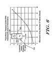
- Figure 6 is a graph showing proportional pressure control produced by a 8x7 addressable array of microvalves.
- 6.5 psi was applied to a first pressure chamber 120.
- a small opening was provided to a second pressure chamber 122.
- the microvalves are shown at 124, and vent the pressure in the second pressure chamber 122.
- the pressure in the second pressure chamber can be changed and controlled.
- the pressure in the second pressure chamber 122 could be changed from about 0.6 psi, when zero of the 8x7 array of microvalves closed, to about 6.5 psi, when all of the 8x7 array of microvalves are closed.
- These low power, micromachined silicon microvalves can be used for controlling pressures up to 10psi and beyond.
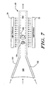
- FIG 7 is a schematic diagram showing the formation of a flow stream and core by the hydrodynamic focusing block 88 of Figure 3.
- the hydrodynamic focusing block 88 receives blood, lyse and sheath at controlled velocities from the fluid driver.
- the blood is mixed with the lyse, causing the red blood cells to be removed. This is often referred to as red cell lysing.
- the remaining white blood cells are provided down a central lumen 150, which is surrounded by sheath fluid to produce a flow stream 50.
- the flow stream 50 includes a core stream 160 surrounded by the sheath fluid 152.
- the dimensions of the channel are reduced as shown so that the white blood cells 154 and 156 are in single file.
- the velocity of the sheath fluid is preferably about 9 times that of the core stream 160. However, the velocity of the sheath fluid and core stream 160 remain sufficiently low to maintain laminar flow in the flow channel.
- Light emitters 22 and associated optics are preferably provided adjacent one side of the flow stream 50.
- Light detectors 24 and associated optics are provided on another side of the flow stream 50 for receiving the light from the light emitters 22 via the flow stream 50.
- the output signals from the light detectors 24 are provided to controller or processor 40, wherein they are analyzed to identify and/or count selected white blood cells in the core stream 160.
- Figure 8 is a schematic diagram showing an array of light sources and an array of light detectors for analysis of the core stream 160 of Figure 7.
- the light sources are shown as "+" signs and the detectors are shown at boxes.
- the array of light sources is provided adjacent one side of the flow stream 50, and the array of light detectors is provided adjacent the opposite side of the flow stream.
- Each of the light detectors is preferably aligned with a corresponding one of the light sources.
- the array of light sources and the array of light detectors are shown arranged along a light source axis 200 that is slightly rotated relative to the axis 202 of the flow stream 50.
- the array of light sources is preferably an array of lasers such as Vertical Cavity Surface Emitting Lasers (VCSEL) fabricated on a common substrate. Because of their vertical emission, VCSELs are ideally suited for packaging in compact instruments such as a portable cytometer. Preferably, the VCSELs are "red" VCSELs that operate at wavelengths that are less than the conventional 850 nm, and more preferably in the 670 nm to 780 nm range. Red VCSELs may have a wavelength, power and polarization characteristic that is ideally suited for scatter measurements.
- VCSEL Vertical Cavity Surface Emitting Lasers
- Some prior art cytometer bench models use a single 9mW edge-emitting laser with a wavelength of 650 nm.
- the beam is focussed to a 10x100 micron elongated shape to cover the uncertainty in particle position due to misalignment and width of the core stream.
- the output power of the red VCSELs of the present invention operating at 670 nm, is typically around 1 mW for a 10x10 micron emitter and 100-micron spacing.
- the total intensity of the light from a linear array of ten red VCSELs may be essentially the same as that of some prior art bench models.
- a linear array of lasers may be used to determining the lateral alignment of the path of the particles in the core steam.
- One source of uncertainty in the alignment of the particle stream is the width of the core flow, which leads to statistical fluctuations in the particle path position. These fluctuations can be determined from analysis of the detector data and can be used by the controller or processor 40 to adjust the valves of the fluid driver in order to change the relative pressures that are applied to the sample fluid and the supporting fluids to change the alignment of the selected particles in the flow stream.
- the cells pass through several focussed spots produced by the linear array of VCSELs.
- the cells produce a drop in signal in the corresponding in-line reference detectors.
- the relative strengths of the signals are used by the controller or processor 40 to determine the center of the particle path and a measure of the particle width.
- the lasers are preferably focussed to a series of Gaussian spots (intensity on the order of 1000W/cm 2 ) in the plane of the core flow.
- the spots are preferably about the same size as a white blood cell (10-12 um).
- Illustrative Gaussian spots are shown in Figure 9.
- Arrays of detectors and their focussing optics are provided on the opposite side of the fluid stream. Lenses with fairly large F-numbers are used to provide a working space of several hundred microns for the cytometer section of the removable cartridge.
- Particle velocity can be an important parameter in estimating the particle size from light scatter signals. In conventional cytometry, the particle velocity is extrapolated from the pump flow rates.
- a limitation of this approach is that the pumps must be very precise, the tolerance of the cytometer flow chambers must be tightly controlled, no fluid failures such as leaks can occur, and no obstructions such as microbubbles can be introduced to disturb the flow or core formation.
- the system may measure the time required for each cell to pass between two adjacent or successive spots. For example, and with reference to Figure 8, a cell may pass detector 208 and then detector 210. By measuring the time required for the cell to travel from detector 208 to detector 210, and by knowing the distance from detector 208 to detector 210, the controller or processor 40 can calculate the velocity of the cell. This would be an approximate velocity measurement. This is often referred to as a time-of-flight measurement. Once the velocity is known, the time of travel through the spot on which the particle is centered (a few microseconds) may provide a measure of particle length and size.
- the particle velocity can also be used to help control the fluid driver.
- the replaceable cartridge of Figure 1 may be manufactured from a plastic laminate or molded parts. While such manufacturing techniques may provide inexpensive parts, they are typically less dimensionally precise and repeatable, with asymmetrical dimensions and wider tolerance cross-sections. These wider tolerances may produce variations in particle velocity, particularly from cartridge to cartridge.
- the time-of-flight measurement discussed above can be used by the controller or processor 40 to adjust the controlled pressures applied to the blood, lyse and sheath fluid streams such that the particles in the core stream have a relatively constant velocity.
- laser beams may be focused both along the cell path and across the cell path. Additionally, multiple samples across the cell may be analyzed for texture features, to correlate morphological features to other cell types. This may provide multiple parameters about cell size that may help separate cell types from one another.
- Another advantage of using a linear array of lasers rather than a single layer configuration is that a relatively constant light illumination may be provided across the flow channel. This is accomplished by overlapping the Gaussian beams from adjacent VCSELs, as shown in Figure 9. In prior art single laser systems, the light illumination across the flow channel typically varies across the channel. Thus, if a particle is not in the center of the flow channel, the accuracy of subsequent measurements may be diminished.
- each detector in Figure 8 may be a single in-line detector. To measure FALS and SALS scatter, however, each detector may further include two annular detectors disposed around the in-line detector, as shown in Figure 10.
- a VCSEL 218 is shown providing light in an upward direction. The light is provided through a lens 220, which focuses the light to a Gaussian spot in the plane of the core flow.
- lens 220 may be a microlens or the like, which is either separate from or integrated with the VCSEL 218.
- the light passes through the core flow, and is received by another lens 222, such as a diffractive optical element.
- Lens 222 provides the light to in-line detector 226 and annular detectors 228 and 230.
- the in-line detector 226 detects the light that is not significantly scattered by the particles in the core stream.
- Annular detector 228 detects the forward scatter (FALS) light
- annular detector 230 detects the small angle scatter (SALS) light.
- FALS forward scatter
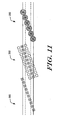
- Figure 11 shows another illustrative embodiment of the present invention that includes three separate arrays of light sources and light detectors.
- Each array of light sources and light detectors are positioned along a different light source axis that is slightly rotated relative to the central flow axis of the flow stream.
- the optics associated with each array may be optimized for a particular application or function. For detecting small angle scattering (SALS), laser light that is well-focussed on the plane of the core flow is desirable. For detecting forward scattering (FALS), collimated light is desirable.
- SALS small angle scattering
- FALS forward scattering
- a first array of light sources and light detectors is shown at 300.
- the light sources and light detectors are arranged in a linear array along a first light source axis.
- the first light source axis is rotated relative to the flow axis of the flow stream.
- the light sources and light detectors may be similar to that described above with respect to Figure 8, and preferably are used to measure, for example, the lateral alignment of the cells in the flow stream. the particle size, and the velocity of the particles.
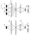
- Figure 12 is a schematic diagram showing an illustrative light source and detector pair of the first array 300 shown in Figure 11.
- a VCSEL 302 is shown providing light in an upward direction. The light is provided through a lens 304, which focuses the light to a Gaussian spot in the plane of the core flow. The light passes through the core flow, and is received by another lens 306. Lens 306 provides the light to in-line detector 308. The in-line detector 308 detects the light that is not significantly scattered by the particles in the core stream.
- a second array of light sources and light detectors is shown at 310.
- the light sources are arranged in a linear array along a second light source axis that is rotated relative to the flow axis of the flow stream.
- the light detectors include three linear arrays of light detectors. One array of light detectors is positioned in line with the linear array of light sources. The other two linear arrays of light detectors are placed on either side of the in-line array of light detectors, and are used for measuring the small angle scattering (SALS) produced by selected particles in the flow stream.
- SALS small angle scattering
- FIG 13 is a schematic diagram showing an illustrative light source and corresponding detectors of the second array shown in Figure 11.
- a VCSEL 320 is shown providing light in an upward direction. The light is provided through a lens 322, which focuses the light to a Gaussian spot in the plane of the core flow. The light passes through the core flow, and is received by another lens 324, such as a diffractive optical element (DOE) 324. Lens 324 provides the light to the in-line detector 326 and the two corresponding light detectors 328 and 330 placed on either side of the in-line light detector 326.
- DOE diffractive optical element
- the in-line detector 326 may be used to detect the light that is not significantly scattered by the particles in the core stream.
- the in-line linear array of light detectors of the second array 302 may be used to provide the same measurements as the in-line array of detectors of the first array 300. The measurements of both in-line arrays of detectors may be compared or combined to provide a more accurate result.
- the in-line detectors of the second array 302 may be used as a redundant set of detectors to improve the reliability of the cytometer.
- the in-line detectors of the second array 302 may also be used in conjunction with the in-line detectors of the first array 300 to more accurately determine the time-of-flight or velocity of the particles in the flow stream.
- the measurement may be more accurate because the distance between detectors may be greater.
- Light detectors 328 and 330 of Figure 13 are used to measure the small angle scattering (SALS) produced by selected particles in the flow stream.
- the light detectors 328 and 330 are therefore preferably spaced sufficiently from the in-line detector 326 to intercept the small angle scattering (SALS) produced by selected particles in the flow stream.
- a third array of light sources and light detectors 350 is preferably provided to measure the forward angle scattering (FALS) produced by selected particles in the flow stream.
- the light sources are arranged in a linear array along a third light source axis that is rotated relative to the flow axis of the flow stream.
- Each light source preferably has a corresponding light detector, and each light detector is preferably annular shaped with a non-sensitive region or a separate in-line detector in the middle.
- the annular shaped light detectors are preferably sized to intercept and detect the forward angle scattering (FALS) produced by selected particles in the flow stream.
- FIG 14 is a schematic diagram showing an illustrative light source and detector pair of the third array of light sources and light detectors 350 shown in Figure 11.
- a VCSEL 360 is shown providing light in an upward direction.
- the light is provided through a lens 362 such as a collimating lens, which provides substantially collimated light to the core flow. As indicated above, collimated light is desirable for detecting forward scattering (FALS) light.
- FALS forward scattering
- the light passes through the core flow, and is received by another lens 364.
- Lens 364 provides the received light to the annular shaped detector 368.
- the annular shaped detector 378 is preferably sized to intercept and detect the forward angle scattering (FALS) produced by selected particles in the flow stream.
- FALS forward angle scattering
- a non-sensitive region or a separate in-line detector 370 may be provided in the middle of the annular shaped detector 368. If a separate in-line detector 370 is provided, it can be used to provide the same measurement as the in-line detectors of the first array 300 and/or second array 302. When so provided, the measurements from all three in-line arrays of detectors of first array 300, second array 302 and third array 350 may be compared or combined to provide an even more accurate result.
- the in-line detectors of the third array 302 may also be used as another level or redundancy to improve the reliability of the cytometer.
- the in-line detectors of the third array 350 may also be used in conjunction with the in-line detectors if the first array 300 and/or second array 302 to more accurately determine the time-of-flight or velocity of the particles in the flow stream.
- the measurement may be more accurate because the distance between detectors may be greater.
- the optics associated with each array can be optimized for the desired application.
- the optics associated with the first array 300 are designed to provide well-focussed laser light on the plane of the core flow. This helps provide resolution to the alignment, size and particle velocity measurements performed by the first array 300.
- the optics associated with the second array 302 are designed to provide well-focussed laser light on the plane of the core flow. Well focussed light is desirable when measuring the small angle scattering (SALS) produced by selected particles in the flow stream.
- the optics associated with the third array 350 are designed to provide collimated light to the core flow. As indicated above, collimated light is desirable when measuring forward angle scattering (FALS) produced by selected particles in the flow stream.
- FALS forward angle scattering
- FIG 15 is a perspective view of an illustrative embodiment of the portable cytometer of the present invention adapted to be worn around the wrist.
- the portable cytometer is shown at 400, and may be similar to that shown in Figure 1.
- a band 402 secures the portable cytometer 400 to the wrist of a user.
- the user may obtain a removable cartridge and provide a blood sample to the sample collector port 32 (see Figure 1) of the removable cartridge.
- the blood sample may be collected by, for example, a finger prick.
- the user may then insert the removable cartridge into the housing, and manually pressurize the system.
- the portable cytometer may then provide a reading that indicates if the user should seek medical treatment.
- the reading may be a visual reading, an audible sound or any other suitable indicator.
- a catheter 404 or the like may be inserted into a vein of the user and attached to the sample collector port 32. This may allow the system to automatically collect a blood sample from the user whenever a reading is desired.
- the portable cytometer may be implanted in the user, with the sample collector port 32 connected to a suitable blood supply.
Landscapes
- Health & Medical Sciences (AREA)
- Life Sciences & Earth Sciences (AREA)
- Engineering & Computer Science (AREA)
- General Health & Medical Sciences (AREA)
- Physics & Mathematics (AREA)
- Pathology (AREA)
- Animal Behavior & Ethology (AREA)
- Biomedical Technology (AREA)
- Heart & Thoracic Surgery (AREA)
- Medical Informatics (AREA)
- Molecular Biology (AREA)
- Surgery (AREA)
- Biophysics (AREA)
- Hematology (AREA)
- Public Health (AREA)
- Veterinary Medicine (AREA)
- Chemical & Material Sciences (AREA)
- Dermatology (AREA)
- Manufacturing & Machinery (AREA)
- Dispersion Chemistry (AREA)
- Analytical Chemistry (AREA)
- Biochemistry (AREA)
- General Physics & Mathematics (AREA)
- Immunology (AREA)
- Investigating Or Analysing Biological Materials (AREA)
- Peptides Or Proteins (AREA)
- Optical Measuring Cells (AREA)
Claims (10)
- Cytomètre portatif (10) pour identifier et/ou compter des particules sélectionnées dans un fluide échantillon, comprenant :un récepteur de fluide (32) pour recevoir le fluide échantillon ;au moins un réservoir (64) pour stocker un ou plusieurs fluides de support ;un circuit fluidique (88) pour recevoir le fluide échantillon et le ou les fluides de support venant du dispositif d'entraînement de fluide ; et pour former un flux d'écoulement (50) ;un moyen fournisseur de lumière (22) pour fournir une lumière à travers le flux d'écoulement (50) ;un moyen récepteur de lumière (24) pour recevoir la lumière venant du flux d'écoulement (50) et pour fournir au moins un signal en réponse à celle-ci; etun moyen de traitement (40) pour recevoir le au moins un signal venant du moyen récepteur de lumière (24) et pour identifier et/ou compter des particules sélectionnées à l'intérieur ;un dispositif d'entraînement de fluide à non-précision couplé au récepteur de fluide (32) et au au moins un réservoir (64), caractérisé en ce que le dispositif d'entraînement de fluide à non-précision est capable d'appliquer des pressions séparées sur le fluide échantillon et sur le ou les fluides de support afin de fournir une vitesse de fluide à chacun des fluides comprenant le fluide échantillon et le ou les fluides de support ;un moyen valve (74) couplé au dispositif d'entraînement du fluide pour réguler les pressions séparées qui sont appliquées sur le fluide échantillon et sur le ou les fluides de support ;au moins un capteur d'écoulement (80) pour mesurer la vitesse du fluide échantillon et du ou des fluides de support fournis par le dispositif d'entraînement de fluide ;un moyen de commande (40) couplé au moyen valve (74) et au au moins un capteur d'écoulement (80) pour une commande en boucle fermée du moyen valve (74) de façon à ce que les vitesses de fluide du fluide échantillon et de chacun du ou des fluides de support soient aux niveaux désirés.
- Cytomètre portatif (10) selon la revendication 1, le moyen de traitement (40) identifiant la vitesse des particules sélectionnées dans le flux d'écoulement (50).
- Cytomètre portatif (10) selon la revendication 1, le moyen de traitement (40) identifiant la taille des particules sélectionnées dans le flux d'écoulement (50).
- Cytomètre portatif (10) selon la revendication 1, le moyen de traitement (40) identifiant l'alignement des particules sélectionnées dans le flux d'écoulement (50).
- Cytomètre portatif (10) selon la revendication 1, comprenant :une cartouche amovible (14) pour recevoir le fluide échantillon et pour préparer le fluide échantillon pour l'analyse, y compris l'exécution de la focalisation hydrodynamique afin de former un flux d'écoulement (50) ayant un flux central (160) de particules, cette cartouche (14) comprenant le récepteur de fluide (32) et un ou plusieurs orifices récepteurs de pression (34) pour recevoir une ou plusieurs pressions contrôlées ;un boîtier (12) adapté pour recevoir la cartouche amovible (14), ledit boîtier (12) ayant :le dispositif d'entraînement de fluide à non-précision appliquant une pression contrôlée sur le ou les orifices récepteurs de pression (34) de la cartouche amovible (14),le moyen fournisseur de lumière (22) positionné à côté du flux d'écoulement de la cartouche amovible (14),deux moyens récepteurs de lumière (24) ou plus prévus à côté du flux d'écoulement de la cartouche amovible (14) pour recevoir la lumière du flux d'écoulement (50), et pour fournir au moins un signal en réponse à celle-ci.
- Cytomètre portatif selon la revendication 5, la cartouche amovible (14) comprenant :le au moins un réservoir (64) pour stocker un ou plusieurs fluides de support.
- Cytomètre portatif selon la revendication 5, dans lequelle moyen fournisseur de lumière (22) comprend un premier ensemble de sources lumineuses (302) positionnées le long d'un axe de sources lumineuses (200) qui est décalé par rapport à l'axe central (202) de l'écoulement du flux d'écoulement (50), la lumière du premier ensemble de sources lumineuses est focalisée à un plan central qui inclut l'axe central du flux d'écoulement (50) ; etle moyen récepteur de lumière (24) comprend un premier ensemble de détecteurs de lumière (308) pour recevoir la lumière du premier ensemble de sources lumineuses (302) après que la lumière passe à travers le flux d'écoulement (50).
- Cytomètre portatif selon la revendication 7, le premier ensemble de sources lumineuses (302) et le premier ensemble de détecteurs de lumière (308) étant utilisés pour détecter l'alignement de l'écoulement de particules sélectionnées par rapport à la largeur du flux d'écoulement (50), la vitesse des particules sélectionnées dans le flux d'écoulement (50), et/ou la taille des particules sélectionnées dans le flux d'écoulement (50).
- Procédé pour analyser des particules sélectionnées dans un flux de fluide, ce procédé comprenant :la production d'une pression non précise manuellement,
caractérisée par la production d'une pression contrôlée à partir de la pression non précise produite manuellement,la fourniture d'écoulement à un flux de fluide en utilisant la pression contrôlée et en réglant la pression contrôlée selon une vitesse de l'écoulement du flux de fluide,l'analyse des particules sélectionnées dans le flux de fluide. - Procédé selon la revendication 9, l'étape d'analyse comprenant la détermination de la diffusion aux petits angles (SALS) produite par les particules sélectionnées dans le flux d'écoulement (50) et/ou la diffusion aux angles avant (FALS) produite par les particules sélectionnées dans le flux d'écoulement (50).
Applications Claiming Priority (3)
| Application Number | Priority Date | Filing Date | Title |
|---|---|---|---|
| US630924 | 1984-07-16 | ||
| US09/630,924 US6597438B1 (en) | 2000-08-02 | 2000-08-02 | Portable flow cytometry |
| PCT/US2001/024118 WO2002010713A2 (fr) | 2000-08-02 | 2001-08-02 | Cytometre de flux portatif |
Publications (2)
| Publication Number | Publication Date |
|---|---|
| EP1393143A2 EP1393143A2 (fr) | 2004-03-03 |
| EP1393143B1 true EP1393143B1 (fr) | 2007-02-14 |
Family
ID=24529128
Family Applications (1)
| Application Number | Title | Priority Date | Filing Date |
|---|---|---|---|
| EP01961840A Expired - Lifetime EP1393143B1 (fr) | 2000-08-02 | 2001-08-02 | Cytometre de flux portatif |
Country Status (8)
| Country | Link |
|---|---|
| US (1) | US6597438B1 (fr) |
| EP (1) | EP1393143B1 (fr) |
| JP (1) | JP4748919B2 (fr) |
| CN (1) | CN1302274C (fr) |
| AT (1) | ATE354122T1 (fr) |
| AU (1) | AU2001283074A1 (fr) |
| DE (1) | DE60126680T2 (fr) |
| WO (1) | WO2002010713A2 (fr) |
Families Citing this family (148)
| Publication number | Priority date | Publication date | Assignee | Title |
|---|---|---|---|---|
| US20050233459A1 (en) * | 2003-11-26 | 2005-10-20 | Melker Richard J | Marker detection method and apparatus to monitor drug compliance |
| JP4773019B2 (ja) | 1999-11-08 | 2011-09-14 | ユニバーシティ オブ フロリダ リサーチ ファンデーション インコーポレーティッド | 薬物の服薬遵守を監視するためのマーカー検出の方法および器具 |
| US7485454B1 (en) | 2000-03-10 | 2009-02-03 | Bioprocessors Corp. | Microreactor |
| US7630063B2 (en) * | 2000-08-02 | 2009-12-08 | Honeywell International Inc. | Miniaturized cytometer for detecting multiple species in a sample |
| US7420659B1 (en) * | 2000-06-02 | 2008-09-02 | Honeywell Interantional Inc. | Flow control system of a cartridge |
| US7641856B2 (en) * | 2004-05-14 | 2010-01-05 | Honeywell International Inc. | Portable sample analyzer with removable cartridge |
| US7471394B2 (en) * | 2000-08-02 | 2008-12-30 | Honeywell International Inc. | Optical detection system with polarizing beamsplitter |
| US7262838B2 (en) * | 2001-06-29 | 2007-08-28 | Honeywell International Inc. | Optical detection system for flow cytometry |
| US7242474B2 (en) | 2004-07-27 | 2007-07-10 | Cox James A | Cytometer having fluid core stream position control |
| US8329118B2 (en) * | 2004-09-02 | 2012-12-11 | Honeywell International Inc. | Method and apparatus for determining one or more operating parameters for a microfluidic circuit |
| US7016022B2 (en) * | 2000-08-02 | 2006-03-21 | Honeywell International Inc. | Dual use detectors for flow cytometry |
| US7978329B2 (en) * | 2000-08-02 | 2011-07-12 | Honeywell International Inc. | Portable scattering and fluorescence cytometer |
| US8071051B2 (en) * | 2004-05-14 | 2011-12-06 | Honeywell International Inc. | Portable sample analyzer cartridge |
| US20060263888A1 (en) * | 2000-06-02 | 2006-11-23 | Honeywell International Inc. | Differential white blood count on a disposable card |
| US8518328B2 (en) * | 2005-12-27 | 2013-08-27 | Honeywell International Inc. | Fluid sensing and control in a fluidic analyzer |
| US7061595B2 (en) | 2000-08-02 | 2006-06-13 | Honeywell International Inc. | Miniaturized flow controller with closed loop regulation |
| US7000330B2 (en) * | 2002-08-21 | 2006-02-21 | Honeywell International Inc. | Method and apparatus for receiving a removable media member |
| US7277166B2 (en) * | 2000-08-02 | 2007-10-02 | Honeywell International Inc. | Cytometer analysis cartridge optical configuration |
| US6981947B2 (en) * | 2002-01-22 | 2006-01-03 | University Of Florida Research Foundation, Inc. | Method and apparatus for monitoring respiratory gases during anesthesia |
| US20050054942A1 (en) | 2002-01-22 | 2005-03-10 | Melker Richard J. | System and method for therapeutic drug monitoring |
| US7104963B2 (en) * | 2002-01-22 | 2006-09-12 | University Of Florida Research Foundation, Inc. | Method and apparatus for monitoring intravenous (IV) drug concentration using exhaled breath |
| CA2440785A1 (fr) * | 2001-04-10 | 2002-10-24 | Bioprocessors Corporation | Microdispositif de fermentation et procede de criblage a base de cellules |
| EP1405067A2 (fr) * | 2001-05-23 | 2004-04-07 | University Of Florida | Procede et appareil pour la detection de substances illicites |
| US7052854B2 (en) | 2001-05-23 | 2006-05-30 | University Of Florida Research Foundation, Inc. | Application of nanotechnology and sensor technologies for ex-vivo diagnostics |
| EP1393069A1 (fr) | 2001-05-24 | 2004-03-03 | The University Of Florida | Procede et appareil de detection de l'exposition a un environnement de fumee |
| AU2002318269A1 (en) * | 2001-07-18 | 2003-03-03 | The Regents Of The University Of Michigan | Gas-focusing flow cytometer cell and flow cytometer detection system with waveguide optics |
| US20070167853A1 (en) | 2002-01-22 | 2007-07-19 | Melker Richard J | System and method for monitoring health using exhaled breath |
| US7223371B2 (en) * | 2002-03-14 | 2007-05-29 | Micronics, Inc. | Microfluidic channel network device |
| US6808075B2 (en) | 2002-04-17 | 2004-10-26 | Cytonome, Inc. | Method and apparatus for sorting particles |
| EP1499453B1 (fr) * | 2002-04-17 | 2016-01-06 | Cytonome/ST, LLC | Appareil de tri de particules |
| US6976590B2 (en) | 2002-06-24 | 2005-12-20 | Cytonome, Inc. | Method and apparatus for sorting particles |
| US7157274B2 (en) * | 2002-06-24 | 2007-01-02 | Cytonome, Inc. | Method and apparatus for sorting particles |
| US9943847B2 (en) | 2002-04-17 | 2018-04-17 | Cytonome/St, Llc | Microfluidic system including a bubble valve for regulating fluid flow through a microchannel |
| US20070065808A1 (en) * | 2002-04-17 | 2007-03-22 | Cytonome, Inc. | Method and apparatus for sorting particles |
| US6877528B2 (en) | 2002-04-17 | 2005-04-12 | Cytonome, Inc. | Microfluidic system including a bubble valve for regulating fluid flow through a microchannel |
| FR2841653B1 (fr) * | 2002-06-26 | 2005-05-27 | Abx Sa | Procede et dispositif d'analyse d'un echantillon de sang |
| CA2468014C (fr) * | 2003-06-04 | 2016-03-22 | Abbott Rapid Diagnostics International Unlimited Company | Detection de flux permettant de determiner les resultats d'un essai |
| US7239394B2 (en) | 2003-06-04 | 2007-07-03 | Inverness Medical Switzerland Gmbh | Early determination of assay results |
| KR101135138B1 (ko) * | 2003-08-13 | 2012-04-16 | 루미넥스 코포레이션 | 유세포 분석기식 측정 시스템의 하나 이상의 파라미터의제어 방법 |
| US7431883B2 (en) | 2003-09-30 | 2008-10-07 | Beckman Coulter, Inc. | Clinical analysis system |
| JP4362532B2 (ja) | 2004-04-07 | 2009-11-11 | ウォードロウ パートナーズ エルピー | 生体液を分析する使い捨てチャンバ |
| DE102005052752A1 (de) | 2005-11-04 | 2007-05-10 | Clondiag Chip Technologies Gmbh | Vorrichtung und Verfahren zum Nachweis von molekularen Wechselwirkungen |
| US7773227B2 (en) * | 2004-06-04 | 2010-08-10 | California Institute Of Technology | Optofluidic microscope device featuring a body comprising a fluid channel and having light transmissive regions |
| US8097225B2 (en) * | 2004-07-28 | 2012-01-17 | Honeywell International Inc. | Microfluidic cartridge with reservoirs for increased shelf life of installed reagents |
| US7612871B2 (en) * | 2004-09-01 | 2009-11-03 | Honeywell International Inc | Frequency-multiplexed detection of multiple wavelength light for flow cytometry |
| US7630075B2 (en) | 2004-09-27 | 2009-12-08 | Honeywell International Inc. | Circular polarization illumination based analyzer system |
| US7333197B2 (en) * | 2004-11-17 | 2008-02-19 | Honeywell International Inc. | Raman detection based flow cytometer |
| US9260693B2 (en) | 2004-12-03 | 2016-02-16 | Cytonome/St, Llc | Actuation of parallel microfluidic arrays |
| CN101099082B (zh) * | 2004-12-03 | 2013-03-27 | 塞通诺米/St有限责任公司 | 用于粒子处理的整体式盒 |
| US7491502B2 (en) * | 2004-12-17 | 2009-02-17 | The General Hospital Corporation | In vivo flow cytometry system and method |
| US7264794B2 (en) * | 2004-12-17 | 2007-09-04 | The General Hospital | Methods of in vivo cytometry |
| US7328882B2 (en) * | 2005-01-06 | 2008-02-12 | Honeywell International Inc. | Microfluidic modulating valve |
| US7110192B2 (en) * | 2005-01-12 | 2006-09-19 | Dako Denmark A/S | System and method for a composite lens for a flow cytometer |
| US7445017B2 (en) * | 2005-01-28 | 2008-11-04 | Honeywell International Inc. | Mesovalve modulator |
| EP1868725B1 (fr) * | 2005-03-08 | 2012-01-18 | Authentix, Inc. | Utilisation d' un dispositif microfluidique pour la identification, quantification, et authentification de marqueurs latents |
| CA2507323A1 (fr) * | 2005-05-13 | 2006-11-13 | Chromedx Inc. | Appareil de diagnostic pour l'analyse du plasma et du sang total |
| US7288098B2 (en) | 2005-04-14 | 2007-10-30 | Ethicon Endo-Surgery, Inc. | Force limiting mechanism for medical instrument |
| US8523882B2 (en) | 2005-04-14 | 2013-09-03 | Ethicon Endo-Surgery, Inc. | Clip advancer mechanism with alignment features |
| US7740641B2 (en) | 2005-04-14 | 2010-06-22 | Ethicon Endo-Surgery, Inc. | Clip applier with migrational resistance features |
| US7297149B2 (en) | 2005-04-14 | 2007-11-20 | Ethicon Endo-Surgery, Inc. | Surgical clip applier methods |
| US8038686B2 (en) | 2005-04-14 | 2011-10-18 | Ethicon Endo-Surgery, Inc. | Clip applier configured to prevent clip fallout |
| US7261724B2 (en) | 2005-04-14 | 2007-08-28 | Ethicon Endo-Surgery, Inc. | Surgical clip advancement mechanism |
| US7686820B2 (en) | 2005-04-14 | 2010-03-30 | Ethicon Endo-Surgery, Inc. | Surgical clip applier ratchet mechanism |
| EP1875200A1 (fr) * | 2005-04-29 | 2008-01-09 | Honeywell International Inc. | Procede de comptage et de mesure de la taille de cellules utilisant un cytometre |
| US8361413B2 (en) * | 2005-06-09 | 2013-01-29 | The United States Of America, As Represented By The Secretary Of The Navy | Sheath flow device |
| US8361410B2 (en) | 2005-07-01 | 2013-01-29 | Honeywell International Inc. | Flow metered analyzer |
| CN101253401B (zh) | 2005-07-01 | 2013-01-02 | 霍尼韦尔国际公司 | 带三维流体动力学集中的模制标本盒 |
| JP4995197B2 (ja) * | 2005-07-01 | 2012-08-08 | ハネウェル・インターナショナル・インコーポレーテッド | 3d流体力学的集束を有する成形カートリッジ |
| US7517201B2 (en) * | 2005-07-14 | 2009-04-14 | Honeywell International Inc. | Asymmetric dual diaphragm pump |
| US7843563B2 (en) * | 2005-08-16 | 2010-11-30 | Honeywell International Inc. | Light scattering and imaging optical system |
| US20070045128A1 (en) * | 2005-08-19 | 2007-03-01 | Honeywell International Inc. | Chlorine dioxide sensor |
| US20070051415A1 (en) * | 2005-09-07 | 2007-03-08 | Honeywell International Inc. | Microvalve switching array |
| US7731901B2 (en) | 2005-10-19 | 2010-06-08 | Abbott Laboratories | Apparatus and method for performing counts within a biologic fluid sample |
| US7806604B2 (en) * | 2005-10-20 | 2010-10-05 | Honeywell International Inc. | Face detection and tracking in a wide field of view |
| JP5175213B2 (ja) | 2005-12-22 | 2013-04-03 | ハネウェル・インターナショナル・インコーポレーテッド | 携帯用サンプル分析システム |
| WO2007075920A2 (fr) * | 2005-12-22 | 2007-07-05 | Honeywell International Inc. | Systeme d'analyseur |
| WO2007075922A2 (fr) | 2005-12-22 | 2007-07-05 | Honeywell International Inc. | Cartouche pour analyseur d'echantillons portatif |
| US7485153B2 (en) * | 2005-12-27 | 2009-02-03 | Honeywell International Inc. | Fluid free interface for a fluidic analyzer |
| US8182767B2 (en) * | 2005-12-27 | 2012-05-22 | Honeywell International Inc. | Needle-septum interface for a fluidic analyzer |
| JP5431732B2 (ja) * | 2005-12-29 | 2014-03-05 | ハネウェル・インターナショナル・インコーポレーテッド | マイクロ流体フォーマットにおけるアッセイ実装 |
| US9041938B2 (en) | 2006-05-02 | 2015-05-26 | California Institute Of Technology | Surface wave assisted structures and systems |
| US7768654B2 (en) | 2006-05-02 | 2010-08-03 | California Institute Of Technology | On-chip phase microscope/beam profiler based on differential interference contrast and/or surface plasmon assisted interference |
| US7551278B2 (en) * | 2006-05-12 | 2009-06-23 | Honeywell International Inc. | Fluid light guide system |
| US7914460B2 (en) * | 2006-08-15 | 2011-03-29 | University Of Florida Research Foundation, Inc. | Condensate glucose analyzer |
| US8702976B2 (en) * | 2007-04-18 | 2014-04-22 | Ondavia, Inc. | Hand-held microfluidic testing device |
| WO2008137693A2 (fr) * | 2007-05-04 | 2008-11-13 | The General Hospital Corporation D/B/A Massachusetts General Hospital | Cytométrie d'écoulement rétinien |
| US20080290114A1 (en) * | 2007-05-25 | 2008-11-27 | Honeywell International Inc. | Drug Delivery Flow Controller |
| GB2450351B (en) | 2007-06-20 | 2012-01-18 | Cozart Bioscience Ltd | Monitoring an Immunoassay |
| JP4509154B2 (ja) * | 2007-09-04 | 2010-07-21 | ソニー株式会社 | 光照射装置、微粒子解析装置及び光照射方法 |
| CN101435764B (zh) * | 2007-11-12 | 2013-11-27 | 北京深迈瑞医疗电子技术研究院有限公司 | 一种粒子分析仪及粒子分析方法 |
| US8314933B2 (en) | 2008-03-04 | 2012-11-20 | California Institute Of Technology | Optofluidic microscope device with photosensor array |
| US8325349B2 (en) | 2008-03-04 | 2012-12-04 | California Institute Of Technology | Focal plane adjustment by back propagation in optofluidic microscope devices |
| US8574859B2 (en) * | 2008-03-27 | 2013-11-05 | The General Hospital Corporation | In vivo flow cytometry based on cellular autofluorescence |
| US8039776B2 (en) | 2008-05-05 | 2011-10-18 | California Institute Of Technology | Quantitative differential interference contrast (DIC) microscopy and photography based on wavefront sensors |
| US8094299B2 (en) * | 2008-07-24 | 2012-01-10 | Beckman Coulter, Inc. | Transducer module |
| US20100034704A1 (en) * | 2008-08-06 | 2010-02-11 | Honeywell International Inc. | Microfluidic cartridge channel with reduced bubble formation |
| US8037354B2 (en) | 2008-09-18 | 2011-10-11 | Honeywell International Inc. | Apparatus and method for operating a computing platform without a battery pack |
| US9034277B2 (en) | 2008-10-24 | 2015-05-19 | Honeywell International Inc. | Surface preparation for a microfluidic channel |
| US8233146B2 (en) * | 2009-01-13 | 2012-07-31 | Becton, Dickinson And Company | Cuvette for flow-type particle analyzer |
| EP2380055A4 (fr) | 2009-01-21 | 2012-07-11 | California Inst Of Techn | Dispositifs de contraste interférentiel différentiel quantitatif (dic) destinés au sectionnement calculé d'une profondeur |
| WO2010132053A1 (fr) | 2009-05-13 | 2010-11-18 | Indevr, Inc. | Mesure et commande de flux pour une quantification améliorée de particules dans une cytométrie de flux |
| DE102009040151B4 (de) * | 2009-05-26 | 2013-09-12 | Analytik Jena Ag | Anordnung zur Detektion von Chemolumineszenz an Gasen |
| US8416400B2 (en) | 2009-06-03 | 2013-04-09 | California Institute Of Technology | Wavefront imaging sensor |
| US8633432B2 (en) | 2009-09-21 | 2014-01-21 | California Institute Of Technology | Reflective focusing and transmissive projection device |
| US8262679B2 (en) | 2009-10-09 | 2012-09-11 | Ethicon Endo-Surgery, Inc. | Clip advancer |
| US8267945B2 (en) | 2009-10-09 | 2012-09-18 | Ethicon Endo-Surgery, Inc. | Clip advancer with lockout mechanism |
| US8767216B2 (en) | 2009-10-13 | 2014-07-01 | California Institute Of Technology | Holographically illuminated imaging devices |
| CN102762289B (zh) | 2009-12-18 | 2016-08-03 | 艾博特健康公司 | 生物流体分析卡盒 |
| US8970671B2 (en) | 2010-02-23 | 2015-03-03 | California Institute Of Technology | Nondiffracting beam detection devices for three-dimensional imaging |
| EP2550522B1 (fr) | 2010-03-23 | 2016-11-02 | California Institute of Technology | Microscopes optofluidiques super-résolution pour une imagerie en deux dimensions (2d) et en trois dimensions (3d) |
| US8536545B2 (en) | 2010-09-09 | 2013-09-17 | California Institute Of Technology | Delayed emission detection devices and methods |
| US9873118B2 (en) | 2010-12-30 | 2018-01-23 | Abbott Point Of Care, Inc. | Biologic fluid analysis cartridge with sample handling portion and analysis chamber portion |
| US9086536B2 (en) | 2011-03-09 | 2015-07-21 | California Institute Of Technology | Talbot imaging devices and systems |
| WO2012145566A2 (fr) | 2011-04-20 | 2012-10-26 | California Institute Of Technology | Dispositifs d'imagerie à éclairement talbot, systèmes et procédés d'ajustement du plan focal |
| CN102288531B (zh) * | 2011-04-21 | 2012-12-19 | 西北工业大学 | 过滤染色计数细胞的方法及装置 |
| CN103890590B (zh) | 2011-08-24 | 2016-03-09 | 艾博特健康公司 | 生物流体样品分析盒 |
| BR112014009401B1 (pt) | 2011-10-19 | 2021-02-17 | Ethicon Endo-Surgery, Inc. | instrumento de fixação cirúrgica |
| CN102507419B (zh) * | 2011-10-27 | 2013-07-03 | 江苏苏净集团有限公司 | 一种用于液体颗粒计数器的样品池及其制作方法 |
| US8741235B2 (en) | 2011-12-27 | 2014-06-03 | Honeywell International Inc. | Two step sample loading of a fluid analysis cartridge |
| US8741233B2 (en) | 2011-12-27 | 2014-06-03 | Honeywell International Inc. | Disposable cartridge for fluid analysis |
| US8741234B2 (en) | 2011-12-27 | 2014-06-03 | Honeywell International Inc. | Disposable cartridge for fluid analysis |
| US8663583B2 (en) | 2011-12-27 | 2014-03-04 | Honeywell International Inc. | Disposable cartridge for fluid analysis |
| CN104136922B (zh) * | 2012-02-04 | 2017-03-01 | 细胞和分子平台中心(C-Camp) | 一种微流体分析仪及其方法 |
| CN110579435B (zh) | 2012-10-15 | 2023-09-26 | 纳诺赛莱克特生物医药股份有限公司 | 颗粒分选的系统、设备和方法 |
| US8994941B2 (en) | 2012-11-28 | 2015-03-31 | General Electric Company | Optical system, apparatus and method for performing flow cytometry |
| US9207166B2 (en) * | 2013-01-31 | 2015-12-08 | Honeywell International Inc. | Micro-molded cytometer cartridge with integrated optics |
| US9636034B2 (en) * | 2013-10-23 | 2017-05-02 | Verily Life Sciences Llc | Non-invasive analyte detection system with modulation source |
| WO2015063540A1 (fr) * | 2013-10-28 | 2015-05-07 | Droguett Bizet Sara | Microdispositif de type laboratoire sur puce pour identifier la sensibilité antibiotique au centre de soins des patients |
| US9348322B2 (en) * | 2014-06-05 | 2016-05-24 | Google Technology Holdings LLC | Smart device including biometric sensor |
| CN104833620B (zh) * | 2015-04-20 | 2018-03-13 | 江苏苏净集团有限公司 | 一种大气颗粒物浓度的监测装置 |
| JP6714603B2 (ja) | 2015-10-09 | 2020-07-01 | シスメックス株式会社 | 検体処理チップ、検体処理装置および検体処理方法 |
| JP6998387B2 (ja) * | 2016-10-07 | 2022-01-18 | アコーソート アーベー | 分散流体における光学的または電気的測定のための方法およびシステム |
| US10098588B2 (en) * | 2017-02-12 | 2018-10-16 | Hoon Kim | Portable apparatus for noninvasively measuring blood glucose level and operating method thereof |
| CN106901706A (zh) * | 2017-03-10 | 2017-06-30 | 安徽通灵仿生科技有限公司 | 一种儿童手套式远程诊断系统 |
| WO2018175411A1 (fr) | 2017-03-20 | 2018-09-27 | Nanocellect Biomedical, Inc. | Systèmes, appareils et procédés de tri de cellules et cytométrie de flux |
| CN110869746B (zh) | 2017-08-17 | 2023-08-11 | 雅培医护站股份有限公司 | 利用通用电路系统执行光学和电化学测定的技术 |
| US11067526B2 (en) | 2017-08-17 | 2021-07-20 | Abbott Point Of Care Inc. | Devices, systems, and methods for performing optical and electrochemical assays |
| US11253852B2 (en) | 2017-08-17 | 2022-02-22 | Abbott Point Of Care Inc. | Devices, systems, and methods for performing optical assays |
| WO2020028639A1 (fr) | 2018-08-01 | 2020-02-06 | Essen Instruments, Inc. D/B/A Essen Bioscience, Inc. | Procédés, kits et compositions de coloration pour l'évaluation par cytométrie de flux de particules de taille virale non associées à l'aide de multiples colorants fluorogènes |
| US11137337B2 (en) | 2019-01-21 | 2021-10-05 | Essen Instruments, Inc. | Flow cytometry with data analysis for optimized dilution of fluid samples for flow cytometry investigation |
| EP3948279B1 (fr) | 2019-03-26 | 2025-06-18 | Sartorius BioAnalytical Instruments, Inc. | Évaluation par cytométrie en flux pour particules virales non enrobées non associées |
| US12590896B2 (en) | 2019-05-28 | 2026-03-31 | Robert A. Levine | Apparatus and method for transferring and analyzing suspended particles in a liquid sample |
| US12605525B2 (en) | 2019-12-04 | 2026-04-21 | Nextern Innovation, Llc | Focusing catheter |
| US11709116B2 (en) | 2020-02-04 | 2023-07-25 | Sartorius Bioanalytical Instruments, Inc. | Liquid flourescent dye concentrate for flow cytometry evaluation of virus-size particles and related products and methods |
| JP7780798B2 (ja) * | 2022-01-28 | 2025-12-05 | 国立大学法人福井大学 | マイクロチップ、微粒子分析装置及び計測装置 |
| JP2026500222A (ja) * | 2022-12-09 | 2026-01-06 | センシル インコーポレイテッド | スペクトルを撮像、感知、測定、および記録、するための装置、方法、およびシステム |
| US12584902B2 (en) | 2023-12-10 | 2026-03-24 | Instrumentation Laboratory Company | Acoustic separation of a test sample |
| CN120232951A (zh) * | 2023-12-29 | 2025-07-01 | 深圳市帝迈生物技术有限公司 | 粒子计数装置、粒子计数方法和血细胞计数装置 |
Family Cites Families (40)
| Publication number | Priority date | Publication date | Assignee | Title |
|---|---|---|---|---|
| US4478077A (en) | 1982-09-30 | 1984-10-23 | Honeywell Inc. | Flow sensor |
| US4478076A (en) | 1982-09-30 | 1984-10-23 | Honeywell Inc. | Flow sensor |
| US4651564A (en) | 1982-09-30 | 1987-03-24 | Honeywell Inc. | Semiconductor device |
| US4501144A (en) | 1982-09-30 | 1985-02-26 | Honeywell Inc. | Flow sensor |
| KR970007077B1 (ko) * | 1987-03-13 | 1997-05-02 | 코울터 일렉트로닉스 인커퍼레이티드 | 광산란 기술을 이용한 다중-부분식별 분석 방법 |
| JPS6453965A (en) * | 1987-05-29 | 1989-03-01 | Hiroaki Watanabe | Winding machine for strip material |
| JPS6453965U (fr) * | 1987-09-30 | 1989-04-03 | ||
| JPH0616037B2 (ja) * | 1988-02-01 | 1994-03-02 | 株式会社日立製作所 | 細胞診自動化撮影装置 |
| US5244537A (en) | 1989-12-27 | 1993-09-14 | Honeywell, Inc. | Fabrication of an electronic microvalve apparatus |
| US5082242A (en) | 1989-12-27 | 1992-01-21 | Ulrich Bonne | Electronic microvalve apparatus and fabrication |
| US5050429A (en) | 1990-02-22 | 1991-09-24 | Yamatake-Honeywell Co., Ltd. | Microbridge flow sensor |
| US5108623A (en) | 1990-11-19 | 1992-04-28 | Gould Inc. | Moving web filter assembly |
| US5176358A (en) | 1991-08-08 | 1993-01-05 | Honeywell Inc. | Microstructure gas valve control |
| US5441597A (en) | 1992-12-01 | 1995-08-15 | Honeywell Inc. | Microstructure gas valve control forming method |
| IL106662A (en) * | 1993-08-11 | 1996-10-31 | Yissum Res Dev Co | Install a flow cell to monitor blood or any single cell suspension under flow |
| GB9406551D0 (en) | 1994-03-31 | 1994-05-25 | Hjelm Nils M | Chromatography system and methodology |
| US5716852A (en) | 1996-03-29 | 1998-02-10 | University Of Washington | Microfabricated diffusion-based chemical sensor |
| US5932100A (en) | 1995-06-16 | 1999-08-03 | University Of Washington | Microfabricated differential extraction device and method |
| US5922210A (en) | 1995-06-16 | 1999-07-13 | University Of Washington | Tangential flow planar microfabricated fluid filter and method of using thereof |
| US5726751A (en) | 1995-09-27 | 1998-03-10 | University Of Washington | Silicon microchannel optical flow cytometer |
| JP3308441B2 (ja) * | 1995-12-19 | 2002-07-29 | シスメックス株式会社 | 尿中有形成分分析装置 |
| US5863502A (en) | 1996-01-24 | 1999-01-26 | Sarnoff Corporation | Parallel reaction cassette and associated devices |
| US5948684A (en) | 1997-03-31 | 1999-09-07 | University Of Washington | Simultaneous analyte determination and reference balancing in reference T-sensor devices |
| GB2312556B (en) * | 1996-04-24 | 1999-12-22 | Carel Martin Grove | Variable capacitor |
| JP3261493B2 (ja) * | 1996-04-25 | 2002-03-04 | 株式会社ユアテック | キャピラリー式光検出センサ及びこれを用いた光計測装置及び懸濁液中の微粒子測定方法 |
| DE69728269T2 (de) | 1996-06-14 | 2005-03-10 | University Of Washington, Seattle | Absorbtionsverbessertes differentielles extraktionsverfahren |
| US5764674A (en) | 1996-06-28 | 1998-06-09 | Honeywell Inc. | Current confinement for a vertical cavity surface emitting laser |
| US5799030A (en) | 1996-07-26 | 1998-08-25 | Honeywell Inc. | Semiconductor device with a laser and a photodetector in a common container |
| US5683159A (en) | 1997-01-03 | 1997-11-04 | Johnson; Greg P. | Hardware mounting rail |
| US5974867A (en) | 1997-06-13 | 1999-11-02 | University Of Washington | Method for determining concentration of a laminar sample stream |
| US6082185A (en) | 1997-07-25 | 2000-07-04 | Research International, Inc. | Disposable fluidic circuit cards |
| US6007775A (en) | 1997-09-26 | 1999-12-28 | University Of Washington | Multiple analyte diffusion based chemical sensor |
| US5822170A (en) | 1997-10-09 | 1998-10-13 | Honeywell Inc. | Hydrophobic coating for reducing humidity effect in electrostatic actuators |
| US5836750A (en) | 1997-10-09 | 1998-11-17 | Honeywell Inc. | Electrostatically actuated mesopump having a plurality of elementary cells |
| US6004821A (en) * | 1998-03-07 | 1999-12-21 | Levine; Robert A. | Method and apparatus for performing chemical, qualitative, quantitative, and semi-quantitative analyses of a urine sample |
| AU3530799A (en) * | 1998-05-13 | 1999-11-29 | Bayer Corporation | Optical spectroscopy sample cell |
| CA2320296A1 (fr) | 1998-05-18 | 1999-11-25 | University Of Washington | Cartouche d'analyse liquide |
| JP3522535B2 (ja) | 1998-05-29 | 2004-04-26 | 忠弘 大見 | 圧力式流量制御装置を備えたガス供給設備 |
| US6097485A (en) * | 1999-03-08 | 2000-08-01 | Integrated Waveguides, Inc. | Microchip optical transport technology for use in a personal flow cytometer |
| EP1242813A4 (fr) | 1999-07-28 | 2002-10-30 | Univ Washington | Systeme d'interconnexion pour fluides, tubulure d'interconnexion et dispositifs microfluidiques destines a la distribution interne de gaz et a l'application d'un vide |
-
2000
- 2000-08-02 US US09/630,924 patent/US6597438B1/en not_active Expired - Lifetime
-
2001
- 2001-08-02 DE DE60126680T patent/DE60126680T2/de not_active Expired - Lifetime
- 2001-08-02 EP EP01961840A patent/EP1393143B1/fr not_active Expired - Lifetime
- 2001-08-02 AU AU2001283074A patent/AU2001283074A1/en not_active Abandoned
- 2001-08-02 AT AT01961840T patent/ATE354122T1/de not_active IP Right Cessation
- 2001-08-02 CN CNB018167241A patent/CN1302274C/zh not_active Expired - Lifetime
- 2001-08-02 JP JP2002516593A patent/JP4748919B2/ja not_active Expired - Lifetime
- 2001-08-02 WO PCT/US2001/024118 patent/WO2002010713A2/fr not_active Ceased
Also Published As
| Publication number | Publication date |
|---|---|
| US6597438B1 (en) | 2003-07-22 |
| CN1502068A (zh) | 2004-06-02 |
| AU2001283074A1 (en) | 2002-02-13 |
| CN1302274C (zh) | 2007-02-28 |
| JP2004505272A (ja) | 2004-02-19 |
| DE60126680T2 (de) | 2007-11-15 |
| WO2002010713A2 (fr) | 2002-02-07 |
| WO2002010713A3 (fr) | 2003-12-24 |
| EP1393143A2 (fr) | 2004-03-03 |
| DE60126680D1 (de) | 2007-03-29 |
| ATE354122T1 (de) | 2007-03-15 |
| JP4748919B2 (ja) | 2011-08-17 |
Similar Documents
| Publication | Publication Date | Title |
|---|---|---|
| EP1393143B1 (fr) | Cytometre de flux portatif | |
| EP1828863B1 (fr) | Regulateur de debit miniaturise utilisant la regulation en boucle | |
| US7671987B2 (en) | Optical detection system for flow cytometry | |
| US6549275B1 (en) | Optical detection system for flow cytometry | |
| US7978329B2 (en) | Portable scattering and fluorescence cytometer | |
| US7471394B2 (en) | Optical detection system with polarizing beamsplitter | |
| US7420659B1 (en) | Flow control system of a cartridge | |
| US6382228B1 (en) | Fluid driving system for flow cytometry | |
| US7262838B2 (en) | Optical detection system for flow cytometry | |
| US6700130B2 (en) | Optical detection system for flow cytometry |
Legal Events
| Date | Code | Title | Description |
|---|---|---|---|
| PUAI | Public reference made under article 153(3) epc to a published international application that has entered the european phase |
Free format text: ORIGINAL CODE: 0009012 |
|
| 17P | Request for examination filed |
Effective date: 20030131 |
|
| AK | Designated contracting states |
Kind code of ref document: A2 Designated state(s): AT BE CH CY DE DK ES FI FR GB GR IE IT LI LU MC NL PT SE TR |
|
| GRAP | Despatch of communication of intention to grant a patent |
Free format text: ORIGINAL CODE: EPIDOSNIGR1 |
|
| GRAS | Grant fee paid |
Free format text: ORIGINAL CODE: EPIDOSNIGR3 |
|
| GRAA | (expected) grant |
Free format text: ORIGINAL CODE: 0009210 |
|
| AK | Designated contracting states |
Kind code of ref document: B1 Designated state(s): AT BE CH CY DE DK ES FI FR GB GR IE IT LI LU MC NL PT SE TR |
|
| PG25 | Lapsed in a contracting state [announced via postgrant information from national office to epo] |
Ref country code: LI Free format text: LAPSE BECAUSE OF FAILURE TO SUBMIT A TRANSLATION OF THE DESCRIPTION OR TO PAY THE FEE WITHIN THE PRESCRIBED TIME-LIMIT Effective date: 20070214 Ref country code: BE Free format text: LAPSE BECAUSE OF FAILURE TO SUBMIT A TRANSLATION OF THE DESCRIPTION OR TO PAY THE FEE WITHIN THE PRESCRIBED TIME-LIMIT Effective date: 20070214 Ref country code: AT Free format text: LAPSE BECAUSE OF FAILURE TO SUBMIT A TRANSLATION OF THE DESCRIPTION OR TO PAY THE FEE WITHIN THE PRESCRIBED TIME-LIMIT Effective date: 20070214 Ref country code: CH Free format text: LAPSE BECAUSE OF FAILURE TO SUBMIT A TRANSLATION OF THE DESCRIPTION OR TO PAY THE FEE WITHIN THE PRESCRIBED TIME-LIMIT Effective date: 20070214 Ref country code: FI Free format text: LAPSE BECAUSE OF FAILURE TO SUBMIT A TRANSLATION OF THE DESCRIPTION OR TO PAY THE FEE WITHIN THE PRESCRIBED TIME-LIMIT Effective date: 20070214 Ref country code: NL Free format text: LAPSE BECAUSE OF FAILURE TO SUBMIT A TRANSLATION OF THE DESCRIPTION OR TO PAY THE FEE WITHIN THE PRESCRIBED TIME-LIMIT Effective date: 20070214 Ref country code: DK Free format text: LAPSE BECAUSE OF FAILURE TO SUBMIT A TRANSLATION OF THE DESCRIPTION OR TO PAY THE FEE WITHIN THE PRESCRIBED TIME-LIMIT Effective date: 20070214 |
|
| REG | Reference to a national code |
Ref country code: GB Ref legal event code: FG4D |
|
| REG | Reference to a national code |
Ref country code: CH Ref legal event code: EP |
|
| REF | Corresponds to: |
Ref document number: 60126680 Country of ref document: DE Date of ref document: 20070329 Kind code of ref document: P |
|
| REG | Reference to a national code |
Ref country code: IE Ref legal event code: FG4D |
|
| PG25 | Lapsed in a contracting state [announced via postgrant information from national office to epo] |
Ref country code: SE Free format text: LAPSE BECAUSE OF FAILURE TO SUBMIT A TRANSLATION OF THE DESCRIPTION OR TO PAY THE FEE WITHIN THE PRESCRIBED TIME-LIMIT Effective date: 20070514 |
|
| PG25 | Lapsed in a contracting state [announced via postgrant information from national office to epo] |
Ref country code: ES Free format text: LAPSE BECAUSE OF FAILURE TO SUBMIT A TRANSLATION OF THE DESCRIPTION OR TO PAY THE FEE WITHIN THE PRESCRIBED TIME-LIMIT Effective date: 20070525 |
|
| PG25 | Lapsed in a contracting state [announced via postgrant information from national office to epo] |
Ref country code: PT Free format text: LAPSE BECAUSE OF FAILURE TO SUBMIT A TRANSLATION OF THE DESCRIPTION OR TO PAY THE FEE WITHIN THE PRESCRIBED TIME-LIMIT Effective date: 20070716 |
|
| ET | Fr: translation filed | ||
| NLV1 | Nl: lapsed or annulled due to failure to fulfill the requirements of art. 29p and 29m of the patents act | ||
| REG | Reference to a national code |
Ref country code: CH Ref legal event code: PL |
|
| PLBE | No opposition filed within time limit |
Free format text: ORIGINAL CODE: 0009261 |
|
| STAA | Information on the status of an ep patent application or granted ep patent |
Free format text: STATUS: NO OPPOSITION FILED WITHIN TIME LIMIT |
|
| 26N | No opposition filed |
Effective date: 20071115 |
|
| PG25 | Lapsed in a contracting state [announced via postgrant information from national office to epo] |
Ref country code: IT Free format text: LAPSE BECAUSE OF FAILURE TO SUBMIT A TRANSLATION OF THE DESCRIPTION OR TO PAY THE FEE WITHIN THE PRESCRIBED TIME-LIMIT Effective date: 20070214 Ref country code: MC Free format text: LAPSE BECAUSE OF NON-PAYMENT OF DUE FEES Effective date: 20070831 Ref country code: GR Free format text: LAPSE BECAUSE OF FAILURE TO SUBMIT A TRANSLATION OF THE DESCRIPTION OR TO PAY THE FEE WITHIN THE PRESCRIBED TIME-LIMIT Effective date: 20070515 |
|
| PG25 | Lapsed in a contracting state [announced via postgrant information from national office to epo] |
Ref country code: IE Free format text: LAPSE BECAUSE OF NON-PAYMENT OF DUE FEES Effective date: 20070802 |
|
| PG25 | Lapsed in a contracting state [announced via postgrant information from national office to epo] |
Ref country code: CY Free format text: LAPSE BECAUSE OF FAILURE TO SUBMIT A TRANSLATION OF THE DESCRIPTION OR TO PAY THE FEE WITHIN THE PRESCRIBED TIME-LIMIT Effective date: 20070214 |
|
| PG25 | Lapsed in a contracting state [announced via postgrant information from national office to epo] |
Ref country code: LU Free format text: LAPSE BECAUSE OF NON-PAYMENT OF DUE FEES Effective date: 20070802 |
|
| PG25 | Lapsed in a contracting state [announced via postgrant information from national office to epo] |
Ref country code: TR Free format text: LAPSE BECAUSE OF FAILURE TO SUBMIT A TRANSLATION OF THE DESCRIPTION OR TO PAY THE FEE WITHIN THE PRESCRIBED TIME-LIMIT Effective date: 20070214 |
|
| REG | Reference to a national code |
Ref country code: FR Ref legal event code: PLFP Year of fee payment: 15 |
|
| REG | Reference to a national code |
Ref country code: FR Ref legal event code: PLFP Year of fee payment: 16 |
|
| REG | Reference to a national code |
Ref country code: FR Ref legal event code: PLFP Year of fee payment: 17 |
|
| REG | Reference to a national code |
Ref country code: FR Ref legal event code: PLFP Year of fee payment: 18 |
|
| PGFP | Annual fee paid to national office [announced via postgrant information from national office to epo] |
Ref country code: DE Payment date: 20200827 Year of fee payment: 20 Ref country code: FR Payment date: 20200824 Year of fee payment: 20 Ref country code: GB Payment date: 20200825 Year of fee payment: 20 |
|
| REG | Reference to a national code |
Ref country code: DE Ref legal event code: R071 Ref document number: 60126680 Country of ref document: DE |
|
| REG | Reference to a national code |
Ref country code: GB Ref legal event code: PE20 Expiry date: 20210801 |
|
| PG25 | Lapsed in a contracting state [announced via postgrant information from national office to epo] |
Ref country code: GB Free format text: LAPSE BECAUSE OF EXPIRATION OF PROTECTION Effective date: 20210801 |
|
| P01 | Opt-out of the competence of the unified patent court (upc) registered |
Effective date: 20230523 |