EP1393777A1 - Tete de potelet - Google Patents
Tete de potelet Download PDFInfo
- Publication number
- EP1393777A1 EP1393777A1 EP03356127A EP03356127A EP1393777A1 EP 1393777 A1 EP1393777 A1 EP 1393777A1 EP 03356127 A EP03356127 A EP 03356127A EP 03356127 A EP03356127 A EP 03356127A EP 1393777 A1 EP1393777 A1 EP 1393777A1
- Authority
- EP
- European Patent Office
- Prior art keywords
- post
- post head
- head according
- frustoconical
- support member
- Prior art date
- Legal status (The legal status is an assumption and is not a legal conclusion. Google has not performed a legal analysis and makes no representation as to the accuracy of the status listed.)
- Granted
Links
- 230000000903 blocking effect Effects 0.000 claims description 9
- 238000005260 corrosion Methods 0.000 claims description 4
- 238000006073 displacement reaction Methods 0.000 claims description 4
- 210000002105 tongue Anatomy 0.000 claims description 4
- 230000000295 complement effect Effects 0.000 claims description 3
- 230000007797 corrosion Effects 0.000 claims description 3
- 238000012423 maintenance Methods 0.000 claims description 3
- 230000001681 protective effect Effects 0.000 claims description 3
- 238000003780 insertion Methods 0.000 claims description 2
- 230000037431 insertion Effects 0.000 claims description 2
- 230000001419 dependent effect Effects 0.000 claims 1
- 238000007789 sealing Methods 0.000 claims 1
- 238000004873 anchoring Methods 0.000 description 7
- 238000009434 installation Methods 0.000 description 3
- 235000001674 Agaricus brunnescens Nutrition 0.000 description 1
- 241001272720 Medialuna californiensis Species 0.000 description 1
- 229910000831 Steel Inorganic materials 0.000 description 1
- HCHKCACWOHOZIP-UHFFFAOYSA-N Zinc Chemical compound [Zn] HCHKCACWOHOZIP-UHFFFAOYSA-N 0.000 description 1
- 238000005246 galvanizing Methods 0.000 description 1
- 238000004519 manufacturing process Methods 0.000 description 1
- 239000007769 metal material Substances 0.000 description 1
- 230000002265 prevention Effects 0.000 description 1
- 239000002994 raw material Substances 0.000 description 1
- 239000007787 solid Substances 0.000 description 1
- 239000010959 steel Substances 0.000 description 1
- 239000011701 zinc Substances 0.000 description 1
- 229910052725 zinc Inorganic materials 0.000 description 1
Images


Classifications
-
- A—HUMAN NECESSITIES
- A62—LIFE-SAVING; FIRE-FIGHTING
- A62B—DEVICES, APPARATUS OR METHODS FOR LIFE-SAVING
- A62B35/00—Safety belts or body harnesses; Similar equipment for limiting displacement of the human body, especially in case of sudden changes of motion
- A62B35/0043—Lifelines, lanyards, and anchors therefore
- A62B35/0056—Horizontal lifelines
-
- A—HUMAN NECESSITIES
- A62—LIFE-SAVING; FIRE-FIGHTING
- A62B—DEVICES, APPARATUS OR METHODS FOR LIFE-SAVING
- A62B35/00—Safety belts or body harnesses; Similar equipment for limiting displacement of the human body, especially in case of sudden changes of motion
- A62B35/0043—Lifelines, lanyards, and anchors therefore
- A62B35/0068—Anchors
Definitions
- the invention relates to a tubular post ensuring the interface between an anchor point and a structure carrier. It relates more particularly to a head of post providing protection for one end of the post and stowage of an anchor as well as a protective equipment including, among other things, a like a post head.
- a anchoring device In the field of protective equipment, a anchoring device is intended for fall prevention in height during interventions on roofs, building facades or bridges. It generally includes a harness connected, via a lanyard, to a cable ensuring the maintenance of the latter.
- post heads made of zinc by stamping do not have a sufficient rigidity for storage of the complete post provided with its post head is considered without risk of deformation of the latter.
- a known solution consists in manufacturing heads of steel post and to weld them directly on a end of the post. Besides a raw material cost relatively high, the galvanization of the assembly is reveals delicate to achieve.
- the invention relates to a head of post for a post comprising a tubular element and securing an anchor point to prevent falls, said post head, attached to the end upper of the tubular element, allowing the maintenance anchoring by fixing means while ensuring protection against corrosion of the tubular element by closing said end with a styling part, characterized in that the post head is mounted removable on the upper end of the element tubular and includes a positioning member on this end, this member being located on one face of the part styling of the head and of the means located on said face and ensuring, after insertion into the upper end of the tubular element, the blocking of the post head on this one.
- the post head is fixed on the post when installing the anchoring device on the supporting structure, hence a more easier and faster and a possibility to adjust the length of the post during installation. It is also possible to change the post head without separate the latter from the supporting structure.
- the invention also relates to equipment for protection to prevent falls from a height comprising at least one anchoring device secured to a supporting structure by at least one post comprising a tubular element provided with a post head such as previously described.
- Such equipment is easier to install, more adaptable to different load-bearing structures and more economical in terms of storage than those of the state of technical.
- Such a post head offers resistance to significant pullout. This resistance is increasing when the approximation of the element and the corner frustoconical increases under the action of the traction member and blocking, the support member (s) exerting a higher pressure on the internal wall of the element tubular.
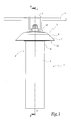
- the anchoring device partially shown in Figure 1 includes a post 1 consisting of a tube 2 surmounted by a post head 3 on which is fixed a cable 4 via a fixed anchor point 5.
- the post 1 is attached to a supporting structure by any suitable means.
- the head of post 3 the general shape of which is that of a mushroom made of metallic material, includes cap 6 circular with flanges 7 of sufficient dimensions to protect against the weather the external walls 8 from the upper end 9 of the tube 2.
- the cap 6 has, on its underside 10 coming in contact with the end 9, a circular skirt 11 in relief, centered on an axis AA '.
- This same face 10 has a truncated cone 12 concentric with the skirt 11 and situated inside the latter.
- the cone 12 and the skirt 11 together define a space annular E.
- This cone 12 is connected to face 10 by its great base. It includes, on its outer wall, several tabs 13. These tabs 13 are trapezoid-shaped rectangle and are fixed by their small base on the wall external of the truncated cone 12. They thus extend radially along the wall of the truncated cone 12 along radial directions with respect to the axis AA '. These tabs 13 extend beyond the small base 12a of the truncated cone 12, so that the angular part tabs 13 is as far as possible from the cone truncated 12, longitudinally and radially.
- the tabs 13 are grouped in pairs, these being regularly spaced on the wall of the cone 12.
- Post head 3 also includes fins 14 and a corner 15.
- the fins 14 are solid elements, planes, of thin and generally trapezoid-shaped.
- the corner 15 is also in the form of a truncated cone.
- a pre-assembled post head 3 includes a styling part 6, fins 14 and a cone 15 connected together by a threaded rod 17.
- This threaded rod 17 is introduced into the post head 3 by the large base of the cone 12 opening onto the upper face 18 of the post head 3.
- the threaded rod 17 passes through the cone 12 and connects it to the corner 15 on which it is blocked by a nut 20.
- the cone 12 and the corner 15 are arranged so that their truncated parts 12 a , 15 a are opposite one another.
- the fins 14 are positioned vertically between these two parts, making their two inclined sides 14 a , 14 b coincide respectively with the frustoconical external walls 12 b and 15 b of the parts 12 and 15.
- the fins 14 have their large bases 14 c facing outwards.
- the post head 3 when the post head 3 is positioned on the end 9, the latter is housed between the ring 11 and the cone 12.
- the free edge 9 a of this end 9 occupies the space E located between the ring 11 and the cone 12.
- a post head comprising at least three fins 14 arranged in a star, allows centering and support homogeneously distributed on the walls of one end tubular 9 circular allowing to fix the head of bollard.
- the shape of the cap 6 is adapted to a tubular end 9 of section cuboid. In this case, use minus four fins 14 arranged in a rectangle or square to ensure effective blocking.
- cap 6 may have a geometric shape different, the same is true for skirt 11.
- the fins 14 have a half-moon shape, in this case, the shape of the external walls of parts 12 and 15 is suitable.
- the fins 14 are held in the same horizontal plane by a holding member, such as an O-ring 19 passing through a groove 16 formed in the large base 14 c of each fin 14.
- a holding member such as an O-ring 19 passing through a groove 16 formed in the large base 14 c of each fin 14.
- the fins 14 can be held in place by grooves and / or tongues arranged on the wall 15b of the frustoconical corner 15.
Landscapes
- Health & Medical Sciences (AREA)
- General Health & Medical Sciences (AREA)
- Business, Economics & Management (AREA)
- Emergency Management (AREA)
- Joining Of Building Structures In Genera (AREA)
- Emergency Lowering Means (AREA)
- Seats For Vehicles (AREA)
- Air Bags (AREA)
- Mutual Connection Of Rods And Tubes (AREA)
- Vehicle Body Suspensions (AREA)
- Fluid-Damping Devices (AREA)
- Piles And Underground Anchors (AREA)
Abstract
Description
- La partie coiffante de la tête de potelet comprend, sur une partie de sa face en contact avec l'extrémité supérieure de l'élément tubulaire du potelet, un logement de réception d'un bord de cette extrémité. Ce logement a des dimensions suffisantes pour coopérer avec des parois d'épaisseurs différentes de l'extrémité supérieure de l'élément tubulaire du potelet.
- La tête de potelet comprend, sur la face en contact avec l'extrémité supérieure de l'élément tubulaire du potelet, un élément tronconique destiné à être inséré dans cette extrémité et un coin creux tronconique se déplaçant en direction de l'élément tronconique sous l'action d'un organe de traction et de blocage.
- Des surfaces externes tronconiques de l'élément et du coin tronconiques coopèrent, respectivement et de manière simultanée, avec des surfaces inclinées complémentaires d'au moins un organe d'appui sur la paroi interne de l'extrémité supérieure de l'élément tubulaire du potelet.
- Au moins un organe d'appui est situé entre l'élément et le coin tronconiques, de sorte que le rapprochement de ces derniers provoque un déplacement radial et centrifuge simultané de cet organe d'appui. L'élément tronconique comprend au moins un moyen de guidage vertical d'au moins un organe d'appui. Ce moyen de guidage comprend une ou plusieurs paires de languettes verticales disposées de part et d'autre de l'organe d'appui.
- La tête de potelet comprend également un organe de traction et de blocage destiné à s'insérer longitudinalement dans l'élément et dans le coin tronconiques pour assurer simultanément leur rapprochement et le déplacement radial de l'organe d'appui.
- L'organe de traction et de blocage assure le maintien d'au moins un organe d'appui en position bloquée contre la paroi interne de l'extrémité supérieure de l'élément tubulaire du potelet.
- la figure 1 est une vue générale d'un potelet d'arrimage d'un point d'ancrage pourvu d'une tête de potelet conforme à l'invention ;
- la figure 2 est une vue en perspective des différents éléments d'une tête de potelet représentée à la figure 1, avant sa mise en place sur l'extrémité supérieure tubulaire d'un tube de potelet ;
- les figures 3 et 4 sont des vues en coupe longitudinale selon le plan de coupe BB' de la figure 1, de l'extrémité supérieure tubulaire de deux potelets de diamètres internes différents, avec la tête de potelet en place ; et
- la figure 5 est une vue analogue à la figure 2 pour un potelet conforme au second mode de réalisation de l'invention.
Claims (11)
- Tête de potelet (3) pour un potelet (1) comprenant un élément tubulaire (2) et assurant l'arrimage d'un point d'ancrage (5) destiné à prévenir les chutes, ladite tête de potelet (3), fixée à l'extrémité supérieure (9) de l'élément tubulaire (2), permettant le maintien d'un ancrage (5) par des moyens de fixation tout en assurant une protection contre la corrosion de l'élément tubulaire (2) en obturant ladite extrémité (9) par une partie coiffante (6), caractérisée en ce que ladite tête de potelet (3) est montée de façon amovible sur ladite extrémité supérieure (9) et comprend un organe de positionnement (11) sur ladite extrémité supérieure (9) situé sur une face (10) de ladite partie coiffante (6) et des moyens (12, 15, 17), situés sur ladite face (10) et assurant, après insertion dans ladite extrémité (9), le blocage de ladite tête de potelet (3) sur ladite extrémité (9) .
- Tête de potelet selon la revendication 1, caractérisée en ce que la partie coiffante (6) comprend sur, une partie de sa face (10) en contact avec l'extrémité supérieure (9) dudit élément tubulaire (2), un logement (E) de réception d'un bord (9a) de ladite extrémité (9).
- Tête de potelet selon la revendication 2, caractérisée en ce que ledit logement (E) a des dimensions suffisantes pour coopérer avec des parois d'épaisseurs différentes (figures 3 et 4) de ladite extrémité (9).
- Tête de potelet selon la revendication 1, caractérisée en ce que ladite tête (3) comprend, sur la face (10) en contact avec ladite extrémité supérieure (9), un élément tronconique (12) destiné à être inséré dans ladite extrémité supérieure (9) et un coin creux (15) tronconique se déplaçant en direction de l'élément tronconique (12), sous l'action d'un organe de traction et de blocage (17).
- Tête de potelet selon la revendication 4, caractérisée en ce que des surfaces externes tronconiques (12b, 15b) de l'élément (12) et du coin (15) tronconiques coopèrent respectivement et de manière simultanée avec des surfaces inclinées complémentaires (14a, 14b) d'au moins un organe d'appui (14) sur la paroi interne de ladite extrémité (9)
- Tête de potelet selon la revendication 4, caractérisée en ce qu'au moins un organe d'appui (14) est situé entre ledit élément (12) et ledit coin (15) tronconiques, de sorte que le rapprochement de ces derniers provoque un déplacement radial et centrifuge simultané dudit organe d'appui (14).
- Tête de potelet selon une des revendications précédentes, caractérisée en ce que ledit élément (12) tronconique comprend au moins un moyen de guidage vertical (13) d'au moins un organe d'appui (14).
- Tête de potelet selon la revendication 7, caractérisée en ce que ledit moyen de guidage comprend au moins une paire de languettes verticales (13) disposées de part et d'autre dudit organe d'appui (14).
- Tête de potelet selon l'une des revendications 4 à 6, ou 7 ou 8 lorsqu'elles dépendent de la revendication 4, caractérisée en ce qu'elle comprend un organe de traction et de blocage (17) destiné à s'insérer longitudinalement dans ledit élément (12) et dans ledit coin (15) tronconiques pour assurer simultanément leur rapprochement et le déplacement radial dudit organe (14).
- Tête de potelet selon la revendication 9, caractérisée en ce que ledit organe de traction et de blocage (17) assure le maintien d'au moins un organe d'appui (14) en position bloquée contre la paroi interne de ladite extrémité (9).
- Equipement de protection destiné à prévenir les chutes en hauteur comprenant au moins un dispositif d'ancrage arrimé à une structure porteuse par au moins un potelet (1) comprenant un élément tubulaire (2) muni d'une tête de potelet (3) résistante à l'arrachement selon l'une quelconque des revendications précédentes.
Applications Claiming Priority (2)
| Application Number | Priority Date | Filing Date | Title |
|---|---|---|---|
| FR0210731 | 2002-08-29 | ||
| FR0210731A FR2843885B1 (fr) | 2002-08-29 | 2002-08-29 | Tete de potelet assurant l'arrimage d'un point d'ancrage destine a prevenir les chutes |
Publications (2)
| Publication Number | Publication Date |
|---|---|
| EP1393777A1 true EP1393777A1 (fr) | 2004-03-03 |
| EP1393777B1 EP1393777B1 (fr) | 2007-02-21 |
Family
ID=31198336
Family Applications (1)
| Application Number | Title | Priority Date | Filing Date |
|---|---|---|---|
| EP03356127A Expired - Lifetime EP1393777B1 (fr) | 2002-08-29 | 2003-08-28 | Tete de potelet |
Country Status (5)
| Country | Link |
|---|---|
| EP (1) | EP1393777B1 (fr) |
| AT (1) | ATE354405T1 (fr) |
| DE (1) | DE60311927T2 (fr) |
| ES (1) | ES2280715T3 (fr) |
| FR (1) | FR2843885B1 (fr) |
Citations (4)
| Publication number | Priority date | Publication date | Assignee | Title |
|---|---|---|---|---|
| FR1315110A (fr) * | 1961-12-04 | 1963-01-18 | Amortisseur de chute | |
| EP0496028A1 (fr) * | 1991-01-22 | 1992-07-29 | Ontario Hydro | Dispositif d'absorption d'énergie pour ligne de sauvetage horizontal dans des systèmes anti-chute |
| FR2755236A1 (fr) * | 1996-10-24 | 1998-04-30 | Henri Joachim Victor Brunet | Capteur d'effort avec alarme radio pour la protection de personnes ou de dispositifs industriels |
| WO1999027213A1 (fr) * | 1997-11-20 | 1999-06-03 | Arvo Poldmaa | Ancrage pour corde de securite |
-
2002
- 2002-08-29 FR FR0210731A patent/FR2843885B1/fr not_active Expired - Fee Related
-
2003
- 2003-08-28 ES ES03356127T patent/ES2280715T3/es not_active Expired - Lifetime
- 2003-08-28 EP EP03356127A patent/EP1393777B1/fr not_active Expired - Lifetime
- 2003-08-28 AT AT03356127T patent/ATE354405T1/de not_active IP Right Cessation
- 2003-08-28 DE DE60311927T patent/DE60311927T2/de not_active Expired - Lifetime
Patent Citations (4)
| Publication number | Priority date | Publication date | Assignee | Title |
|---|---|---|---|---|
| FR1315110A (fr) * | 1961-12-04 | 1963-01-18 | Amortisseur de chute | |
| EP0496028A1 (fr) * | 1991-01-22 | 1992-07-29 | Ontario Hydro | Dispositif d'absorption d'énergie pour ligne de sauvetage horizontal dans des systèmes anti-chute |
| FR2755236A1 (fr) * | 1996-10-24 | 1998-04-30 | Henri Joachim Victor Brunet | Capteur d'effort avec alarme radio pour la protection de personnes ou de dispositifs industriels |
| WO1999027213A1 (fr) * | 1997-11-20 | 1999-06-03 | Arvo Poldmaa | Ancrage pour corde de securite |
Also Published As
| Publication number | Publication date |
|---|---|
| FR2843885B1 (fr) | 2004-10-29 |
| ES2280715T3 (es) | 2007-09-16 |
| DE60311927D1 (de) | 2007-04-05 |
| ATE354405T1 (de) | 2007-03-15 |
| FR2843885A1 (fr) | 2004-03-05 |
| EP1393777B1 (fr) | 2007-02-21 |
| DE60311927T2 (de) | 2007-10-31 |
Similar Documents
| Publication | Publication Date | Title |
|---|---|---|
| FR2493888A1 (fr) | Raccord pour tubes de pieux a enfoncer | |
| EP0956393B1 (fr) | Poteaux et bornes a dispositif de liaison au sol a limite de rupture | |
| EP0913613A1 (fr) | Manchon pour élément de tuyauterie | |
| WO2013104850A1 (fr) | Cuve etanche et isolante munie de moyens de retenue primaires | |
| FR3103233A1 (fr) | Collier de serrage | |
| FR3064976B1 (fr) | Flotteur, notamment d'eolienne offshore. | |
| EP1393777B1 (fr) | Tete de potelet | |
| FR2492938A1 (fr) | Dispositif de fixation d'un couvercle sur un corps, notamment sur un corps de vanne | |
| FR3095215A1 (fr) | Dispositif d’ancrage dans un sol à ailettes et procédé associé | |
| EP1572569B1 (fr) | Dispositif de maintien d'un recipient dans une installation de capsulage | |
| FR2981962A1 (fr) | Sabot de garde-corps a collerette d'etancheite | |
| EP1433501B1 (fr) | Dispositif de fixation d'un potelet d'arrimage à une surface porteuse | |
| FR2829777A1 (fr) | Dispositif d'ancrage au sol d'un objet | |
| BE1012055A3 (fr) | Dispositif de fixation par ecrou. | |
| EP3842597B1 (fr) | Système de connexion articulé pour éléments portants | |
| EP3985209B1 (fr) | Poteau comportant un système anti-soulèvement | |
| FR2627572A1 (fr) | Dispositif d'etancheite pour joint a emboitement entre deux tuyaux | |
| FR2683249A1 (fr) | Piquet pour cloture. | |
| FR2644762A1 (fr) | Convoyeur tubulaire | |
| EP3555486B1 (fr) | Dispositif de protection anti projections pour un moyen de fixation et trappe de visite mettant en oeuvre un tel dispositif | |
| EP2818745A1 (fr) | Bague de roulement | |
| FR2851812A1 (fr) | Dispositif de securisation de raccordement de micro tubes entre eux. | |
| EP2383497B1 (fr) | Dispositif de fixation réglable notamment pour tuyauterie | |
| CA2699492C (fr) | Dispositif de support pour harnais electrique a la traversee d'une structure | |
| EP4709947A1 (fr) | Dispositif et procédé de raccordement d'un mât d'éolienne à une embase |
Legal Events
| Date | Code | Title | Description |
|---|---|---|---|
| PUAI | Public reference made under article 153(3) epc to a published international application that has entered the european phase |
Free format text: ORIGINAL CODE: 0009012 |
|
| AK | Designated contracting states |
Kind code of ref document: A1 Designated state(s): AT BE BG CH CY CZ DE DK EE ES FI FR GB GR HU IE IT LI LU MC NL PT RO SE SI SK TR |
|
| AX | Request for extension of the european patent |
Extension state: AL LT LV MK |
|
| 17P | Request for examination filed |
Effective date: 20040410 |
|
| AKX | Designation fees paid |
Designated state(s): AT BE BG CH CY CZ DE DK EE ES FI FR GB GR HU IE IT LI LU MC NL PT RO SE SI SK TR |
|
| GRAP | Despatch of communication of intention to grant a patent |
Free format text: ORIGINAL CODE: EPIDOSNIGR1 |
|
| GRAS | Grant fee paid |
Free format text: ORIGINAL CODE: EPIDOSNIGR3 |
|
| GRAA | (expected) grant |
Free format text: ORIGINAL CODE: 0009210 |
|
| AK | Designated contracting states |
Kind code of ref document: B1 Designated state(s): AT BE BG CH CY CZ DE DK EE ES FI FR GB GR HU IE IT LI LU MC NL PT RO SE SI SK TR |
|
| PG25 | Lapsed in a contracting state [announced via postgrant information from national office to epo] |
Ref country code: DK Free format text: LAPSE BECAUSE OF FAILURE TO SUBMIT A TRANSLATION OF THE DESCRIPTION OR TO PAY THE FEE WITHIN THE PRESCRIBED TIME-LIMIT Effective date: 20070221 Ref country code: FI Free format text: LAPSE BECAUSE OF FAILURE TO SUBMIT A TRANSLATION OF THE DESCRIPTION OR TO PAY THE FEE WITHIN THE PRESCRIBED TIME-LIMIT Effective date: 20070221 Ref country code: SI Free format text: LAPSE BECAUSE OF FAILURE TO SUBMIT A TRANSLATION OF THE DESCRIPTION OR TO PAY THE FEE WITHIN THE PRESCRIBED TIME-LIMIT Effective date: 20070221 Ref country code: IE Free format text: LAPSE BECAUSE OF FAILURE TO SUBMIT A TRANSLATION OF THE DESCRIPTION OR TO PAY THE FEE WITHIN THE PRESCRIBED TIME-LIMIT Effective date: 20070221 Ref country code: NL Free format text: LAPSE BECAUSE OF FAILURE TO SUBMIT A TRANSLATION OF THE DESCRIPTION OR TO PAY THE FEE WITHIN THE PRESCRIBED TIME-LIMIT Effective date: 20070221 Ref country code: AT Free format text: LAPSE BECAUSE OF FAILURE TO SUBMIT A TRANSLATION OF THE DESCRIPTION OR TO PAY THE FEE WITHIN THE PRESCRIBED TIME-LIMIT Effective date: 20070221 |
|
| REG | Reference to a national code |
Ref country code: GB Ref legal event code: FG4D Free format text: NOT ENGLISH |
|
| REG | Reference to a national code |
Ref country code: CH Ref legal event code: EP |
|
| REF | Corresponds to: |
Ref document number: 60311927 Country of ref document: DE Date of ref document: 20070405 Kind code of ref document: P |
|
| REG | Reference to a national code |
Ref country code: IE Ref legal event code: FG4D Free format text: LANGUAGE OF EP DOCUMENT: FRENCH |
|
| GBT | Gb: translation of ep patent filed (gb section 77(6)(a)/1977) |
Effective date: 20070404 |
|
| PG25 | Lapsed in a contracting state [announced via postgrant information from national office to epo] |
Ref country code: SE Free format text: LAPSE BECAUSE OF FAILURE TO SUBMIT A TRANSLATION OF THE DESCRIPTION OR TO PAY THE FEE WITHIN THE PRESCRIBED TIME-LIMIT Effective date: 20070521 |
|
| PG25 | Lapsed in a contracting state [announced via postgrant information from national office to epo] |
Ref country code: BG Free format text: LAPSE BECAUSE OF EXPIRATION OF PROTECTION Effective date: 20070522 |
|
| PG25 | Lapsed in a contracting state [announced via postgrant information from national office to epo] |
Ref country code: PT Free format text: LAPSE BECAUSE OF FAILURE TO SUBMIT A TRANSLATION OF THE DESCRIPTION OR TO PAY THE FEE WITHIN THE PRESCRIBED TIME-LIMIT Effective date: 20070723 |
|
| NLV1 | Nl: lapsed or annulled due to failure to fulfill the requirements of art. 29p and 29m of the patents act | ||
| REG | Reference to a national code |
Ref country code: ES Ref legal event code: FG2A Ref document number: 2280715 Country of ref document: ES Kind code of ref document: T3 |
|
| REG | Reference to a national code |
Ref country code: IE Ref legal event code: FD4D |
|
| PG25 | Lapsed in a contracting state [announced via postgrant information from national office to epo] |
Ref country code: SK Free format text: LAPSE BECAUSE OF FAILURE TO SUBMIT A TRANSLATION OF THE DESCRIPTION OR TO PAY THE FEE WITHIN THE PRESCRIBED TIME-LIMIT Effective date: 20070221 |
|
| PLBE | No opposition filed within time limit |
Free format text: ORIGINAL CODE: 0009261 |
|
| STAA | Information on the status of an ep patent application or granted ep patent |
Free format text: STATUS: NO OPPOSITION FILED WITHIN TIME LIMIT |
|
| PG25 | Lapsed in a contracting state [announced via postgrant information from national office to epo] |
Ref country code: RO Free format text: LAPSE BECAUSE OF FAILURE TO SUBMIT A TRANSLATION OF THE DESCRIPTION OR TO PAY THE FEE WITHIN THE PRESCRIBED TIME-LIMIT Effective date: 20070221 Ref country code: CZ Free format text: LAPSE BECAUSE OF FAILURE TO SUBMIT A TRANSLATION OF THE DESCRIPTION OR TO PAY THE FEE WITHIN THE PRESCRIBED TIME-LIMIT Effective date: 20070221 |
|
| 26N | No opposition filed |
Effective date: 20071122 |
|
| REG | Reference to a national code |
Ref country code: CH Ref legal event code: PL |
|
| PG25 | Lapsed in a contracting state [announced via postgrant information from national office to epo] |
Ref country code: MC Free format text: LAPSE BECAUSE OF NON-PAYMENT OF DUE FEES Effective date: 20070831 Ref country code: LI Free format text: LAPSE BECAUSE OF NON-PAYMENT OF DUE FEES Effective date: 20070831 Ref country code: CH Free format text: LAPSE BECAUSE OF NON-PAYMENT OF DUE FEES Effective date: 20070831 Ref country code: GR Free format text: LAPSE BECAUSE OF FAILURE TO SUBMIT A TRANSLATION OF THE DESCRIPTION OR TO PAY THE FEE WITHIN THE PRESCRIBED TIME-LIMIT Effective date: 20070522 |
|
| PG25 | Lapsed in a contracting state [announced via postgrant information from national office to epo] |
Ref country code: EE Free format text: LAPSE BECAUSE OF FAILURE TO SUBMIT A TRANSLATION OF THE DESCRIPTION OR TO PAY THE FEE WITHIN THE PRESCRIBED TIME-LIMIT Effective date: 20070221 |
|
| PG25 | Lapsed in a contracting state [announced via postgrant information from national office to epo] |
Ref country code: CY Free format text: LAPSE BECAUSE OF FAILURE TO SUBMIT A TRANSLATION OF THE DESCRIPTION OR TO PAY THE FEE WITHIN THE PRESCRIBED TIME-LIMIT Effective date: 20070221 |
|
| PG25 | Lapsed in a contracting state [announced via postgrant information from national office to epo] |
Ref country code: LU Free format text: LAPSE BECAUSE OF NON-PAYMENT OF DUE FEES Effective date: 20070828 |
|
| PG25 | Lapsed in a contracting state [announced via postgrant information from national office to epo] |
Ref country code: TR Free format text: LAPSE BECAUSE OF FAILURE TO SUBMIT A TRANSLATION OF THE DESCRIPTION OR TO PAY THE FEE WITHIN THE PRESCRIBED TIME-LIMIT Effective date: 20070221 Ref country code: HU Free format text: LAPSE BECAUSE OF FAILURE TO SUBMIT A TRANSLATION OF THE DESCRIPTION OR TO PAY THE FEE WITHIN THE PRESCRIBED TIME-LIMIT Effective date: 20070822 |
|
| PGFP | Annual fee paid to national office [announced via postgrant information from national office to epo] |
Ref country code: BE Payment date: 20110826 Year of fee payment: 9 |
|
| BERE | Be: lapsed |
Owner name: GAMESYSTEM Effective date: 20120831 |
|
| PG25 | Lapsed in a contracting state [announced via postgrant information from national office to epo] |
Ref country code: BE Free format text: LAPSE BECAUSE OF NON-PAYMENT OF DUE FEES Effective date: 20120831 |
|
| PGFP | Annual fee paid to national office [announced via postgrant information from national office to epo] |
Ref country code: ES Payment date: 20130828 Year of fee payment: 11 Ref country code: DE Payment date: 20130812 Year of fee payment: 11 |
|
| PGFP | Annual fee paid to national office [announced via postgrant information from national office to epo] |
Ref country code: GB Payment date: 20130816 Year of fee payment: 11 |
|
| PGFP | Annual fee paid to national office [announced via postgrant information from national office to epo] |
Ref country code: IT Payment date: 20130808 Year of fee payment: 11 |
|
| PGFP | Annual fee paid to national office [announced via postgrant information from national office to epo] |
Ref country code: FR Payment date: 20140717 Year of fee payment: 12 |
|
| REG | Reference to a national code |
Ref country code: DE Ref legal event code: R119 Ref document number: 60311927 Country of ref document: DE |
|
| GBPC | Gb: european patent ceased through non-payment of renewal fee |
Effective date: 20140828 |
|
| PG25 | Lapsed in a contracting state [announced via postgrant information from national office to epo] |
Ref country code: IT Free format text: LAPSE BECAUSE OF NON-PAYMENT OF DUE FEES Effective date: 20140828 |
|
| REG | Reference to a national code |
Ref country code: DE Ref legal event code: R119 Ref document number: 60311927 Country of ref document: DE Effective date: 20150303 |
|
| PG25 | Lapsed in a contracting state [announced via postgrant information from national office to epo] |
Ref country code: DE Free format text: LAPSE BECAUSE OF NON-PAYMENT OF DUE FEES Effective date: 20150303 Ref country code: GB Free format text: LAPSE BECAUSE OF NON-PAYMENT OF DUE FEES Effective date: 20140828 |
|
| REG | Reference to a national code |
Ref country code: ES Ref legal event code: FD2A Effective date: 20150928 |
|
| PG25 | Lapsed in a contracting state [announced via postgrant information from national office to epo] |
Ref country code: ES Free format text: LAPSE BECAUSE OF NON-PAYMENT OF DUE FEES Effective date: 20140829 |
|
| REG | Reference to a national code |
Ref country code: FR Ref legal event code: ST Effective date: 20160429 |
|
| PG25 | Lapsed in a contracting state [announced via postgrant information from national office to epo] |
Ref country code: FR Free format text: LAPSE BECAUSE OF NON-PAYMENT OF DUE FEES Effective date: 20150831 |