EP1393797B1 - Appareil pour agiter et pour mélanger - Google Patents
Appareil pour agiter et pour mélanger Download PDFInfo
- Publication number
- EP1393797B1 EP1393797B1 EP03017719A EP03017719A EP1393797B1 EP 1393797 B1 EP1393797 B1 EP 1393797B1 EP 03017719 A EP03017719 A EP 03017719A EP 03017719 A EP03017719 A EP 03017719A EP 1393797 B1 EP1393797 B1 EP 1393797B1
- Authority
- EP
- European Patent Office
- Prior art keywords
- shaking
- vessel holder
- vessels
- mixing apparatus
- eccentric
- Prior art date
- Legal status (The legal status is an assumption and is not a legal conclusion. Google has not performed a legal analysis and makes no representation as to the accuracy of the status listed.)
- Expired - Lifetime
Links
Images





Classifications
-
- G—PHYSICS
- G01—MEASURING; TESTING
- G01N—INVESTIGATING OR ANALYSING MATERIALS BY DETERMINING THEIR CHEMICAL OR PHYSICAL PROPERTIES
- G01N1/00—Sampling; Preparing specimens for investigation
- G01N1/28—Preparing specimens for investigation including physical details of (bio-)chemical methods covered elsewhere, e.g. G01N33/50, C12Q
- G01N1/38—Diluting, dispersing or mixing samples
-
- B—PERFORMING OPERATIONS; TRANSPORTING
- B01—PHYSICAL OR CHEMICAL PROCESSES OR APPARATUS IN GENERAL
- B01F—MIXING, e.g. DISSOLVING, EMULSIFYING OR DISPERSING
- B01F29/00—Mixers with rotating receptacles
- B01F29/30—Mixing the contents of individual packages or containers, e.g. by rotating tins or bottles
- B01F29/32—Containers specially adapted for coupling to rotating frames or the like; Coupling means therefor
- B01F29/322—Containers specially adapted for coupling to rotating frames or the like; Coupling means therefor of two or more containers supported for simultaneous mixing, e.g. for bottles in crates
-
- B—PERFORMING OPERATIONS; TRANSPORTING
- B01—PHYSICAL OR CHEMICAL PROCESSES OR APPARATUS IN GENERAL
- B01F—MIXING, e.g. DISSOLVING, EMULSIFYING OR DISPERSING
- B01F31/00—Mixers with shaking, oscillating, or vibrating mechanisms
- B01F31/20—Mixing the contents of independent containers, e.g. test tubes
- B01F31/201—Holders therefor
-
- B—PERFORMING OPERATIONS; TRANSPORTING
- B01—PHYSICAL OR CHEMICAL PROCESSES OR APPARATUS IN GENERAL
- B01F—MIXING, e.g. DISSOLVING, EMULSIFYING OR DISPERSING
- B01F31/00—Mixers with shaking, oscillating, or vibrating mechanisms
- B01F31/20—Mixing the contents of independent containers, e.g. test tubes
- B01F31/265—Mixing the contents of independent containers, e.g. test tubes the vibrations being caused by an unbalanced rotating member
-
- B—PERFORMING OPERATIONS; TRANSPORTING
- B01—PHYSICAL OR CHEMICAL PROCESSES OR APPARATUS IN GENERAL
- B01F—MIXING, e.g. DISSOLVING, EMULSIFYING OR DISPERSING
- B01F35/00—Accessories for mixers; Auxiliary operations or auxiliary devices; Parts or details of general application
- B01F35/90—Heating or cooling systems
- B01F35/92—Heating or cooling systems for heating the outside of the receptacle, e.g. heated jackets or burners
-
- B—PERFORMING OPERATIONS; TRANSPORTING
- B01—PHYSICAL OR CHEMICAL PROCESSES OR APPARATUS IN GENERAL
- B01F—MIXING, e.g. DISSOLVING, EMULSIFYING OR DISPERSING
- B01F2101/00—Mixing characterised by the nature of the mixed materials or by the application field
- B01F2101/23—Mixing of laboratory samples e.g. in preparation of analysing or testing properties of materials
-
- B—PERFORMING OPERATIONS; TRANSPORTING
- B01—PHYSICAL OR CHEMICAL PROCESSES OR APPARATUS IN GENERAL
- B01F—MIXING, e.g. DISSOLVING, EMULSIFYING OR DISPERSING
- B01F2215/00—Auxiliary or complementary information in relation with mixing
- B01F2215/04—Technical information in relation with mixing
- B01F2215/0413—Numerical information
- B01F2215/0418—Geometrical information
- B01F2215/0427—Numerical distance values, e.g. separation, position
-
- B—PERFORMING OPERATIONS; TRANSPORTING
- B01—PHYSICAL OR CHEMICAL PROCESSES OR APPARATUS IN GENERAL
- B01F—MIXING, e.g. DISSOLVING, EMULSIFYING OR DISPERSING
- B01F2215/00—Auxiliary or complementary information in relation with mixing
- B01F2215/04—Technical information in relation with mixing
- B01F2215/0413—Numerical information
- B01F2215/0418—Geometrical information
- B01F2215/0431—Numerical size values, e.g. diameter of a hole or conduit, area, volume, length, width, or ratios thereof
-
- G—PHYSICS
- G01—MEASURING; TESTING
- G01N—INVESTIGATING OR ANALYSING MATERIALS BY DETERMINING THEIR CHEMICAL OR PHYSICAL PROPERTIES
- G01N35/00—Automatic analysis not limited to methods or materials provided for in any single one of groups G01N1/00 - G01N33/00; Handling materials therefor
- G01N2035/00465—Separating and mixing arrangements
- G01N2035/00524—Mixing by agitating sample carrier
Definitions
- the invention relates to a shaking and mixing device with an electric drive, an eccentric unit driven by the drive and a vessel holder moved by the eccentric unit and designed to receive the vessels to be moved by the shaker and mixer.
- Such shakers and mixers are known in many embodiments in the art. They are used for shaking and mixing samples, which are present in small but also large vessels, in various fields such as environmental engineering, biology, biochemistry, medical diagnostics, microbiology, cell biology, etc.
- the vessels filled with the sample to be shaken or mixed may be many vessels suitable for the particular application, for example test tubes, flasks, Erlenmeyer flasks, dishes, petri dishes, racks, separatory funnels, microtiter plates, bottles, tubes or other vessels. Also, the double or multi-level arrangement of vessels when shaking or mixing is in use.
- a shaking and mixing device in which a vessel holder with an articulated mounted on a drive shaft eccentric is spatially moved in three dimensions and thereby performs vertical up and down movements in addition to a rotational movement.
- a vibrating table driven by an eccentric unit is known, on which vessels with samples to be mixed can be placed.
- suitable vessel holders and any attachments or adapters are used.
- suitable vessel holders and any attachments or adapters are used.
- special training courses such as test tube shakers or platform shakers.
- the shaking and mixing movement can be configured in many ways. One distinguishes, for example, one-, two- and three-dimensional movements as well as vibrating, circular, rotating, reciprocal, overhead, rocking and transversal movements.
- the shakers and mixers usually have an adjustable speed or shaking frequency and a fixed or adjustable orbit, i. a fixed or adjustable amplitude of the movement unit.
- adjusting amplitude of the shaken material or the moving vessels may differ by resonance phenomena and elastic or movable brackets thereof.
- the shaking and mixing apparatus are constructed so that vessel holders are mounted on a shaking table, which is driven by an eccentric unit, which receive vessels in which the sample to be shaken is located.
- a shaking table which is driven by an eccentric unit, which receive vessels in which the sample to be shaken is located.
- an eccentric unit which receive vessels in which the sample to be shaken is located.
- the invention is based on this prior art, the task of creating a shaker and mixing device of the type described above, especially for slim vessels, which less wobbles and trembles and in which the vessels wobble less, a more precise Shake and do not fall out of the vessel holder due to shaking and shaking.
- a shaking and mixing apparatus has the further advantages that it operates with a smaller balancing mass in the eccentric unit, with larger and heavier samples and vessels, with a larger shaking frequency and with a larger orbit than a shaking and mixing apparatus according to the prior art can be.
- the center of gravity of the vessel holder and vessels below the oriented in the eccentric plane in which the uppermost point of the eccentric unit is located or that the center of gravity of the vessel holder and vessels above the oriented in the eccentric plane , in which the lowest point of the eccentric unit is located.
- the plane of the center of gravity of the vessel holder and vessels and the plane of the center of gravity of the eccentric unit be substantially coincident.
- a precise mathematical match will hardly be achievable in practice, since the position of the center of gravity of the vessel holder and vessels is changed by different vessels or by different filling of the vessels with samples.
- the aim is to minimize the vertical distance between the centers of gravity.
- the lateral distance of the centers of gravity is as low as possible.
- the construction of the shaking and mixing device with vessel holder and vessels can be designed so that the height and / or side distance, which should be as small as possible according to the invention, based on empty, inserted into the vessel holder vessels.
- the height and / or side distance be related to vessels inserted into the vessel holder which are filled with a typical amount of a typical shaker or Mixed goods are filled.
- Fig. 1 shows a section through a typical shaking and mixing device according to the prior art. It comprises a housing 1 with operating and adjusting elements 2 and an electric drive, for example a magnet driven by an electric rotary field or a drive motor 3, which drives an eccentric unit 4 with a balancing mass 5.
- the eccentric unit 4 has a shaking table 6, on which the vessels 8 to be moved are arranged by means of a vessel holder 7.
- Shaking funnel is understood to mean the depression, which is also referred to as a thrombus, which forms when shaking a liquid sample in the region of its central vertical axis.
- the shaking frequency and the shaking amplitude, i. orbit or vibration is counteracted with a large mass of equipment.
- the vessels 8 can also fall out of the vessel holder 7 upwards.
- a plane of the eccentric movement is understood to mean a movement perpendicular to the axis of rotation 12 of the eccentric unit 4, ie a plane in which the balancing mass 5 rotates and which is parallel to the plane in which the vessel holder 7 and the vessels 8 are moved.
- Fig. 2 shows a corresponding embodiment of a shaking and mixing device 13 according to the invention, in which the vessel holder 7 is formed with the vessels 8 such that the height distance h from the common center of gravity 11 of the vessel holder and vessels to the center of gravity 10 of the eccentric unit as low as possible and these two priorities 10, 11 are essentially coincidental.
- a remaining small height distance h is shown for illustration purposes.
- the center of gravity 11 of the vessel holder 7 and the filled vessels 8 is within the eccentric unit (height H) and not above it as in Fig. 1 according to the prior art.
- the vessel holder 7 and the vessels 8 are not arranged above the eccentric unit 4, but rather around the eccentric unit 4 as it were. It may be found in preferred embodiments that the center of gravity 11 of the vessel holder 7 and vessels 8 below the oriented in the eccentric motion plane in which the uppermost point 14 of the eccentric unit 4 is located, and that the center of gravity 11 of vessel holder 7 and vessels 8 above the oriented in the eccentric movement plane, in which the lowest point 15 of the eccentric unit 4 is located. In order to achieve the smallest possible height distance h, can also be provided according to an advantageous feature that the lowest point 16 of the vessels 8 below the oriented in the eccentric plane, in which the lowest point 15 of the eccentric unit 4 is located.
- the height distance h is preferably zero. According to an advantageous feature it is therefore proposed that the height distance h between the plane of the center of gravity 11 of the vessel holder 7 and vessels 8 and the plane of the center of gravity 10 of the eccentric unit 4 is smaller than the height H of the eccentric unit 4, measured perpendicular to the plane of the eccentric movement, preferably less than 50%, preferably less than 25% and particularly preferably less than 10% of the height H is.
- the aim is, as already explained, the smallest possible vertical distance h, that is, that the plane of the center of gravity 11 of the vessel holder 7 and vessels 8 and the plane of the center of gravity 10 of the eccentric unit 4 substantially coincide.
- the overall height H of the eccentric unit 4 extends from its uppermost point 14 to its lowest point 15.
- a shaking and mixing device 13 In a shaking and mixing device 13 according to the invention, one will also endeavor to arrange the center of gravity 9 of the device, the center of gravity 10 of the eccentric unit 4 and the center of gravity 11 of the vessel holder 7 and vessels 8 aligned one above the other. According to further advantageous features, it is therefore proposed that the common Center of gravity 11 of vessel holder 7 and vessels 8 in only a small lateral distance, measured in the plane of the eccentric motion, to the axis of rotation 12 of the eccentric unit 4 or that the side distance is smaller than the height H of the eccentric unit 4, measured perpendicular to the plane of the eccentric movement, preferably less than 25%, preferably less than 10% and particularly preferably less than 5% of the height H is. In general, it will be advantageous if the common center of gravity 11 of the vessel holder 7 and vessels 8 lies substantially on the axis of rotation of the eccentric unit 4.
- FIG. 3 shows a detailed illustration of the eccentric unit 4 with the vessel holder 7 and the vessels 8 inserted therein.
- the drive motor 3 is shown broken off at the bottom. Its rotor 17 drives a motor shaft 18 which moves the eccentric unit 4 in motion.
- the eccentric unit 4 comprises an eccentric 19, ball bearings 20, a slotted disc 21 for speed detection and the balancing mass 5.
- the eccentric unit 4 has a hub 22 which forms the receptacle for the vessel holder 7 placed thereon.
- an elastic element for example a rubber element 23, be provided to prevent rotation of the vessel holder 7.
- the vessel holder 7 has receiving openings or other fastening elements for receiving or securing the vessels 8.
- the vessel holder 7 is arranged around the eccentric unit 4 around. This also applies to the carried by the vessel holder 7 vessels 8, which protrude in the illustrated embodiment, both upwards and downwards over the eccentric 4, so that their focus or the common center of gravity 11 of vessel holder 7 and 8 vessels as small as possible Height distance h to the center of gravity 10 of the eccentric unit 4 has. So that the vessels 8 can project downwards beyond the eccentric unit 4, the housing 1 has corresponding recesses 24 (see FIG. 2).
- FIG. 4 shows a modification of the shaking and mixing device 13 is shown in FIG. 2, in which to better compensate for any remaining vibrations of the electric drive with eccentric 4 and vessel holder 7 by means of an elastic suspension 25 to the housing 1 of the device or a heavy Base plate 26 of the device 13 is connected.
- the vessel holder 7 may be designed so that vessels 8 of any shape can be accommodated.
- the vessel holder may be made of any material, such as an elastomer, a plastic or metal, and may be both rigid and have inherent flexibility.
- the vessels 8 are advantageously arranged on one or more circles lying on the vessel holder 7, but it can also be any other placements, for example in a rectangle or a rectangular grid, made.
- vessels are shown as vessels.
- vessel holders 7 for other vessel shapes are partially explained.
- the vessel holders 7 can be interchangeably arranged on the eccentric unit 4, so that a quick replacement for the particular application is made possible.
- the vessel holder 7 has replaceable support elements for attaching vessels 8 to the vessel holder 7.
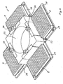
- FIG. 5 shows an exemplary embodiment of a vessel holder 7 for vessels 8, which are Erlenmeyer flasks or similar vessels. It comprises a rectangular attachment 27 with the hub 22, which is placed on the hub 22 of the eccentric unit 4.
- the attachment 27 is provided with support plates 28 which form the support elements for the vessels 8.
- the vessels 8 are held with retaining clips 29 on the support plates 28, and the support plates 28 are fastened by means of fastening screws 30 replaceable on the attachment 27.
- the support plates 28 are arranged below the upper edge of the attachment 27, so that the common center of gravity of the vessel holder 7 and vessels 8 is deep and possibly with the center of gravity of the eccentric unit 4, on which the attachment 27 is placed, coincides.
- FIG. 6 shows a vessel holder 7 for vessels 8, which are microtiter plates. These are fastened with retaining clips 29 on support plates 28. Otherwise, the design of the vessel holder 7 of FIG. 6 largely corresponds to that of FIG. 5.
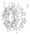
- FIG. 7 shows, in a modification to FIG. 5, a further vessel holder 7 according to the invention, which contains test tube blocks 31 for holding test tubes.
- the test tube blocks 31 are provided with receiving bores 32, into which the test tubes are inserted.
- the remaining structure corresponds to that of the vessel holder 7 of FIG. 5.
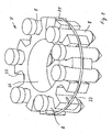
- FIG. 8 shows a ring-shaped vessel holder 7 with receiving bores 32 for reaction vessels and small test tubes. These vessel holder is connected to a hub 22 on a corresponding receiving shoulder of the Eccentric unit 4 placed so that the vessels 8 are arranged around the eccentric unit 4 around.
- FIG. 9 and 10 illustrate preferred embodiments of a vessel holder 7 for vessels 8 in the form of tubes or test tubes.
- FIG. 9 shows an embodiment for vessels 8 having a larger diameter, for example greater than 20 mm
- FIG. 10 shows a corresponding vessel holder 7 for vessels 8 having a smaller diameter, for example less than 20 mm.
- the peculiarity of the vessel holder 7 shown in Figures 9 and 10 is that it has groove-shaped, perpendicular to the eccentric movement receiving slots 33 which are arranged along the circumference of the vessel holder 7.
- the vessels 8 are inserted into the receiving slots 33 and clamped. If necessary, it may be provided that the vessel holder 7 has an elastic, along the circumference of the vessel holder 7 extending retaining element 34, for example in the form of a rubber-elastic tether or a coil spring, for clamping the vessels 8 in the receiving slots 33.
- a particular advantage of the embodiment shown in Figures 9 and 10 is that during shaking and mixing the samples contained in the vessels 8 are visible. This makes it possible to reduce the mixing effect, i. to check the formation of a mixing funnel in the sample, or to control a running in the vessels 8 reaction.
- FIGS. 11 to 13, in a modification to FIG. 10, show a vessel holder 7 with a heater 35 in the form of a heating band and temperature sensors 36 for regulating the heating power.
- the vessel holder 7 shown in Figures 14 to 16 is additionally formed with a cooling device 37 in the form of a cooling channel.
- the optionally to be used holding elements 34 of FIG. 10 are not shown for clarity.
Landscapes
- Chemical & Material Sciences (AREA)
- Chemical Kinetics & Catalysis (AREA)
- Physics & Mathematics (AREA)
- Health & Medical Sciences (AREA)
- Life Sciences & Earth Sciences (AREA)
- Analytical Chemistry (AREA)
- Biochemistry (AREA)
- General Health & Medical Sciences (AREA)
- General Physics & Mathematics (AREA)
- Immunology (AREA)
- Pathology (AREA)
- Mixers With Rotating Receptacles And Mixers With Vibration Mechanisms (AREA)
- Sampling And Sample Adjustment (AREA)
- Automatic Analysis And Handling Materials Therefor (AREA)
Claims (21)
- Appareil pour agiter et mélanger (13) comportant un entraînement électrique (3), une unité d'excentrique (4) entraînée par l'entraînement (3) et un support de récipients (7) mis en mouvement par l'unité d'excentrique (4), qui est configuré pour recevoir les récipients (8) devant être mis en mouvement par l'appareil pour agiter et mélanger (13)
dans lequel le centre de gravité (11) commun du support de récipients (7) et des récipients (8) se situe à l'intérieur de l'unité d'excentrique (4) et
dans lequel le support de récipients (7) en service exécute un mouvement circulaire dans un plan orienté parallèlement au mouvement excentrique de sorte qu'il existe un vortex d'agitation dans les échantillons liquides dans les récipients (8) reçus dans le support de récipients (7). - Appareil pour agiter et mélanger selon la revendication 1, caractérisé en ce que les récipients (8) et le support de récipients (7) sont disposés autour de l'unité d'excentrique (4).
- Appareil pour agiter et mélanger (13) selon l'une des revendications précédentes, caractérisé en ce que le centre de gravité (11) du support de récipients (7) et des récipients (8) est disposé en dessous du plan orienté dans le mouvement excentrique dans lequel se situe le point le plus haut (14) de l'unité d'excentrique (4) .
- Appareil pour agiter et mélanger (13) selon l'une des revendications précédentes, caractérisé en ce que le centre de gravité (11) du support de récipients (7) et des récipients (8) est disposé au-dessus du plan orienté dans le mouvement excentrique dans lequel se situe le point le plus bas (15) de l'unité d'excentrique (4) .
- Appareil pour agiter et mélanger (13) selon l'une des revendications précédentes, caractérisé en ce que le point le plus bas (16) des récipients (8) est disposé en dessous du plan orienté dans le mouvement excentrique dans lequel se situe le point le plus bas (15) de l'unité d'excentrique (4).
- Appareil pour agiter et mélanger (13) selon l'une des revendications précédentes, caractérisé en ce que l'écartement en hauteur (h) entre le plan du centre de gravité (11) du support de récipients (7) et les récipients (8) et le plan du centre de gravité (10) de l'unité d'excentrique (4) est inférieur à la hauteur de construction (H) de l'unité d'excentrique (4), mesuré perpendiculairement au plan du mouvement excentrique, de préférence inférieur à 50 %, de manière préférée inférieur à 25 % et de manière particulièrement préférée inférieur à 10 % de la hauteur de construction (H).
- Appareil pour agiter et mélanger (13) selon l'une des revendications précédentes, caractérisé en ce que le plan du centre de gravité (11) du support de récipients (7) et des récipients (8) et le plan du centre de gravité (10) de l'unité d'excentrique (4) coïncident sensiblement.
- Appareil pour agiter et mélanger (13) selon l'une des revendications précédentes, caractérisé en ce que le centre de gravité (11) commun du support de récipients (7) et des récipients (8) se situe à une distance latérale, mesurée dans le plan du mouvement excentrique, seulement minime de l'axe de rotation (12) de l'unité d'excentrique (4).
- Appareil pour agiter et mélanger (13) selon la revendication 8, caractérisé en ce que l'écartement latéral est inférieur à la hauteur de construction (H) de l'unité d'excentrique (4), mesurée perpendiculairement au plan du mouvement excentrique, de préférence inférieur à 25 %, de manière préférée inférieur à 10 % et de manière particulièrement préférée inférieur à 5 % de la hauteur de construction (H).
- Appareil pour agiter et mélanger (13) selon la revendication 8, caractérisé en ce que le centre de gravité (11) commun du support de récipients (7) et des récipients (8) se situe sensiblement sur l'axe de rotation (12) de l'unité d'excentrique (4).
- Appareil pour agiter et mélanger (13) selon l'une des revendications précédentes, caractérisé en ce que l'écartement en hauteur et/ou latéral, qui selon l'invention doit être aussi minime que possible, se rapporte à des récipients (8) vides placés dans le support de récipients (7).
- Appareil pour agiter et mélanger (13) selon l'une des revendications précédentes, caractérisé en ce que l'écartement en hauteur et/ou latéral se rapporte aux récipients (8) insérés dans le support de récipients (7), qui sont remplis d'une quantité typique d'un produit à agiter ou à mélanger typique.
- Appareil pour agiter et mélanger (13) selon l'une des revendications précédentes, caractérisé en ce que l'entraînement électrique (3) avec l'unité d'excentrique (4) et le support de récipients (7) sont reliés au moyen d'une suspension élastique (25) au boîtier (1) de l'appareil (13) ou à une plaque de base (26) de l'appareil (13).
- Appareil pour agiter et mélanger (13) selon l'une des revendications précédentes, caractérisé en ce que les récipients (8) sont disposés sur le support de récipients (7) sur un ou plusieurs cercles.
- Appareil pour agiter et mélanger (13) selon l'une des revendications précédentes, caractérisé en ce que support de récipients (7) est disposé de manière échangeable sur l'unité d'excentrique (4).
- Appareil pour agiter et mélanger (13) selon l'une des revendications précédentes, caractérisé en ce que le support de récipients (7) présente des éléments de support échangeables pour fixer des récipients (8) au support de récipients (7).
- Appareil pour agiter et mélanger (13) selon l'une des revendications précédentes, caractérisé en ce que support de récipients (7) est configuré de manière annulaire.
- Appareil pour agiter et mélanger (13) selon l'une des revendications précédentes, caractérisé en ce que le support de récipients (7) présente des fentes réceptrices (33) en forme de rainures, s'étendant perpendiculairement au mouvement excentrique, qui sont disposées le long du pourtour du support de récipients ()7.
- Appareil pour agiter et mélanger (13) selon la revendication 18, caractérisé en ce que le support de récipients (7) comporte un élément de maintien élastique (34), s'étendant sur le pourtour du support de récipients (7), pour serrer les récipients (9) dans les fentes réceptrices (33).
- Appareil pour agiter et mélanger (13) selon l'une des revendications précédentes, caractérisé en ce qu'il comporte un dispositif de chauffage (35) pour chauffer le support de récipients (7).
- Appareil pour agiter et mélanger (13) selon l'une des revendications précédentes, caractérisé en ce qu'il comporte un dispositif de refroidissement (37) pour refroidir le support de récipients (7).
Applications Claiming Priority (2)
| Application Number | Priority Date | Filing Date | Title |
|---|---|---|---|
| DE10239786A DE10239786A1 (de) | 2002-08-29 | 2002-08-29 | Schüttel- und Mischgerät |
| DE10239786 | 2002-08-29 |
Publications (3)
| Publication Number | Publication Date |
|---|---|
| EP1393797A2 EP1393797A2 (fr) | 2004-03-03 |
| EP1393797A3 EP1393797A3 (fr) | 2004-05-26 |
| EP1393797B1 true EP1393797B1 (fr) | 2006-07-12 |
Family
ID=31197492
Family Applications (1)
| Application Number | Title | Priority Date | Filing Date |
|---|---|---|---|
| EP03017719A Expired - Lifetime EP1393797B1 (fr) | 2002-08-29 | 2003-08-02 | Appareil pour agiter et pour mélanger |
Country Status (3)
| Country | Link |
|---|---|
| EP (1) | EP1393797B1 (fr) |
| AT (1) | ATE332738T1 (fr) |
| DE (2) | DE10239786A1 (fr) |
Cited By (2)
| Publication number | Priority date | Publication date | Assignee | Title |
|---|---|---|---|---|
| EP2446959A1 (fr) | 2010-11-01 | 2012-05-02 | CTC Analytics AG | Dispositif de mélange d'échantillons |
| CN107003216A (zh) * | 2014-09-17 | 2017-08-01 | 贝尔坦技术有限公司 | 用于研磨生物样品的装置 |
Families Citing this family (19)
| Publication number | Priority date | Publication date | Assignee | Title |
|---|---|---|---|---|
| DE202006001514U1 (de) * | 2006-02-01 | 2006-04-06 | Berthold Technologies Gmbh & Co. Kg | Mischvorrichtung |
| DE102006062714B4 (de) | 2006-03-09 | 2013-02-21 | Eppendorf Ag | Vorrichtung zum Mischen von Laborgefäß-Inhalten |
| WO2008038311A1 (fr) * | 2006-09-27 | 2008-04-03 | Health Robotics S.R.L. | Agitateur mécanique |
| CN100588944C (zh) * | 2007-09-10 | 2010-02-10 | 济南兰洁生物技术有限公司 | 大便标本自动混匀装置 |
| DE102009013778B4 (de) | 2009-03-18 | 2013-08-14 | Quantifoil Instruments Gmbh | Positioniereinrichtung für einen Probenträger |
| DE102010011899B4 (de) * | 2010-03-18 | 2013-11-21 | Quantifoil Instruments Gmbh | Positioniereinrichtung für eine Funktionseinrichtung |
| EP2809436B1 (fr) | 2012-01-31 | 2016-04-06 | Quantifoil Instruments Gmbh | Mécanisme à pignons permettant de générer un mouvement d'agitation orbital et appareil et procédé pour mélanger |
| GB2498957A (en) * | 2012-01-31 | 2013-08-07 | Quantifoil Instr Gmbh | Mechanism for switching between orbital shaking motion and centrifugal motion |
| WO2013113849A1 (fr) | 2012-01-31 | 2013-08-08 | Quantifoil Instruments Gmbh | Mécanisme de génération d'un mouvement orbital ou d'un mouvement de rotation par inversion d'une direction d'entraînement d'une unité d'entraînement |
| US10391462B2 (en) * | 2013-03-29 | 2019-08-27 | Omni International, Inc. | Sample-tube cassette and mounting plate for use with homogenizing device |
| CN107551915A (zh) * | 2016-01-12 | 2018-01-09 | 梁艳 | 护理用试管振荡器 |
| CN107462458A (zh) * | 2017-09-27 | 2017-12-12 | 张海苗 | 一种检验科用血液自动混摇装置 |
| EP3479894B1 (fr) | 2017-11-02 | 2022-04-20 | Infors AG | Secoueur |
| DE202018004940U1 (de) * | 2018-10-24 | 2018-11-02 | Heidolph Instruments GmbH & Co. KG | Schüttel- und/oder Mischgerät |
| DE102019000673A1 (de) * | 2019-01-30 | 2020-07-30 | aquila biolabs GmbH | Verfahren und Vorrichtung zur Temperierung von Reaktionsgemischen im Schüttelbetrieb |
| CN110026112B (zh) * | 2019-05-15 | 2024-06-21 | 云南省烟草质量监督检测站 | 一种万向可调速式多孔径消化管摇匀装置 |
| CN110082188B (zh) * | 2019-05-24 | 2022-05-24 | 天津海迈医用科技有限公司 | 一种具有多管混匀功能的采血混匀仪 |
| CN110618055A (zh) * | 2019-09-24 | 2019-12-27 | 重庆国际复合材料股份有限公司 | 一种玻璃纤维短切纱集束性检测方法及系统 |
| CN113600067B (zh) * | 2021-08-25 | 2024-09-17 | 新疆康圣达医学检验所有限公司 | 一种医学实验室用的试管混匀装置 |
Family Cites Families (9)
| Publication number | Priority date | Publication date | Assignee | Title |
|---|---|---|---|---|
| FR1341600A (fr) * | 1962-09-17 | 1963-11-02 | Pasteur Institut | Appareil agitateur pour fioles, ou autres |
| US3944188A (en) * | 1974-05-20 | 1976-03-16 | Buchler Instruments Div. Of Searle Analytic Inc. | Concentrating vortex shaker |
| US4118801A (en) * | 1976-11-05 | 1978-10-03 | Kraft Jack A | Rack for vessels and means for agitating the vessels in the rack |
| US4125335A (en) * | 1977-02-03 | 1978-11-14 | Blume Horst K | Agitator system |
| US4288165A (en) * | 1979-08-15 | 1981-09-08 | The Hutson Corporation | Vibratory actuator incorporating hydrodynamic journal bearing |
| DE3727010A1 (de) * | 1987-08-13 | 1989-02-23 | Infors Gmbh | Wasserbadschuettler |
| US5052812A (en) * | 1990-11-19 | 1991-10-01 | New Brunswick Scientific Co., Inc. | Bath shaker |
| DE4214913C2 (de) * | 1992-05-05 | 1994-06-23 | Liebisch Geb | Reagenzglasschüttler |
| US5567050A (en) * | 1994-08-23 | 1996-10-22 | Savant Instruments, Inc. | Apparatus and method for rapidly oscillating specimen vessels |
-
2002
- 2002-08-29 DE DE10239786A patent/DE10239786A1/de not_active Withdrawn
-
2003
- 2003-08-02 DE DE50304194T patent/DE50304194D1/de not_active Expired - Lifetime
- 2003-08-02 AT AT03017719T patent/ATE332738T1/de not_active IP Right Cessation
- 2003-08-02 EP EP03017719A patent/EP1393797B1/fr not_active Expired - Lifetime
Cited By (4)
| Publication number | Priority date | Publication date | Assignee | Title |
|---|---|---|---|---|
| EP2446959A1 (fr) | 2010-11-01 | 2012-05-02 | CTC Analytics AG | Dispositif de mélange d'échantillons |
| US9517440B2 (en) | 2010-11-01 | 2016-12-13 | Ctc Analytics Ag | Sample mixing device |
| CN107003216A (zh) * | 2014-09-17 | 2017-08-01 | 贝尔坦技术有限公司 | 用于研磨生物样品的装置 |
| CN107003216B (zh) * | 2014-09-17 | 2020-08-11 | 贝尔坦技术有限公司 | 用于研磨生物样品的装置 |
Also Published As
| Publication number | Publication date |
|---|---|
| EP1393797A2 (fr) | 2004-03-03 |
| EP1393797A3 (fr) | 2004-05-26 |
| ATE332738T1 (de) | 2006-08-15 |
| DE50304194D1 (de) | 2006-08-24 |
| DE10239786A1 (de) | 2004-03-11 |
Similar Documents
| Publication | Publication Date | Title |
|---|---|---|
| EP1393797B1 (fr) | Appareil pour agiter et pour mélanger | |
| EP1815905A2 (fr) | Appareil mélangeur | |
| EP1832335B1 (fr) | Dispositif de mélange de contenus de récipients de laboratoire, doté d'un capteur d'accélération | |
| EP2669000B1 (fr) | Dispositif de mélange doté d'un palier pour un dispositif de réception, procédé de mélange associé, et l'utilisation d'un tel dispositif de mélange | |
| DE102008010780B3 (de) | Inkubator mit Schüttelvorrichtung | |
| DE102007010616A1 (de) | Mehrplatz-Vorrichtung zum Mischen von Laborgefäß-Inhalten | |
| DE102014111236B3 (de) | Orbitalschüttler mit Auswuchtvorrichtung | |
| EP1445307B1 (fr) | Incubateur à agitation | |
| WO2005107931A1 (fr) | Appareil a secousses destine a des recipients d'echantillons | |
| EP3476489B1 (fr) | Insert de centrifugeuse | |
| EP2975111B1 (fr) | Dispositif de mélange d'un contenu d'un récipient | |
| WO2007110189A1 (fr) | Equipement d'agitation comportant un amortisseur de vibrations | |
| DE202009009472U1 (de) | Feinmühle | |
| DE102021200359A1 (de) | Halteklemme zum halten einer eckigen flasche auf einer schüttelplattform einer laborschütteleinrichtung | |
| WO2012150239A1 (fr) | Procédé et dispositif de fractionnement d'une matière en vrac | |
| EP3509791B1 (fr) | Dispositif de polissage par vibration | |
| EP3023488A1 (fr) | Fermenteur a secousses et son utilisation | |
| DE19516754A1 (de) | Mischer | |
| DE102006031223B3 (de) | Schütteleinrichtung und Verfahren zum Homogenisieren und/oder Aufschließen von Proben | |
| DE2135391A1 (de) | Mischvorrichtung fuer fluessigkeiten | |
| DE202022105879U1 (de) | Modulares Laborgerät | |
| DD210523A3 (de) | Schuettelvorrichtung | |
| DE1013901B (de) | Vorrichtung zum Schuetteln und Drehen von Blutkoerperchen-Pipetten od. dgl. | |
| DE753900C (de) | Vorrichtung zur Herstellung mikroskopischer Praeparate | |
| DE1126359B (de) | Vorrichtung zum Inberuehrungbringen von Feststoffen, Fluessigkeiten oder Gasen mit Fluessigkeiten oder von Feststoffen mit Gasen |
Legal Events
| Date | Code | Title | Description |
|---|---|---|---|
| PUAI | Public reference made under article 153(3) epc to a published international application that has entered the european phase |
Free format text: ORIGINAL CODE: 0009012 |
|
| AK | Designated contracting states |
Kind code of ref document: A2 Designated state(s): AT BE BG CH CY CZ DE DK EE ES FI FR GB GR HU IE IT LI LU MC NL PT RO SE SI SK TR |
|
| AX | Request for extension of the european patent |
Extension state: AL LT LV MK |
|
| PUAL | Search report despatched |
Free format text: ORIGINAL CODE: 0009013 |
|
| AK | Designated contracting states |
Kind code of ref document: A3 Designated state(s): AT BE BG CH CY CZ DE DK EE ES FI FR GB GR HU IE IT LI LU MC NL PT RO SE SI SK TR |
|
| AX | Request for extension of the european patent |
Extension state: AL LT LV MK |
|
| RIC1 | Information provided on ipc code assigned before grant |
Ipc: 7B 01F 11/00 A Ipc: 7B 01F 9/00 B |
|
| 17P | Request for examination filed |
Effective date: 20040807 |
|
| 17Q | First examination report despatched |
Effective date: 20040902 |
|
| AKX | Designation fees paid |
Designated state(s): AT BE BG CH CY CZ DE DK EE ES FI FR GB GR HU IE IT LI LU MC NL PT RO SE SI SK TR |
|
| GRAP | Despatch of communication of intention to grant a patent |
Free format text: ORIGINAL CODE: EPIDOSNIGR1 |
|
| GRAS | Grant fee paid |
Free format text: ORIGINAL CODE: EPIDOSNIGR3 |
|
| GRAA | (expected) grant |
Free format text: ORIGINAL CODE: 0009210 |
|
| RAP1 | Party data changed (applicant data changed or rights of an application transferred) |
Owner name: HANS HEIDOLPH GMBH & CO. KG |
|
| AK | Designated contracting states |
Kind code of ref document: B1 Designated state(s): AT BE BG CH CY CZ DE DK EE ES FI FR GB GR HU IE IT LI LU MC NL PT RO SE SI SK TR |
|
| PG25 | Lapsed in a contracting state [announced via postgrant information from national office to epo] |
Ref country code: SI Free format text: LAPSE BECAUSE OF FAILURE TO SUBMIT A TRANSLATION OF THE DESCRIPTION OR TO PAY THE FEE WITHIN THE PRESCRIBED TIME-LIMIT Effective date: 20060712 Ref country code: IE Free format text: LAPSE BECAUSE OF FAILURE TO SUBMIT A TRANSLATION OF THE DESCRIPTION OR TO PAY THE FEE WITHIN THE PRESCRIBED TIME-LIMIT Effective date: 20060712 Ref country code: IT Free format text: LAPSE BECAUSE OF FAILURE TO SUBMIT A TRANSLATION OF THE DESCRIPTION OR TO PAY THE FEE WITHIN THE PRESCRIBED TIME-LIMIT;WARNING: LAPSES OF ITALIAN PATENTS WITH EFFECTIVE DATE BEFORE 2007 MAY HAVE OCCURRED AT ANY TIME BEFORE 2007. THE CORRECT EFFECTIVE DATE MAY BE DIFFERENT FROM THE ONE RECORDED. Effective date: 20060712 Ref country code: RO Free format text: LAPSE BECAUSE OF FAILURE TO SUBMIT A TRANSLATION OF THE DESCRIPTION OR TO PAY THE FEE WITHIN THE PRESCRIBED TIME-LIMIT Effective date: 20060712 Ref country code: FI Free format text: LAPSE BECAUSE OF FAILURE TO SUBMIT A TRANSLATION OF THE DESCRIPTION OR TO PAY THE FEE WITHIN THE PRESCRIBED TIME-LIMIT Effective date: 20060712 Ref country code: NL Free format text: LAPSE BECAUSE OF FAILURE TO SUBMIT A TRANSLATION OF THE DESCRIPTION OR TO PAY THE FEE WITHIN THE PRESCRIBED TIME-LIMIT Effective date: 20060712 Ref country code: CZ Free format text: LAPSE BECAUSE OF FAILURE TO SUBMIT A TRANSLATION OF THE DESCRIPTION OR TO PAY THE FEE WITHIN THE PRESCRIBED TIME-LIMIT Effective date: 20060712 Ref country code: SK Free format text: LAPSE BECAUSE OF FAILURE TO SUBMIT A TRANSLATION OF THE DESCRIPTION OR TO PAY THE FEE WITHIN THE PRESCRIBED TIME-LIMIT Effective date: 20060712 |
|
| REG | Reference to a national code |
Ref country code: GB Ref legal event code: FG4D Free format text: NOT ENGLISH |
|
| REG | Reference to a national code |
Ref country code: CH Ref legal event code: EP |
|
| REG | Reference to a national code |
Ref country code: IE Ref legal event code: FG4D Free format text: LANGUAGE OF EP DOCUMENT: GERMAN |
|
| REF | Corresponds to: |
Ref document number: 50304194 Country of ref document: DE Date of ref document: 20060824 Kind code of ref document: P |
|
| GBT | Gb: translation of ep patent filed (gb section 77(6)(a)/1977) |
Effective date: 20060808 |
|
| PG25 | Lapsed in a contracting state [announced via postgrant information from national office to epo] |
Ref country code: MC Free format text: LAPSE BECAUSE OF NON-PAYMENT OF DUE FEES Effective date: 20060831 Ref country code: BE Free format text: LAPSE BECAUSE OF NON-PAYMENT OF DUE FEES Effective date: 20060831 |
|
| PG25 | Lapsed in a contracting state [announced via postgrant information from national office to epo] |
Ref country code: BG Free format text: LAPSE BECAUSE OF FAILURE TO SUBMIT A TRANSLATION OF THE DESCRIPTION OR TO PAY THE FEE WITHIN THE PRESCRIBED TIME-LIMIT Effective date: 20061012 Ref country code: DK Free format text: LAPSE BECAUSE OF FAILURE TO SUBMIT A TRANSLATION OF THE DESCRIPTION OR TO PAY THE FEE WITHIN THE PRESCRIBED TIME-LIMIT Effective date: 20061012 Ref country code: SE Free format text: LAPSE BECAUSE OF FAILURE TO SUBMIT A TRANSLATION OF THE DESCRIPTION OR TO PAY THE FEE WITHIN THE PRESCRIBED TIME-LIMIT Effective date: 20061012 |
|
| PG25 | Lapsed in a contracting state [announced via postgrant information from national office to epo] |
Ref country code: ES Free format text: LAPSE BECAUSE OF FAILURE TO SUBMIT A TRANSLATION OF THE DESCRIPTION OR TO PAY THE FEE WITHIN THE PRESCRIBED TIME-LIMIT Effective date: 20061023 |
|
| PG25 | Lapsed in a contracting state [announced via postgrant information from national office to epo] |
Ref country code: PT Free format text: LAPSE BECAUSE OF FAILURE TO SUBMIT A TRANSLATION OF THE DESCRIPTION OR TO PAY THE FEE WITHIN THE PRESCRIBED TIME-LIMIT Effective date: 20061212 |
|
| NLV1 | Nl: lapsed or annulled due to failure to fulfill the requirements of art. 29p and 29m of the patents act | ||
| ET | Fr: translation filed | ||
| REG | Reference to a national code |
Ref country code: IE Ref legal event code: FD4D |
|
| PLBE | No opposition filed within time limit |
Free format text: ORIGINAL CODE: 0009261 |
|
| STAA | Information on the status of an ep patent application or granted ep patent |
Free format text: STATUS: NO OPPOSITION FILED WITHIN TIME LIMIT |
|
| 26N | No opposition filed |
Effective date: 20070413 |
|
| PG25 | Lapsed in a contracting state [announced via postgrant information from national office to epo] |
Ref country code: AT Free format text: LAPSE BECAUSE OF NON-PAYMENT OF DUE FEES Effective date: 20060802 |
|
| BERE | Be: lapsed |
Owner name: HANS HEIDOLPH G.M.B.H. & CO. KG Effective date: 20060831 |
|
| REG | Reference to a national code |
Ref country code: CH Ref legal event code: PL |
|
| PG25 | Lapsed in a contracting state [announced via postgrant information from national office to epo] |
Ref country code: CH Free format text: LAPSE BECAUSE OF NON-PAYMENT OF DUE FEES Effective date: 20070831 Ref country code: GR Free format text: LAPSE BECAUSE OF FAILURE TO SUBMIT A TRANSLATION OF THE DESCRIPTION OR TO PAY THE FEE WITHIN THE PRESCRIBED TIME-LIMIT Effective date: 20061013 Ref country code: LI Free format text: LAPSE BECAUSE OF NON-PAYMENT OF DUE FEES Effective date: 20070831 |
|
| PG25 | Lapsed in a contracting state [announced via postgrant information from national office to epo] |
Ref country code: EE Free format text: LAPSE BECAUSE OF FAILURE TO SUBMIT A TRANSLATION OF THE DESCRIPTION OR TO PAY THE FEE WITHIN THE PRESCRIBED TIME-LIMIT Effective date: 20060712 |
|
| PG25 | Lapsed in a contracting state [announced via postgrant information from national office to epo] |
Ref country code: TR Free format text: LAPSE BECAUSE OF FAILURE TO SUBMIT A TRANSLATION OF THE DESCRIPTION OR TO PAY THE FEE WITHIN THE PRESCRIBED TIME-LIMIT Effective date: 20060712 Ref country code: HU Free format text: LAPSE BECAUSE OF FAILURE TO SUBMIT A TRANSLATION OF THE DESCRIPTION OR TO PAY THE FEE WITHIN THE PRESCRIBED TIME-LIMIT Effective date: 20070113 Ref country code: LU Free format text: LAPSE BECAUSE OF NON-PAYMENT OF DUE FEES Effective date: 20060802 |
|
| PG25 | Lapsed in a contracting state [announced via postgrant information from national office to epo] |
Ref country code: CY Free format text: LAPSE BECAUSE OF FAILURE TO SUBMIT A TRANSLATION OF THE DESCRIPTION OR TO PAY THE FEE WITHIN THE PRESCRIBED TIME-LIMIT Effective date: 20060712 |
|
| REG | Reference to a national code |
Ref country code: FR Ref legal event code: PLFP Year of fee payment: 14 |
|
| REG | Reference to a national code |
Ref country code: FR Ref legal event code: PLFP Year of fee payment: 15 |
|
| REG | Reference to a national code |
Ref country code: DE Ref legal event code: R081 Ref document number: 50304194 Country of ref document: DE Owner name: HANS HEIDOLPH GMBH, DE Free format text: FORMER OWNER: HANS HEIDOLPH GMBH & CO. KG, 93309 KELHEIM, DE |
|
| REG | Reference to a national code |
Ref country code: FR Ref legal event code: CD Owner name: HANS HEIDOLPH GMBH Effective date: 20180123 Ref country code: FR Ref legal event code: CJ Effective date: 20180123 |
|
| REG | Reference to a national code |
Ref country code: GB Ref legal event code: 732E Free format text: REGISTERED BETWEEN 20180405 AND 20180411 |
|
| REG | Reference to a national code |
Ref country code: FR Ref legal event code: PLFP Year of fee payment: 16 |
|
| REG | Reference to a national code |
Ref country code: DE Ref legal event code: R079 Ref document number: 50304194 Country of ref document: DE Free format text: PREVIOUS MAIN CLASS: B01F0011000000 Ipc: B01F0031000000 |
|
| PGFP | Annual fee paid to national office [announced via postgrant information from national office to epo] |
Ref country code: GB Payment date: 20220824 Year of fee payment: 20 Ref country code: DE Payment date: 20220822 Year of fee payment: 20 |
|
| PGFP | Annual fee paid to national office [announced via postgrant information from national office to epo] |
Ref country code: FR Payment date: 20220822 Year of fee payment: 20 |
|
| REG | Reference to a national code |
Ref country code: DE Ref legal event code: R071 Ref document number: 50304194 Country of ref document: DE |
|
| REG | Reference to a national code |
Ref country code: GB Ref legal event code: PE20 Expiry date: 20230801 |
|
| PG25 | Lapsed in a contracting state [announced via postgrant information from national office to epo] |
Ref country code: GB Free format text: LAPSE BECAUSE OF EXPIRATION OF PROTECTION Effective date: 20230801 |