EP1393824A2 - Mobiles Hochdruckreinigungsgerät - Google Patents
Mobiles Hochdruckreinigungsgerät Download PDFInfo
- Publication number
- EP1393824A2 EP1393824A2 EP03019443A EP03019443A EP1393824A2 EP 1393824 A2 EP1393824 A2 EP 1393824A2 EP 03019443 A EP03019443 A EP 03019443A EP 03019443 A EP03019443 A EP 03019443A EP 1393824 A2 EP1393824 A2 EP 1393824A2
- Authority
- EP
- European Patent Office
- Prior art keywords
- washer
- axis
- washer mechanism
- portable pressure
- connection
- Prior art date
- Legal status (The legal status is an assumption and is not a legal conclusion. Google has not performed a legal analysis and makes no representation as to the accuracy of the status listed.)
- Granted
Links
Images




Classifications
-
- B—PERFORMING OPERATIONS; TRANSPORTING
- B08—CLEANING
- B08B—CLEANING IN GENERAL; PREVENTION OF FOULING IN GENERAL
- B08B3/00—Cleaning by methods involving the use or presence of liquid or steam
- B08B3/02—Cleaning by the force of jets or sprays
- B08B3/026—Cleaning by making use of hand-held spray guns; Fluid preparations therefor
-
- B—PERFORMING OPERATIONS; TRANSPORTING
- B08—CLEANING
- B08B—CLEANING IN GENERAL; PREVENTION OF FOULING IN GENERAL
- B08B2203/00—Details of cleaning machines or methods involving the use or presence of liquid or steam
- B08B2203/02—Details of machines or methods for cleaning by the force of jets or sprays
- B08B2203/0211—Case coverings
Definitions
- the present invention generally relates to pressure washers and more particularly to a pressure washer having a configuration with improved mobility.
- the pressure washer is typically configured with a mounting stand that has a relatively low base, a handle that extends upwardly from the base, and a pair of wheels that are attached to the rear of the base.
- the base is employed to support the water pump and the electric or gas powered motor that operates the water pump.
- the base also typically includes a series of connections on a forward or side facing panel which permits the user to couple a low-pressure input (i.e., garden) hose and a high pressure output hose to the pressure washer.
- a low-pressure input i.e., garden
- hose high pressure output hose
- the present invention provides a portable pressure washer having a washer mechanism and means for supporting the washer mechanism off a generally horizontal floor.
- the washer mechanism includes an inlet connection, an outlet connection and a center of gravity.
- the inlet connection is configured to be coupled to a first hose and extend from the washer mechanism in a first direction.
- the outlet connection is configured to be coupled to a second hose and extends from the washer mechanism in a second direction opposite the first direction.
- the supporting means supports the washer mechanism in a manner that permits a user to move the washer mechanism by pulling on one of the first and second hoses.
- the inlet and outlet connections are disposed about a generally vertical plane that extends through the center of gravity such that the washer mechanism travels in a substantially straight direction toward the user when the user pulls the second hose.
- the present invention provides a pressure washer having a washer mechanism, at least one front support and at least one rear support.
- the washer mechanism includes an inlet connection, which extends from the washer mechanism in a first direction, and an outlet connection that is configured to be coupled to an output hose and extends from the washer mechanism in a second direction opposite the first direction.
- the front support which is a wheel or a skid, is coupled to the washer mechanism and configured to elevate a front portion of the washer mechanism off a generally horizontal floor.
- the rear support which is also a wheel or a skid, is coupled to the washer mechanism in a position that is rearward of the at least one front support and is configured to elevate a rear portion of the washer mechanism off the generally horizontal floor.
- the front and rear supports cooperate to facilitate movement of the washer mechanism in a direction of the tension force.
- a pressure washer constructed in accordance with the teachings of the present invention is generally indicated by reference numeral 10.
- the pressure washer 10 is illustrated to include a washer mechanism 11, which has a support structure 12 and a pump mechanism 14, a pair of rear wheels 16, a front caster wheel 18, a high pressure discharge hose 20, a wand 22 and a handle assembly 24.
- the support structure 12 is operable for supporting the pump mechanism 14 and in the particular embodiment provided, is shown to include a housing 30 that substantially shrouds the pump mechanism 14.
- the housing 30 comprises a pair of mating housing shells 30a that cooperate to define a housing cavity (not shown) into which the pump mechanism 14 is mounted.
- the housing shells 30a also cooperate to form an inlet aperture 32, an outlet aperture 34, an electrical cord aperture 36, a front receiving aperture 38 and a handle 40 that permits a user to hand-carry the pressure washer 10.
- the pump mechanism 14 includes a water pump 44, which includes an inlet connection 46 and an outlet connection 48, and a means for operating the water pump 44, such as an electric motor 50 and a power switch 52 for actuating the electric motor 50.
- a means for operating the water pump 44 such as an electric motor 50 and a power switch 52 for actuating the electric motor 50.
- the water pump 44 may be operated by devices other than an electric motor, such as an internal combustion engine, and that the water pump 44 need not be operated through rotary motion.
- the pump mechanism 14 is conventional and as such, a detailed discussion of its configuration and operation is not needed as pump mechanisms of this general type are well known in the art.
- the inlet connection 46 is configured to be coupled to a source of water, such as a garden hose 54, to thereby couple in fluid connection the water pump 44 and the source of water.
- Operation of the electric motor 50 serves to reciprocate one or more pistons (not shown) in the water pump 44 so as to increase the pressure of the water in the water pump 44.
- the pressurized water leaves the water pump 44 via the outlet connection 48, which serves to couple the water pump 44 to the high pressure discharge hose 20.
- the inlet connection 46 extends in a rearward direction
- the outlet connection 48 extends in a forward direction
- a typical commercially available pressure washer includes inlet and outlet connections that both extend in either a forwardly or a laterally extending direction.
- the inlet connection 46 extends from the rear face of the housing 30 through the inlet aperture 32
- the outlet connection extends from the front face of the housing 30 through the outlet aperture 34.
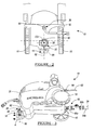
- the inlet connection 46 and the outlet connection 48 be arranged about a common lateral axis 56, which is best illustrated in Figures 1 and 2, as this prevents the support structure 12 and pump mechanism 14 from crabbing to one side or the other when either of the high pressure discharge hose 20 or the garden hose 54 are pulled to move to relocate the pressure washer 10.
- the common lateral axis 56 extend through the center of gravity of the washer mechanism 11, as this aids in the reduction of crabbing.
- the inlet connection 46 and the outlet connection 48 may also be arranged about a common vertical axis 58 to further improve the mobility of the pressure washer 10.
- the electric cord 62 of the electric motor 50 is preferably configured and arranged to extend in a rearward direction, such as from the rear face of the housing 30 through the electrical cord aperture 36.
- the electric cord 62 be positioned so as to extend in a generally vertical plane that includes the common lateral axis 56 (i.e., the electric cord 62 extend along an axis that is generally parallel the common lateral axis 56) to further prevent the support structure 12 and pump mechanism 14 from crabbing to one side or the other when either of the high pressure discharge hose 20 or the garden hose 54 are pulled to move to relocate the pressure washer 10.
- the electric cord 62 is shown to include an integral strain relief structure 64 that is configured to engage the housing shells 30a in a conventional and well known manner so as to inhibit both rotation and axial sliding movement of the strain relief structure 64 relative to the housing 30.
- the inlet connection 46 may include any appropriate means for coupling the garden hose 54 thereto, including a conventional threaded nipple (not shown) or a conventional 1 ⁇ 4 tum bayonette connection.
- the inlet connection 46 includes a quick disconnect (i.e., a hydraulic poppet) coupling set 66, of the type that are well known in the art and commercially available from sources such as Snap-Tite Inc. of Erie, Pennsylvania or Gardena Group of Germany.
- the quick disconnect coupling set 66 includes a male portion 66a, which is coupled to the inlet of the water pump 44, and a female portion 66b, which is configured to be threadably coupled to the discharge end 54b of the garden hose 54.
- the quick disconnect coupling set 66 is preferably configured (e.g., valved) such that water does not flow through the female portion 66b when the male and female portions 66a and 66b are uncoupled from one another and the male and female portions 66a and 66b may be sealingly coupled to (or uncoupled from) one another in a conventional axially-engaging (axially-disengaging) manner while the water in the garden hose 54 is under pressure.
- the outlet connection 48 may likewise include any appropriate means for coupling the high pressure discharge hose 20 thereto, including a conventional threaded nipple (not shown).
- the outlet connection 48 preferably includes a quick disconnect coupling set 68, of the type that are well known in the art and commercially available from sources such as Snap-Tite Inc. of Erie, Pennsylvania or Gardena Group of Germany.
- the coupling set 68 may be different from the coupling set 66 due, for example, to differences in the pressure of the water flowing through coupling sets 66 and 68.
- the quick disconnect coupling set 68 includes a female portion 68a, which is coupled to the outlet of the water pump 44, and a male portion 68b, which is coupled to the high pressure discharge hose 20.
- the quick disconnect coupling set 68 is preferably configured (e.g., valved) such that water does not flow through the female portion 68a when the female and male portions 68a and 68b are uncoupled from one another and the female and male portions 68a and 68b may be sealingly coupled to (or uncoupled from) one another in a conventional axially-engaging (axially-disengaging) manner while the water pump 44 is operating.
- the rear wheels 16 may be mounted to the support structure 12 through any conventional means so as to be rotatable in a conventional manner about an axis 76 that extends generally laterally relative to the support structure 12.
- the rear wheels 16 may be mounted to a common axle (not shown) that is coupled to the support structure 12, or each of the rear wheels 16 may be mounted via a discrete axle (not shown), which may be unitarily formed with or without its associated rear wheel 16, and rotatably coupled to an appropriate structure, such as the support structure 12 or another structure coupled that is coupled to the support structure 12 (e.g., the handle assembly 24).
- the front caster wheel 18 is a conventionally constructed caster wheel of the type that is commercially available and as such, a detailed discussion of the construction of the front caster wheel 18 need not be provided herein.
- the front caster wheel 18 includes a mounting yoke 80, which is pivotably coupled to the support structure 12 about an axis 82 that is generally perpendicular to the axis 76 of the rear wheels 16, and a wheel 84, which is rotatably coupled to the mounting yoke 80 about an axis 86 that is oriented generally perpendicular to the axis 82.
- the mounting yoke 80 includes a pivot collar 90 and a pivot pin 92 that extends through and rotates in the pivot collar 90.
- the pivot collar 90 is engaged to the housing 30 so as to permit the pivot pin 92 to extend into the front receiving aperture 38. Accordingly, the front caster wheel 18 is permitted to pivot about the axis 82 in the direction of arrow A in Figure 3.
- the front caster wheel 18 may optionally include one or more brake mechanisms (not shown) for selectively inhibiting the mounting yoke 80 from rotating about the axis 82 and/or the wheel 84 from rotating about the axis 86.
- the high pressure discharge hose 20 and the wand 22 of the particular example provided differ from the prior art only in the use of the female and male portions 102a and 102b of a quick disconnect coupling set 102.
- the quick disconnect coupling set 102 may be identical to the quick disconnect coupling set 68, or it may be configured differently (i.e., non-interchangeably configured) so as to "key" the components of the pressure washer 10 to one another.
- the high pressure discharge hose 20 includes a conventional hose segment 104 with opposite ends that are coupled to the male and female portions 68a and 102a, respectively, of the quick disconnect coupling sets 68 and 102, respectively.
- the end of the high pressure discharge hose 20 having the male portion 68b may be selectively coupled to the female portion 68a that is coupled to the outlet connection 48 of the pump mechanism 14.
- the opposite end of the high pressure discharge hose 20 to which the female portion 102b is coupled may likewise be selectively coupled to the male portion 102a that is coupled in fluid connection to the wand 22. Configuration in this manner ensures that high pressure water will not flow through the outlet connection 48 and high pressure discharge hose 20 if they are not coupled in fluid connection to the high pressure discharge hose 20 and the wand 22, respectively.
- the handle assembly 24 of the particular example provided is fixedly but removably coupled to the support structure 12 via a plurality of threaded fasteners (not shown).
- the handle assembly 24 includes a pair of laterally spaced apart side members 120 that extend generally vertically upward from the support structure 12, a handle member 122 that interconnects the distal end of the side members 120 and a hose hanger 124.
- the hose hanger 124 is generally Z-shaped, having a first leg member 130, which is coupled to the side members 120 at a location between the proximal and distal ends of the side members 120, a second leg member 132, which extends forwardly of the first leg member 130, and an upwardly extending abutment member 134.
- the second leg member 132 is configured to receive coiled materials such as the high pressure discharge hose 20, the electric cord 62 and/or the garden hose 54 when the pressure washer 10 is not being used.
- the abutment member 134 and the first leg member 130 abut the opposite sides of the coiled materials to inhibit the coiled materials from disengaging the second leg member 132 in an unintended manner.
- Storage pockets 140 may also be formed into the side members 120 for storage of the wand 22 or other items that are commonly employed during the use and/or maintenance of the pressure washer 10.
- the quick connect coupling sets 66, 68 and 102 permit the user to open the water valve (not shown) to the garden hose 54, connect the garden hose 54 to the inlet connection 46, connect the high pressure discharge hose 20 to the outlet connection 48 and connect the wand to the high pressure discharge hose 20 in any order desired.
- the front caster wheel 18 and the rear wheels 16 permit the user to reposition the pressure washer 10 as needed without halting the pressure washing operation by simply pulling the pressure washer 10 to a desired location via the wand 22 and the high pressure discharge hose 20. If the power washer 10 is to be moved over relatively long distances, the user need only grasp the handle 40 and lift the power washer 10, or pivot the handle member 122 in a clockwise direction to pivot the power washer 10 such that its entire weight is borne by the rear wheels.
- a second pressure washer constructed in accordance with the teachings of the present invention is generally indicated by reference numeral 10'.
- the pressure washer 10' is generally similar to the pressure washer 10 of Figure 1, except for the configuration of the washer mechanism 11' and the handle assembly 24'.
- the support structure 12' of the washer mechanism 11' is illustrated to define a housing 30' having an upper housing shell half 30a' and a lower housing shell half 30b'.
- the lower housing shell half 30b' may be configured in a conventional manner to receive the rear wheels 16, including apertures formed therethrough for receiving an axle 200 or an axle plate 202, whether integrally formed with the lower housing shell half 30b' or a discrete component that is installed to the lower housing shell half 30b', to which one or both of the rear wheels 16 are rotatably coupled.
- the upper housing shell half 30a' is illustrated to define an inlet aperture 32' through which the inlet connection 46 extends and an outlet aperture 34' through which the outlet connection 48 extends.
- the upper housing shell half 30a' and the pump mechanism 14' are configured such that the outlet connection 48 is positioned along an axis 210 that extends through the center of gravity of the washer mechanism 11' (the axis 210 also happens to lie in a vertical plane that includes the longitudinal axis of the washer mechanism 11'), while the input connection is located somewhat laterally offset from the axis 210. While this configuration is relatively more mobile that the prior art pressure washers of which we are aware, some crabbing can be expected with this configuration for the reasons noted above.
- the electric cord 62 may extend from the opposite lateral side of the axis 210.
- the inlet connection 46 and the electric cord 62 need not be spaced symmetrically about the axis 210.
- the handle assembly 24' may be a discrete structure that is fixedly coupled via screws (not shown), for example, to the support structure 12' or it may be integrally formed therewith (e.g., as a part of the upper housing shell half 30a').
- the handle assembly 24' is a discrete structure that includes a wall member 220 and a laterally extending member 222 that is coupled to the distal side of the wall member 220.
- the handle assembly 24' is generally U-shaped, such that the lateral sides 222a of the laterally extending member 222 overlie the lateral sides 220a of the wall member 220.
- the wall member 220 and laterally extending member 222 are preferably contoured so as to define a gripping portion 228 that is configured to be engaged by the palmar surface and fingers of a user's hand when the user is gripping the handle assembly 24'.
- the lateral sides 220a and 222a of the wall member 220 and the laterally extending member 222 form a hose/cord wrap 230 about which the electrical cord 62 and/or the high pressure discharge hose 20 may be wrapped.
- the handle assembly 24 is configured such that it includes a bumper 234 that is able to cooperate with the rear wheels 16 to maintain the support structure 12' in a generally vertical orientation as illustrated in Figure 10.
- the inlet connection 46 is positioned somewhat forwardly relative to the support structure 12' as compared to the embodiment of Figure 1. This longitudinal offset permits the garden hose 54 to bend in response to contact with the ground in a manner that does not cause the garden hose 54 to exert a force onto the support structure 12' that would tend to push it into the horizontal orientation of Figure 5.
- a third pressure washer constructed in accordance with the teachings of the present invention is generally indicated by reference numeral 10".
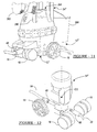
- the pressure washer 10" is generally similar to the pressure washer 10 of Figure 1, except that the pump mechanism 14" is illustrated to be arranged in a generally vertical manner, dual front caster wheels 18 are employed, and the support structure 12" and handle assembly 24" are constructed to provide additional storage (e.g., front pockets 260 for holding brush accessories 262 and a bucket hanger 264 on which a bucket 266 may be hung).
- the pressure washer 10" is relatively tall and as such, the inlet connection 46 and outlet connection 48 are positioned below the pressure washer's center of gravity so as to reduce the chance that the pressure washer 10" will tip when the high pressure discharge hose 20 or the garden hose 54 are pulled to reposition the pressure washer 10".
- the dual front caster wheels 18 are spaced apart by a sufficient dimension so that the outlet connection 48 and the high pressure discharge hose 20 do not inhibit the front caster wheels 18 from rotating through an angle of 360°.
- a fourth pressure washer constructed in accordance with the teachings of the present invention is generally indicated by reference numeral 10"'.
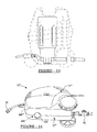
- Pressure washer 10"' is generally similar to pressure washer 10' ( Figure 5) in its construction and operation, but includes a front skid 400 rather than a front caster wheel.
- the front skid 400 is integrally formed with the support structure 12"' although those skilled in the art will appreciate that the front skid 400 may also be a discrete structure that is coupled to the support structure 12"'.
- the support structure 12"' includes a lower housing shell half 30b"' having a foot 402 that is positioned along an axis that lies in a vertical plane that intersects the center of gravity of the washer mechanism 11"'.
- the foot 402 is provided to support the front of the washer mechanism 11"' with relatively low frictional resistance so that the user may reposition the washer mechanism 11"' by simply pulling the high pressure discharge hose 20 or the garden hose 54.
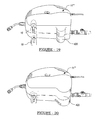
- the foot 402 may be configured in numerous ways, including for example, at least partially defined by a spherical radius as is shown in Figure 14, or defined a radius in planes that are parallel to the axis with a chamfer or radius being used to make the transition from the bottom of the foot 402 to the sides of the foot 402 as is shown in Figure 15, or generally flat with an upwardly rounded leading edge 410 as is shown in Figure 16.
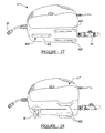
- FIG. 17 is generally similar to that of Figure 14, except that the rear wheels have also been replaced with one or more rear skids or feet 420.
- the rear feet 420 (or foot) is provided to support the rear of the washer mechanism 11"' with relatively low frictional resistance so that the user may reposition the washer mechanism 11"' by simply pulling the high pressure discharge hose 20 or the garden hose 54.
- Figures 18 through 20 are generally similar in concept to the embodiment of Figure 14, except that the rear wheels have been replaced by one or more feet 420, while one or more front caster wheels 18 are employed to support a front portion of the washer mechanism 11"'.
Landscapes
- Handcart (AREA)
- Details Of Reciprocating Pumps (AREA)
- Cleaning By Liquid Or Steam (AREA)
- Structures Of Non-Positive Displacement Pumps (AREA)
- Crystals, And After-Treatments Of Crystals (AREA)
- Electrical Discharge Machining, Electrochemical Machining, And Combined Machining (AREA)
- Encapsulation Of And Coatings For Semiconductor Or Solid State Devices (AREA)
- Secondary Cells (AREA)
Applications Claiming Priority (2)
| Application Number | Priority Date | Filing Date | Title |
|---|---|---|---|
| US10/230,915 US6892957B2 (en) | 2002-08-29 | 2002-08-29 | Pressure washer with improved mobility |
| US230915 | 2002-08-29 |
Publications (3)
| Publication Number | Publication Date |
|---|---|
| EP1393824A2 true EP1393824A2 (de) | 2004-03-03 |
| EP1393824A3 EP1393824A3 (de) | 2006-05-17 |
| EP1393824B1 EP1393824B1 (de) | 2008-12-17 |
Family
ID=31495379
Family Applications (1)
| Application Number | Title | Priority Date | Filing Date |
|---|---|---|---|
| EP03019443A Expired - Lifetime EP1393824B1 (de) | 2002-08-29 | 2003-08-28 | Mobiles Hochdruckreinigungsgerät |
Country Status (8)
| Country | Link |
|---|---|
| US (2) | US6892957B2 (de) |
| EP (1) | EP1393824B1 (de) |
| CN (1) | CN100544840C (de) |
| AT (1) | ATE417674T1 (de) |
| AU (1) | AU2003268175A1 (de) |
| CA (1) | CA2497147C (de) |
| DE (1) | DE60325306D1 (de) |
| WO (1) | WO2004020108A1 (de) |
Cited By (10)
| Publication number | Priority date | Publication date | Assignee | Title |
|---|---|---|---|---|
| EP1704923A1 (de) * | 2005-12-14 | 2006-09-27 | Scott Wu | Spritzgerät |
| WO2009106481A1 (de) | 2008-02-25 | 2009-09-03 | Robert Bosch Gmbh | Spritzpistolensystem |
| WO2012119641A3 (de) * | 2011-03-07 | 2012-11-22 | Alfred Kärcher Gmbh & Co. Kg | Beheizbares hochdruckreinigungsgerät |
| CN102874282A (zh) * | 2012-08-30 | 2013-01-16 | 樊荣 | 一种高压喷水手推车 |
| EP2659989A3 (de) * | 2012-05-02 | 2014-10-08 | BCPE La Norme | Autonomer Reiniger |
| CN104527610A (zh) * | 2014-12-19 | 2015-04-22 | 山西华龙城科贸发展有限公司 | 一种移动式小型汽车清洗装置 |
| CN108296195A (zh) * | 2017-12-20 | 2018-07-20 | 东莞理工学院 | 一种机械设备表面油污去除装置 |
| CN111924064A (zh) * | 2020-08-14 | 2020-11-13 | 杭州小橙工业设计有限公司 | 一种甲板清洗机 |
| USD981665S1 (en) | 2020-08-04 | 2023-03-21 | Generac Power Systems, Inc. | Pressure washer |
| US11752527B2 (en) | 2019-09-18 | 2023-09-12 | Generac Power Systems, Inc. | Pressure washer with container holder |
Families Citing this family (46)
| Publication number | Priority date | Publication date | Assignee | Title |
|---|---|---|---|---|
| US7753290B2 (en) * | 2002-10-15 | 2010-07-13 | Innovative Cleaning Equipment, Inc. | Portable powered foaming sprayer |
| US7083120B2 (en) * | 2003-11-04 | 2006-08-01 | Briggs & Stratton Power Products Group, Llc | Pressurized fluid delivery apparatus |
| US20050145270A1 (en) * | 2003-12-31 | 2005-07-07 | Ray R. K. | Pressure washer with injector |
| USD524999S1 (en) * | 2003-12-31 | 2006-07-11 | Campbell Hausfeld/Scott Fetzer Company | Spray lance and container |
| USD534698S1 (en) | 2003-12-31 | 2007-01-02 | Campbell Hausfeld/Scott Fetzer Company | Container for a spray lance |
| US7562780B2 (en) * | 2004-12-03 | 2009-07-21 | Briggs And Stratton Corporation | Accessory tray for a pressure washer |
| USD546509S1 (en) | 2004-12-06 | 2007-07-10 | Briggs And Stratton Corporation | Billboard for a pressure washer |
| US7891036B2 (en) * | 2005-03-18 | 2011-02-22 | Techtronic Outdoor Products Technology Limited | Multi-function power washer |
| US8444068B2 (en) | 2005-10-26 | 2013-05-21 | Techtronic Outdoor Products Technology Limited | Dual flow pressure washer |
| US7854398B2 (en) * | 2005-10-26 | 2010-12-21 | Techtronic Outdoor Products Technology Limited | Hand held pressure washer |
| MX2008006427A (es) * | 2005-11-16 | 2008-10-22 | Faip North America Inc | Lavadora de presion electrica manual. |
| US20070207043A1 (en) * | 2006-03-03 | 2007-09-06 | Eastway Fair Company Limited Of Trident Chambers | Enclosed vertically mounted engine |
| US20070207042A1 (en) * | 2006-03-03 | 2007-09-06 | Hahn Klaus K | Engine shroud |
| CA2672326A1 (en) * | 2006-11-28 | 2008-06-05 | Salvatore A. Alongi | Fluid spraying system |
| WO2008124082A1 (en) * | 2007-04-03 | 2008-10-16 | Faip North America, Inc. | Improved pressure washer |
| US7926740B2 (en) * | 2007-04-04 | 2011-04-19 | Black & Decker Inc. | Pressure washer system and operating method |
| US7516907B2 (en) * | 2007-05-04 | 2009-04-14 | Ecolab Inc. | Mobile foam producing unit |
| US8141754B2 (en) * | 2007-10-24 | 2012-03-27 | Techtronic Floor Care Technology Limited | Pressurized fluid dispenser |
| DE102008000394A1 (de) * | 2008-02-25 | 2009-08-27 | Robert Bosch Gmbh | Spritzpistolensystem |
| DK2271436T3 (en) * | 2008-04-24 | 2017-10-16 | Techtronic Outdoor Products Tech Ltd | SURFACE CLEANING SYSTEM |
| US8425203B2 (en) * | 2008-04-25 | 2013-04-23 | Techtronic Outdoor Products Technology Limited | Portable pressure washer system |
| US20110290914A1 (en) * | 2008-12-18 | 2011-12-01 | Olson Diane L | Hvlp toolbox sprayer |
| US8313309B1 (en) | 2009-01-30 | 2012-11-20 | Hawkins Bobby L | Wheeled, manually moveable pressure washer |
| USD634083S1 (en) | 2010-04-29 | 2011-03-08 | Briggs & Stratton Corporation | Pressure washer |
| USD633263S1 (en) | 2010-04-30 | 2011-02-22 | Briggs & Stratton Corporation | Pressure washer |
| US8556192B2 (en) | 2010-08-30 | 2013-10-15 | Todd W. Wise | Portable pressure washer |
| USD655467S1 (en) | 2010-11-16 | 2012-03-06 | Hawkins Bobby L | Frame for wheeled, manually moveable pressure washer |
| US8783587B2 (en) | 2011-03-14 | 2014-07-22 | Karcher North America, Inc. | Mobile washer unit |
| US8602323B2 (en) | 2011-03-14 | 2013-12-10 | Karcher North America | Mobile washer unit |
| WO2013123968A1 (de) * | 2012-02-20 | 2013-08-29 | Alfred Kärcher Gmbh & Co. Kg | Hochdruckreinigungsgerät |
| US8814531B2 (en) * | 2012-08-02 | 2014-08-26 | Briggs & Stratton Corporation | Pressure washers including jet pumps |
| WO2014146722A1 (de) * | 2013-03-22 | 2014-09-25 | Alfred Kärcher Gmbh & Co. Kg | Hochdruckreinigungsgerät |
| US20150014450A1 (en) * | 2013-07-10 | 2015-01-15 | Stephen M. Suden | Mobile pressure washer wand holder |
| DE202014000718U1 (de) | 2014-01-25 | 2015-04-28 | Nilfisk Advance A/S | Reinigungsgerät mit Halterung für eine Sprühpistole oder Lanze |
| USD743643S1 (en) * | 2014-03-05 | 2015-11-17 | Active Products Inc. | Pressure washer with retractable handle |
| AU2015358511B2 (en) * | 2014-12-05 | 2018-11-29 | Briggs & Stratton, Llc | Pressure washers including jet pumps |
| WO2017096740A1 (en) * | 2015-12-09 | 2017-06-15 | Ac (Macao Commercial Offshore) Limited | Improved power washer with pulsing boost power mode |
| EP3484638A4 (de) * | 2016-09-07 | 2019-10-23 | Sunrise Global Marketing | Hochdruckreiniger und verfahren zum betrieb eines hochdruckreinigers mit elektronischer druck-/flusssteuerung und anzeige |
| CN106733847A (zh) * | 2016-12-28 | 2017-05-31 | 上海亿力电器有限公司 | 一种小车式高压清洗机 |
| US10876761B2 (en) | 2018-03-29 | 2020-12-29 | Northern Tool & Equipment Company, Inc. | Combustion chamber gasket for use with a pressure washer |
| WO2020117994A1 (en) * | 2018-12-04 | 2020-06-11 | Melnor, Inc. | Improved traveling sprinkler systems and methods |
| US11346579B2 (en) | 2019-04-24 | 2022-05-31 | Karcher North America, Inc. | Vented cover plate |
| CN110562212B (zh) * | 2019-09-05 | 2021-06-11 | 肖春明 | 一种汽车全方位冲车装置 |
| CN214304212U (zh) * | 2021-03-09 | 2021-09-28 | 绿田机械股份有限公司 | 一种微型清洗机用泵单元 |
| US12508618B2 (en) | 2021-04-26 | 2025-12-30 | Black & Decker Inc. | Pressure washer with roll cage |
| USD1097389S1 (en) | 2023-11-09 | 2025-10-07 | Karcher North America, Inc. | Pressure washer |
Citations (1)
| Publication number | Priority date | Publication date | Assignee | Title |
|---|---|---|---|---|
| FR2713962A1 (fr) | 1993-12-22 | 1995-06-23 | Pavarini Srl | Nettoyeuse à jet d'eau, à savoir appareil destiné au nettoyage des surfaces au moyen d'un jet d'eau sous pression pouvant être éventuellement mélangée à un détergent. |
Family Cites Families (32)
| Publication number | Priority date | Publication date | Assignee | Title |
|---|---|---|---|---|
| US3310828A (en) | 1964-06-10 | 1967-03-28 | Direct Sales Inc | Vacuum cleaner |
| US3885892A (en) | 1973-05-29 | 1975-05-27 | Black & Decker Mfg Co | Housing assembly for air compressor and the like |
| US3913837A (en) * | 1974-08-13 | 1975-10-21 | Marshall D Grant | Spray/jet washing device |
| US3940065A (en) * | 1975-03-14 | 1976-02-24 | Graco Inc. | Portable spraying apparatus |
| US4238074A (en) * | 1976-12-23 | 1980-12-09 | Scott Coons | Attendant propelled portable spraying apparatus |
| DE3619326A1 (de) | 1986-06-09 | 1987-12-10 | Josef Kraenzle | Pumpeneinheit |
| US4865255A (en) * | 1987-12-03 | 1989-09-12 | Luvisotto Roy G | Self-contained, mobile spraying apparatus |
| US4926904A (en) * | 1988-08-08 | 1990-05-22 | Power Flo Products Corp. | Pressure washer |
| US5409032A (en) * | 1989-01-17 | 1995-04-25 | Shop Vac Corporation | Pressure washer bypass valve |
| US5040950A (en) | 1989-08-07 | 1991-08-20 | Northland Aluminum Products, Inc. | Power washing apparatus |
| DE3931814A1 (de) | 1989-09-23 | 1991-04-04 | Black & Decker Inc | Handgefuehrter hochdruckreiniger |
| DE4108775A1 (de) | 1991-03-18 | 1992-09-24 | Kaercher Gmbh & Co Alfred | Hochdruckreinigungsgeraet |
| DE9109717U1 (de) | 1991-08-06 | 1991-09-19 | Fa. Andreas Stihl, 7050 Waiblingen | Gehäuse für ein Hochdruckreinigungsgerät |
| DE4132670A1 (de) | 1991-10-01 | 1993-04-08 | Kaercher Gmbh & Co Alfred | Hochdruck-reinigungsgeraet |
| DE4327156C1 (de) * | 1993-08-12 | 1994-10-06 | Kaercher Gmbh & Co Alfred | Fahrbares Hochdruckreinigungsgerät |
| US5358385A (en) | 1993-09-16 | 1994-10-25 | Nancy Wang | Dual diaphragm pump with adjustable discharge side pressure trip switch |
| US5419497A (en) * | 1994-03-15 | 1995-05-30 | Warrington; Bruce | Portable pumping station |
| CA2191967C (en) | 1994-06-17 | 2000-03-21 | Josef Schneider | High-pressure cleaning appliance with safety insulation |
| US5700137A (en) | 1995-07-28 | 1997-12-23 | Gp Companies, Inc. | Low profile positive displacement pump system |
| DE19544876C2 (de) * | 1995-12-01 | 1998-10-29 | Guenter Kirsten | Hochdruckreinigungsgerät |
| US5975423A (en) | 1996-03-29 | 1999-11-02 | Rice; Terrence D. | Portable fully self-contained pressure wash-down system and method |
| US5624238A (en) | 1996-05-28 | 1997-04-29 | Herbert; Graham R. | Portable water pump for use with swimming pools |
| US5902094A (en) * | 1997-01-09 | 1999-05-11 | Generac Portable Products, Llc | Flow control valve for a pressure washer |
| US6158677A (en) | 1997-08-18 | 2000-12-12 | Charles Coles | Power washer wand |
| DE19737490A1 (de) * | 1997-08-28 | 1999-03-04 | Gardena Kress & Kastner Gmbh | Verfahren zum Betreiben einer Hochdruckvorrichtung, insbesondere eines Hochdruckreinigers und Hochdruckvorrichtung |
| DE29717390U1 (de) * | 1997-09-30 | 1998-02-26 | Wap Reinigungssysteme Gmbh & Co, 89287 Bellenberg | Hochdruckreinigungsgerät mit Schlauchtrommel |
| DE19747318C1 (de) * | 1997-10-27 | 1999-05-27 | Kaercher Gmbh & Co Alfred | Reinigungsgerät |
| US6070808A (en) * | 1998-05-18 | 2000-06-06 | Hygeian Technologies, Ltd. | Mobile spraying and cleaning apparatus |
| US6189811B1 (en) | 1999-11-15 | 2001-02-20 | David Owen Rudy | Portable water-pumping system |
| USD464471S1 (en) | 2001-10-31 | 2002-10-15 | Campbell Hausfeld/Scott Fetzer Company | Electric pressure washer |
| US6651909B1 (en) * | 2002-05-20 | 2003-11-25 | Adolfo Arteaga Bugarin | Spray nozzle retention apparatus and method |
| USD484471S1 (en) * | 2003-04-29 | 2003-12-30 | Benq Corporation | Monitor |
-
2002
- 2002-08-29 US US10/230,915 patent/US6892957B2/en not_active Expired - Fee Related
-
2003
- 2003-08-25 CA CA2497147A patent/CA2497147C/en not_active Expired - Fee Related
- 2003-08-25 CN CNB038246600A patent/CN100544840C/zh not_active Expired - Fee Related
- 2003-08-25 WO PCT/US2003/026588 patent/WO2004020108A1/en not_active Ceased
- 2003-08-25 AU AU2003268175A patent/AU2003268175A1/en not_active Abandoned
- 2003-08-28 AT AT03019443T patent/ATE417674T1/de not_active IP Right Cessation
- 2003-08-28 DE DE60325306T patent/DE60325306D1/de not_active Expired - Lifetime
- 2003-08-28 EP EP03019443A patent/EP1393824B1/de not_active Expired - Lifetime
-
2005
- 2005-04-28 US US11/116,763 patent/US7198204B2/en not_active Expired - Fee Related
Patent Citations (1)
| Publication number | Priority date | Publication date | Assignee | Title |
|---|---|---|---|---|
| FR2713962A1 (fr) | 1993-12-22 | 1995-06-23 | Pavarini Srl | Nettoyeuse à jet d'eau, à savoir appareil destiné au nettoyage des surfaces au moyen d'un jet d'eau sous pression pouvant être éventuellement mélangée à un détergent. |
Cited By (13)
| Publication number | Priority date | Publication date | Assignee | Title |
|---|---|---|---|---|
| EP1704923A1 (de) * | 2005-12-14 | 2006-09-27 | Scott Wu | Spritzgerät |
| WO2009106481A1 (de) | 2008-02-25 | 2009-09-03 | Robert Bosch Gmbh | Spritzpistolensystem |
| WO2012119641A3 (de) * | 2011-03-07 | 2012-11-22 | Alfred Kärcher Gmbh & Co. Kg | Beheizbares hochdruckreinigungsgerät |
| CN103415354A (zh) * | 2011-03-07 | 2013-11-27 | 阿尔弗雷德·凯驰两合公司 | 能够加热的高压清洗设备 |
| EP2659989A3 (de) * | 2012-05-02 | 2014-10-08 | BCPE La Norme | Autonomer Reiniger |
| CN102874282A (zh) * | 2012-08-30 | 2013-01-16 | 樊荣 | 一种高压喷水手推车 |
| CN104527610A (zh) * | 2014-12-19 | 2015-04-22 | 山西华龙城科贸发展有限公司 | 一种移动式小型汽车清洗装置 |
| CN108296195A (zh) * | 2017-12-20 | 2018-07-20 | 东莞理工学院 | 一种机械设备表面油污去除装置 |
| US11752527B2 (en) | 2019-09-18 | 2023-09-12 | Generac Power Systems, Inc. | Pressure washer with container holder |
| US20240024926A1 (en) * | 2019-09-18 | 2024-01-25 | Generac Power Systems, Inc. | Pressure washer with container holder |
| USD981665S1 (en) | 2020-08-04 | 2023-03-21 | Generac Power Systems, Inc. | Pressure washer |
| USD1075195S1 (en) | 2020-08-04 | 2025-05-13 | Generac Power Systems, Inc. | Mobile chassis portion of a pressure washer |
| CN111924064A (zh) * | 2020-08-14 | 2020-11-13 | 杭州小橙工业设计有限公司 | 一种甲板清洗机 |
Also Published As
| Publication number | Publication date |
|---|---|
| US20040046044A1 (en) | 2004-03-11 |
| EP1393824A3 (de) | 2006-05-17 |
| CN1694766A (zh) | 2005-11-09 |
| CN100544840C (zh) | 2009-09-30 |
| ATE417674T1 (de) | 2009-01-15 |
| AU2003268175A1 (en) | 2004-03-19 |
| CA2497147A1 (en) | 2004-03-11 |
| US6892957B2 (en) | 2005-05-17 |
| US20050205688A1 (en) | 2005-09-22 |
| CA2497147C (en) | 2011-08-02 |
| US7198204B2 (en) | 2007-04-03 |
| DE60325306D1 (de) | 2009-01-29 |
| EP1393824B1 (de) | 2008-12-17 |
| WO2004020108A1 (en) | 2004-03-11 |
Similar Documents
| Publication | Publication Date | Title |
|---|---|---|
| CA2497147C (en) | Portable pressure washer with linear movement | |
| EP2271436B1 (de) | Oberflächenreinigungssystem | |
| EP2954813B1 (de) | Bodenwerkzeug für eine reinigungsvorrichtung | |
| US7832991B2 (en) | Air compressor with removable manifold | |
| US5657509A (en) | Vacuum extractor | |
| US6923627B1 (en) | Air compressor with extensible handle bar assembly | |
| US8677553B2 (en) | Surface treating appliance | |
| US8438699B2 (en) | Surface treating appliance | |
| US6742995B1 (en) | Air compressor assembly | |
| AU745342B2 (en) | A handle for a vacuum cleaner | |
| US20080257988A1 (en) | Dual Flow Pressure Washer | |
| US20070125878A1 (en) | Hand held pressure washer | |
| US5048148A (en) | Carpet cleaning apparatus | |
| US20110088211A1 (en) | Surface treating appliance | |
| US7509706B2 (en) | Battery-powered portable vacuum | |
| US20110088210A1 (en) | Surface treating appliance | |
| US6086049A (en) | Mechanical assistance mechanism for shovels | |
| US20170312777A1 (en) | Cart sprayer | |
| AU2009329308B2 (en) | Floor tool for a cleaning appliance | |
| CA2527336A1 (en) | Cleaning station |
Legal Events
| Date | Code | Title | Description |
|---|---|---|---|
| PUAI | Public reference made under article 153(3) epc to a published international application that has entered the european phase |
Free format text: ORIGINAL CODE: 0009012 |
|
| AK | Designated contracting states |
Kind code of ref document: A2 Designated state(s): AT BE BG CH CY CZ DE DK EE ES FI FR GB GR HU IE IT LI LU MC NL PT RO SE SI SK TR |
|
| AX | Request for extension of the european patent |
Extension state: AL LT LV MK |
|
| PUAL | Search report despatched |
Free format text: ORIGINAL CODE: 0009013 |
|
| AK | Designated contracting states |
Kind code of ref document: A3 Designated state(s): AT BE BG CH CY CZ DE DK EE ES FI FR GB GR HU IE IT LI LU MC NL PT RO SE SI SK TR |
|
| AX | Request for extension of the european patent |
Extension state: AL LT LV MK |
|
| 17P | Request for examination filed |
Effective date: 20060614 |
|
| AKX | Designation fees paid |
Designated state(s): AT BE BG CH CY CZ DE DK EE ES FI FR GB GR HU IE IT LI LU MC NL PT RO SE SI SK TR |
|
| 17Q | First examination report despatched |
Effective date: 20071022 |
|
| GRAP | Despatch of communication of intention to grant a patent |
Free format text: ORIGINAL CODE: EPIDOSNIGR1 |
|
| GRAS | Grant fee paid |
Free format text: ORIGINAL CODE: EPIDOSNIGR3 |
|
| GRAA | (expected) grant |
Free format text: ORIGINAL CODE: 0009210 |
|
| AK | Designated contracting states |
Kind code of ref document: B1 Designated state(s): AT BE BG CH CY CZ DE DK EE ES FI FR GB GR HU IE IT LI LU MC NL PT RO SE SI SK TR |
|
| REG | Reference to a national code |
Ref country code: GB Ref legal event code: FG4D |
|
| REG | Reference to a national code |
Ref country code: CH Ref legal event code: EP |
|
| REG | Reference to a national code |
Ref country code: IE Ref legal event code: FG4D |
|
| REF | Corresponds to: |
Ref document number: 60325306 Country of ref document: DE Date of ref document: 20090129 Kind code of ref document: P |
|
| PG25 | Lapsed in a contracting state [announced via postgrant information from national office to epo] |
Ref country code: FI Free format text: LAPSE BECAUSE OF FAILURE TO SUBMIT A TRANSLATION OF THE DESCRIPTION OR TO PAY THE FEE WITHIN THE PRESCRIBED TIME-LIMIT Effective date: 20081217 Ref country code: SI Free format text: LAPSE BECAUSE OF FAILURE TO SUBMIT A TRANSLATION OF THE DESCRIPTION OR TO PAY THE FEE WITHIN THE PRESCRIBED TIME-LIMIT Effective date: 20081217 |
|
| PG25 | Lapsed in a contracting state [announced via postgrant information from national office to epo] |
Ref country code: RO Free format text: LAPSE BECAUSE OF FAILURE TO SUBMIT A TRANSLATION OF THE DESCRIPTION OR TO PAY THE FEE WITHIN THE PRESCRIBED TIME-LIMIT Effective date: 20081217 Ref country code: BG Free format text: LAPSE BECAUSE OF FAILURE TO SUBMIT A TRANSLATION OF THE DESCRIPTION OR TO PAY THE FEE WITHIN THE PRESCRIBED TIME-LIMIT Effective date: 20090317 Ref country code: ES Free format text: LAPSE BECAUSE OF FAILURE TO SUBMIT A TRANSLATION OF THE DESCRIPTION OR TO PAY THE FEE WITHIN THE PRESCRIBED TIME-LIMIT Effective date: 20090328 Ref country code: BE Free format text: LAPSE BECAUSE OF FAILURE TO SUBMIT A TRANSLATION OF THE DESCRIPTION OR TO PAY THE FEE WITHIN THE PRESCRIBED TIME-LIMIT Effective date: 20081217 Ref country code: EE Free format text: LAPSE BECAUSE OF FAILURE TO SUBMIT A TRANSLATION OF THE DESCRIPTION OR TO PAY THE FEE WITHIN THE PRESCRIBED TIME-LIMIT Effective date: 20081217 |
|
| PG25 | Lapsed in a contracting state [announced via postgrant information from national office to epo] |
Ref country code: SE Free format text: LAPSE BECAUSE OF FAILURE TO SUBMIT A TRANSLATION OF THE DESCRIPTION OR TO PAY THE FEE WITHIN THE PRESCRIBED TIME-LIMIT Effective date: 20090317 Ref country code: CZ Free format text: LAPSE BECAUSE OF FAILURE TO SUBMIT A TRANSLATION OF THE DESCRIPTION OR TO PAY THE FEE WITHIN THE PRESCRIBED TIME-LIMIT Effective date: 20081217 Ref country code: PT Free format text: LAPSE BECAUSE OF FAILURE TO SUBMIT A TRANSLATION OF THE DESCRIPTION OR TO PAY THE FEE WITHIN THE PRESCRIBED TIME-LIMIT Effective date: 20090518 Ref country code: AT Free format text: LAPSE BECAUSE OF FAILURE TO SUBMIT A TRANSLATION OF THE DESCRIPTION OR TO PAY THE FEE WITHIN THE PRESCRIBED TIME-LIMIT Effective date: 20081217 |
|
| PG25 | Lapsed in a contracting state [announced via postgrant information from national office to epo] |
Ref country code: SK Free format text: LAPSE BECAUSE OF FAILURE TO SUBMIT A TRANSLATION OF THE DESCRIPTION OR TO PAY THE FEE WITHIN THE PRESCRIBED TIME-LIMIT Effective date: 20081217 |
|
| PLBE | No opposition filed within time limit |
Free format text: ORIGINAL CODE: 0009261 |
|
| STAA | Information on the status of an ep patent application or granted ep patent |
Free format text: STATUS: NO OPPOSITION FILED WITHIN TIME LIMIT |
|
| PG25 | Lapsed in a contracting state [announced via postgrant information from national office to epo] |
Ref country code: DK Free format text: LAPSE BECAUSE OF FAILURE TO SUBMIT A TRANSLATION OF THE DESCRIPTION OR TO PAY THE FEE WITHIN THE PRESCRIBED TIME-LIMIT Effective date: 20081217 |
|
| 26N | No opposition filed |
Effective date: 20090918 |
|
| PG25 | Lapsed in a contracting state [announced via postgrant information from national office to epo] |
Ref country code: MC Free format text: LAPSE BECAUSE OF NON-PAYMENT OF DUE FEES Effective date: 20090831 |
|
| REG | Reference to a national code |
Ref country code: CH Ref legal event code: PL |
|
| PG25 | Lapsed in a contracting state [announced via postgrant information from national office to epo] |
Ref country code: LI Free format text: LAPSE BECAUSE OF NON-PAYMENT OF DUE FEES Effective date: 20090831 Ref country code: CH Free format text: LAPSE BECAUSE OF NON-PAYMENT OF DUE FEES Effective date: 20090831 |
|
| PG25 | Lapsed in a contracting state [announced via postgrant information from national office to epo] |
Ref country code: IE Free format text: LAPSE BECAUSE OF NON-PAYMENT OF DUE FEES Effective date: 20090828 |
|
| PG25 | Lapsed in a contracting state [announced via postgrant information from national office to epo] |
Ref country code: GR Free format text: LAPSE BECAUSE OF FAILURE TO SUBMIT A TRANSLATION OF THE DESCRIPTION OR TO PAY THE FEE WITHIN THE PRESCRIBED TIME-LIMIT Effective date: 20090318 |
|
| PG25 | Lapsed in a contracting state [announced via postgrant information from national office to epo] |
Ref country code: IT Free format text: LAPSE BECAUSE OF FAILURE TO SUBMIT A TRANSLATION OF THE DESCRIPTION OR TO PAY THE FEE WITHIN THE PRESCRIBED TIME-LIMIT Effective date: 20081217 |
|
| PG25 | Lapsed in a contracting state [announced via postgrant information from national office to epo] |
Ref country code: LU Free format text: LAPSE BECAUSE OF NON-PAYMENT OF DUE FEES Effective date: 20090828 |
|
| PG25 | Lapsed in a contracting state [announced via postgrant information from national office to epo] |
Ref country code: HU Free format text: LAPSE BECAUSE OF FAILURE TO SUBMIT A TRANSLATION OF THE DESCRIPTION OR TO PAY THE FEE WITHIN THE PRESCRIBED TIME-LIMIT Effective date: 20090618 |
|
| PG25 | Lapsed in a contracting state [announced via postgrant information from national office to epo] |
Ref country code: TR Free format text: LAPSE BECAUSE OF FAILURE TO SUBMIT A TRANSLATION OF THE DESCRIPTION OR TO PAY THE FEE WITHIN THE PRESCRIBED TIME-LIMIT Effective date: 20081217 |
|
| PG25 | Lapsed in a contracting state [announced via postgrant information from national office to epo] |
Ref country code: CY Free format text: LAPSE BECAUSE OF FAILURE TO SUBMIT A TRANSLATION OF THE DESCRIPTION OR TO PAY THE FEE WITHIN THE PRESCRIBED TIME-LIMIT Effective date: 20081217 |
|
| REG | Reference to a national code |
Ref country code: FR Ref legal event code: PLFP Year of fee payment: 14 |
|
| PGFP | Annual fee paid to national office [announced via postgrant information from national office to epo] |
Ref country code: NL Payment date: 20160810 Year of fee payment: 14 |
|
| PGFP | Annual fee paid to national office [announced via postgrant information from national office to epo] |
Ref country code: GB Payment date: 20160824 Year of fee payment: 14 Ref country code: DE Payment date: 20160823 Year of fee payment: 14 |
|
| PGFP | Annual fee paid to national office [announced via postgrant information from national office to epo] |
Ref country code: FR Payment date: 20160712 Year of fee payment: 14 |
|
| REG | Reference to a national code |
Ref country code: DE Ref legal event code: R119 Ref document number: 60325306 Country of ref document: DE |
|
| REG | Reference to a national code |
Ref country code: NL Ref legal event code: MM Effective date: 20170901 |
|
| GBPC | Gb: european patent ceased through non-payment of renewal fee |
Effective date: 20170828 |
|
| REG | Reference to a national code |
Ref country code: FR Ref legal event code: ST Effective date: 20180430 |
|
| PG25 | Lapsed in a contracting state [announced via postgrant information from national office to epo] |
Ref country code: NL Free format text: LAPSE BECAUSE OF NON-PAYMENT OF DUE FEES Effective date: 20170901 |
|
| PG25 | Lapsed in a contracting state [announced via postgrant information from national office to epo] |
Ref country code: GB Free format text: LAPSE BECAUSE OF NON-PAYMENT OF DUE FEES Effective date: 20170828 Ref country code: DE Free format text: LAPSE BECAUSE OF NON-PAYMENT OF DUE FEES Effective date: 20180301 |
|
| PG25 | Lapsed in a contracting state [announced via postgrant information from national office to epo] |
Ref country code: FR Free format text: LAPSE BECAUSE OF NON-PAYMENT OF DUE FEES Effective date: 20170831 |