EP1393876A1 - Verfahren zur Herstellung eines Schaumstoffkörpers aus einem thermoplastischen Kunststoff - Google Patents
Verfahren zur Herstellung eines Schaumstoffkörpers aus einem thermoplastischen Kunststoff Download PDFInfo
- Publication number
- EP1393876A1 EP1393876A1 EP02405722A EP02405722A EP1393876A1 EP 1393876 A1 EP1393876 A1 EP 1393876A1 EP 02405722 A EP02405722 A EP 02405722A EP 02405722 A EP02405722 A EP 02405722A EP 1393876 A1 EP1393876 A1 EP 1393876A1
- Authority
- EP
- European Patent Office
- Prior art keywords
- mold
- pressure
- tool cavity
- melt mass
- tool
- Prior art date
- Legal status (The legal status is an assumption and is not a legal conclusion. Google has not performed a legal analysis and makes no representation as to the accuracy of the status listed.)
- Withdrawn
Links
- 239000006260 foam Substances 0.000 title claims description 41
- 238000004519 manufacturing process Methods 0.000 title claims description 13
- 239000012815 thermoplastic material Substances 0.000 title 1
- 229920001169 thermoplastic Polymers 0.000 claims abstract description 39
- 239000004416 thermosoftening plastic Substances 0.000 claims abstract description 37
- 238000005187 foaming Methods 0.000 claims abstract description 29
- 238000000465 moulding Methods 0.000 claims abstract description 23
- 239000000155 melt Substances 0.000 claims abstract description 21
- 238000011049 filling Methods 0.000 claims abstract description 19
- 238000002347 injection Methods 0.000 claims abstract description 16
- 239000007924 injection Substances 0.000 claims abstract description 16
- 238000010438 heat treatment Methods 0.000 claims abstract description 5
- 238000000034 method Methods 0.000 claims description 54
- 239000004604 Blowing Agent Substances 0.000 claims description 45
- 238000005429 filling process Methods 0.000 claims description 31
- 238000001746 injection moulding Methods 0.000 claims description 19
- 229910001872 inorganic gas Inorganic materials 0.000 claims description 11
- 210000003298 dental enamel Anatomy 0.000 claims description 8
- 239000002131 composite material Substances 0.000 claims description 6
- 239000003380 propellant Substances 0.000 claims description 6
- 238000001514 detection method Methods 0.000 claims 1
- 238000011161 development Methods 0.000 abstract description 2
- 239000007787 solid Substances 0.000 abstract description 2
- 239000004088 foaming agent Substances 0.000 abstract 3
- 239000004014 plasticizer Substances 0.000 abstract 2
- 238000007630 basic procedure Methods 0.000 abstract 1
- 238000001816 cooling Methods 0.000 abstract 1
- 230000018109 developmental process Effects 0.000 abstract 1
- 239000007789 gas Substances 0.000 description 19
- 239000007858 starting material Substances 0.000 description 8
- PPBRXRYQALVLMV-UHFFFAOYSA-N Styrene Chemical compound C=CC1=CC=CC=C1 PPBRXRYQALVLMV-UHFFFAOYSA-N 0.000 description 6
- 238000002844 melting Methods 0.000 description 6
- 230000008018 melting Effects 0.000 description 6
- 229920003023 plastic Polymers 0.000 description 5
- 239000004033 plastic Substances 0.000 description 5
- 239000011148 porous material Substances 0.000 description 5
- 239000007921 spray Substances 0.000 description 5
- 239000000126 substance Substances 0.000 description 5
- XKRFYHLGVUSROY-UHFFFAOYSA-N Argon Chemical compound [Ar] XKRFYHLGVUSROY-UHFFFAOYSA-N 0.000 description 4
- IJGRMHOSHXDMSA-UHFFFAOYSA-N Atomic nitrogen Chemical compound N#N IJGRMHOSHXDMSA-UHFFFAOYSA-N 0.000 description 4
- CURLTUGMZLYLDI-UHFFFAOYSA-N Carbon dioxide Chemical compound O=C=O CURLTUGMZLYLDI-UHFFFAOYSA-N 0.000 description 4
- 229920001577 copolymer Polymers 0.000 description 4
- 239000010410 layer Substances 0.000 description 4
- 238000007789 sealing Methods 0.000 description 4
- 238000009826 distribution Methods 0.000 description 3
- OFBQJSOFQDEBGM-UHFFFAOYSA-N n-pentane Natural products CCCCC OFBQJSOFQDEBGM-UHFFFAOYSA-N 0.000 description 3
- -1 polyethylene Polymers 0.000 description 3
- 239000000243 solution Substances 0.000 description 3
- KAKZBPTYRLMSJV-UHFFFAOYSA-N Butadiene Chemical compound C=CC=C KAKZBPTYRLMSJV-UHFFFAOYSA-N 0.000 description 2
- 239000004743 Polypropylene Substances 0.000 description 2
- 239000004793 Polystyrene Substances 0.000 description 2
- 229910052786 argon Inorganic materials 0.000 description 2
- 238000009835 boiling Methods 0.000 description 2
- 229910002092 carbon dioxide Inorganic materials 0.000 description 2
- 239000001569 carbon dioxide Substances 0.000 description 2
- 238000010276 construction Methods 0.000 description 2
- 239000012792 core layer Substances 0.000 description 2
- 238000000354 decomposition reaction Methods 0.000 description 2
- PXBRQCKWGAHEHS-UHFFFAOYSA-N dichlorodifluoromethane Chemical compound FC(F)(Cl)Cl PXBRQCKWGAHEHS-UHFFFAOYSA-N 0.000 description 2
- 235000019404 dichlorodifluoromethane Nutrition 0.000 description 2
- 230000009969 flowable effect Effects 0.000 description 2
- 239000011521 glass Substances 0.000 description 2
- 239000007788 liquid Substances 0.000 description 2
- 238000002156 mixing Methods 0.000 description 2
- 239000000203 mixture Substances 0.000 description 2
- 229910052754 neon Inorganic materials 0.000 description 2
- GKAOGPIIYCISHV-UHFFFAOYSA-N neon atom Chemical compound [Ne] GKAOGPIIYCISHV-UHFFFAOYSA-N 0.000 description 2
- 229910052757 nitrogen Inorganic materials 0.000 description 2
- 229920000642 polymer Polymers 0.000 description 2
- 229920001155 polypropylene Polymers 0.000 description 2
- 239000004800 polyvinyl chloride Substances 0.000 description 2
- 229920002620 polyvinyl fluoride Polymers 0.000 description 2
- 229920005992 thermoplastic resin Polymers 0.000 description 2
- 230000001960 triggered effect Effects 0.000 description 2
- NLHHRLWOUZZQLW-UHFFFAOYSA-N Acrylonitrile Chemical compound C=CC#N NLHHRLWOUZZQLW-UHFFFAOYSA-N 0.000 description 1
- 239000004338 Dichlorodifluoromethane Substances 0.000 description 1
- VGGSQFUCUMXWEO-UHFFFAOYSA-N Ethene Chemical compound C=C VGGSQFUCUMXWEO-UHFFFAOYSA-N 0.000 description 1
- 239000005977 Ethylene Substances 0.000 description 1
- 241000237858 Gastropoda Species 0.000 description 1
- VVQNEPGJFQJSBK-UHFFFAOYSA-N Methyl methacrylate Chemical compound COC(=O)C(C)=C VVQNEPGJFQJSBK-UHFFFAOYSA-N 0.000 description 1
- 239000006057 Non-nutritive feed additive Substances 0.000 description 1
- CBENFWSGALASAD-UHFFFAOYSA-N Ozone Chemical compound [O-][O+]=O CBENFWSGALASAD-UHFFFAOYSA-N 0.000 description 1
- 229920002845 Poly(methacrylic acid) Polymers 0.000 description 1
- 239000004952 Polyamide Substances 0.000 description 1
- 239000004698 Polyethylene Substances 0.000 description 1
- 239000000654 additive Substances 0.000 description 1
- 239000002216 antistatic agent Substances 0.000 description 1
- 230000015572 biosynthetic process Effects 0.000 description 1
- 238000007664 blowing Methods 0.000 description 1
- 239000001273 butane Substances 0.000 description 1
- 239000002666 chemical blowing agent Substances 0.000 description 1
- KYKAJFCTULSVSH-UHFFFAOYSA-N chloro(fluoro)methane Chemical class F[C]Cl KYKAJFCTULSVSH-UHFFFAOYSA-N 0.000 description 1
- 230000000052 comparative effect Effects 0.000 description 1
- 238000011437 continuous method Methods 0.000 description 1
- 230000006378 damage Effects 0.000 description 1
- 230000006866 deterioration Effects 0.000 description 1
- 238000002845 discoloration Methods 0.000 description 1
- 230000000694 effects Effects 0.000 description 1
- 230000002996 emotional effect Effects 0.000 description 1
- 238000004880 explosion Methods 0.000 description 1
- 238000001125 extrusion Methods 0.000 description 1
- 239000000945 filler Substances 0.000 description 1
- 239000003063 flame retardant Substances 0.000 description 1
- 229920000578 graft copolymer Polymers 0.000 description 1
- 229910052736 halogen Inorganic materials 0.000 description 1
- 150000002367 halogens Chemical class 0.000 description 1
- 238000011065 in-situ storage Methods 0.000 description 1
- 239000003112 inhibitor Substances 0.000 description 1
- 239000012774 insulation material Substances 0.000 description 1
- IJDNQMDRQITEOD-UHFFFAOYSA-N n-butane Chemical compound CCCC IJDNQMDRQITEOD-UHFFFAOYSA-N 0.000 description 1
- 231100000252 nontoxic Toxicity 0.000 description 1
- 230000003000 nontoxic effect Effects 0.000 description 1
- 239000002667 nucleating agent Substances 0.000 description 1
- 239000003960 organic solvent Substances 0.000 description 1
- 230000003647 oxidation Effects 0.000 description 1
- 238000007254 oxidation reaction Methods 0.000 description 1
- 230000000704 physical effect Effects 0.000 description 1
- 239000002279 physical standard Substances 0.000 description 1
- 239000000049 pigment Substances 0.000 description 1
- 229920003229 poly(methyl methacrylate) Polymers 0.000 description 1
- 229920000058 polyacrylate Polymers 0.000 description 1
- 229920002647 polyamide Polymers 0.000 description 1
- 239000004417 polycarbonate Substances 0.000 description 1
- 229920000515 polycarbonate Polymers 0.000 description 1
- 229920000728 polyester Polymers 0.000 description 1
- 229920000573 polyethylene Polymers 0.000 description 1
- 239000004926 polymethyl methacrylate Substances 0.000 description 1
- 229920000098 polyolefin Polymers 0.000 description 1
- 229920002223 polystyrene Polymers 0.000 description 1
- 230000002028 premature Effects 0.000 description 1
- 238000002360 preparation method Methods 0.000 description 1
- 230000000750 progressive effect Effects 0.000 description 1
- 239000002994 raw material Substances 0.000 description 1
- 238000010107 reaction injection moulding Methods 0.000 description 1
- 229920005989 resin Polymers 0.000 description 1
- 239000011347 resin Substances 0.000 description 1
- 239000011342 resin composition Substances 0.000 description 1
- 239000008259 solid foam Substances 0.000 description 1
- 238000007711 solidification Methods 0.000 description 1
- 230000008023 solidification Effects 0.000 description 1
- 239000002904 solvent Substances 0.000 description 1
- 239000003381 stabilizer Substances 0.000 description 1
- 230000003068 static effect Effects 0.000 description 1
Images

Classifications
-
- B—PERFORMING OPERATIONS; TRANSPORTING
- B29—WORKING OF PLASTICS; WORKING OF SUBSTANCES IN A PLASTIC STATE IN GENERAL
- B29C—SHAPING OR JOINING OF PLASTICS; SHAPING OF MATERIAL IN A PLASTIC STATE, NOT OTHERWISE PROVIDED FOR; AFTER-TREATMENT OF THE SHAPED PRODUCTS, e.g. REPAIRING
- B29C44/00—Shaping by internal pressure generated in the material, e.g. swelling or foaming ; Producing porous or cellular expanded plastics articles
- B29C44/34—Auxiliary operations
- B29C44/3484—Stopping the foaming reaction until the material is heated or re-heated
-
- B—PERFORMING OPERATIONS; TRANSPORTING
- B29—WORKING OF PLASTICS; WORKING OF SUBSTANCES IN A PLASTIC STATE IN GENERAL
- B29C—SHAPING OR JOINING OF PLASTICS; SHAPING OF MATERIAL IN A PLASTIC STATE, NOT OTHERWISE PROVIDED FOR; AFTER-TREATMENT OF THE SHAPED PRODUCTS, e.g. REPAIRING
- B29C44/00—Shaping by internal pressure generated in the material, e.g. swelling or foaming ; Producing porous or cellular expanded plastics articles
- B29C44/02—Shaping by internal pressure generated in the material, e.g. swelling or foaming ; Producing porous or cellular expanded plastics articles for articles of definite length, i.e. discrete articles
- B29C44/022—Foaming unrestricted by cavity walls, e.g. without using moulds or using only internal cores
-
- B—PERFORMING OPERATIONS; TRANSPORTING
- B29—WORKING OF PLASTICS; WORKING OF SUBSTANCES IN A PLASTIC STATE IN GENERAL
- B29C—SHAPING OR JOINING OF PLASTICS; SHAPING OF MATERIAL IN A PLASTIC STATE, NOT OTHERWISE PROVIDED FOR; AFTER-TREATMENT OF THE SHAPED PRODUCTS, e.g. REPAIRING
- B29C44/00—Shaping by internal pressure generated in the material, e.g. swelling or foaming ; Producing porous or cellular expanded plastics articles
- B29C44/02—Shaping by internal pressure generated in the material, e.g. swelling or foaming ; Producing porous or cellular expanded plastics articles for articles of definite length, i.e. discrete articles
- B29C44/08—Shaping by internal pressure generated in the material, e.g. swelling or foaming ; Producing porous or cellular expanded plastics articles for articles of definite length, i.e. discrete articles using several expanding or moulding steps
Definitions
- the present invention relates to a method for producing a foam body made of a thermoplastic, according to the preamble of the claim 1, an apparatus for performing the method and use of the process product.
- Gas foaming processes in which the blowing agent is also known are also known is organic gas, the boiling point of which is not higher than the softening point of the Harzes is.
- the blowing agent is introduced into the molten resin under pressure and the mixture loaded with propellant is subsequently carried into an environment output lower pressure, which initiates the foaming process.
- organic Gases can, for example, butane, pentane or dichlorodifluoromethane (Freon R-12). Volatile organic liquids are also used.
- Blowing agents which also contain chlorofluorocarbon compounds pollute the environment, among other things for the destruction of the ozone layer be held responsible.
- thermoplastic resin in one Extruder converted into a flowable state and with an inorganic gas is loaded.
- the foaming process occurs when the gas-laden melt mass emerges triggered from the extruder nozzle into an environment of lower pressure.
- Foam body of larger cross-section e.g. cuboid foam blocks with dimensions of, for example, 120 x 240 x 30 cm are usually manufactured using so-called plunge edge tools.
- the procedure is characterized by the fact that in said plunge edge tool there is a molten liquid Prepared plastic mass and the plastic mass a physical or chemical blowing agent is added under pressure.
- the propellant-laden Plastic mass is then cooled to a block-shaped molded blank, solidified and removed from the plunge edge tool.
- Heating the blank for example in a corresponding one Oven, the mold blank is expanded into a foam block.
- the method mentioned has the disadvantage that the mixing of the Plastic mass with the blowing agent is often insufficient, resulting in an inhomogeneous Pore distribution leads. Furthermore, the method mentioned is not suitable for physical blowing agents which are gaseous under normal conditions.
- the object of the present invention is therefore to provide a method for producing large-dimensional, solid foam bodies with the most homogeneous pore distribution possible made of a thermoplastic using a propose gaseous blowing agent, in particular an inorganic gas.
- the object is achieved in that the propellant-laden thermoplastic melt mass produced in a plasticizing unit and using a delivery pressure from the plasticizing unit into the cavity of a closed one Forming tool is transported, and means are provided which during the mold filling on the thermoplastic conveyed into the mold Apply a back pressure which is less than the delivery pressure, the delivery pressure and the back pressure are greater than the foaming limit pressure, when the blowing agent falls below this, foaming of the thermoplastic Causes melt mass, and the thermoplastic melt mass solidified to form a blank after completion of the mold filling.
- thermoplastic melt mass is therefore contrary to that in the back pressure built up by the tool cavity.
- Means are provided which control the back pressure and / or the delivery pressure allow during the mold filling process.
- the plasticizing unit contains means for processing a thermoplastic Melt. These means preferably comprise a screw.
- the blowing agent or foam generator is preferably a under normal conditions or blowing agent present in gaseous form under atmospheric conditions.
- the term normal conditions here means the normal conditions for the physical Standard state, which a temperature of 0 ° C (standard temperature) and corresponds to a pressure of 101,325 Pa (standard pressure).
- the blowing agent is advantageously an inorganic gas.
- Preferred inorganic gases are, for example, CO 2 (carbon dioxide), N 2 (nitrogen), air, Ne (neon) or Ar (argon).
- CO 2 or CO 2 is particularly preferably used in the gas mixture with one or more further inorganic gases as the blowing agent.
- the blowing agent is expediently under pressure from the thermoplastic melt added in the plasticizing unit.
- thermoplastic melt mass is preferably included in the plasticizing unit a holding pressure, in particular a dynamic pressure, applied, the under Holding pressure standing thermoplastic melt the gaseous blowing agent is fed under pressure.
- the holding pressure is expediently greater than the foaming limit pressure.
- the foaming limit pressure is that on which Melting mass pressure exerted below which the blowing agent Foaming of the melt mass, i.e. cell formation.
- the holding pressure in the form of a dynamic pressure can be caused, for example, by the conveying force a screw arranged in the plasticizing unit can be generated.
- the plasticizing unit contains one or more in the cavity of the mold opening outlets.
- the outlet openings expedient with one or more closure nozzles, e.g. Needle valve nozzles, Mistake.
- the tool cavity of the Mold melt output after the mold filling is complete cooled, preferably cooled below their glass point, solidified, i.e. static stabilized, and subsequently demolded, with a blowing agent-loaded mold blank which arises under atmospheric pressure conditions and room temperature does not foam or expand.
- the blowing agent-loaded mold blank is used in a subsequent process step expanded or relaxed while heating to a foam body.
- To the blank is preferably placed in an appropriate oven (e.g. convection oven) transferred and expanded in it.
- the foaming process can be free, i.e. under atmospheric Pressure conditions, or performed under pressure.
- the foaming process can be done using molds.
- the foaming process can further develop the invention together with a subsequent RIM processing (reaction injection molding), e.g. for the production of sandwich composites.
- RIM processing reaction injection molding
- the invention can also cover layers in the form of resin-impregnated laminates (Prepreg) applied to the blank and in situ with the blank be laminated into a layered composite during the foaming process.
- the molding tool for producing the blank is expediently in several parts, preferably in two parts.
- the molding tool is preferably in a, a locking system included clamping unit, by means of which the mold is opened and closed.
- the locking unit is also used for application a tool locking force and to carry out the demolding process.
- the locking system can be operated mechanically or hydraulically.
- means for enlarging the Tool cavity of the mold provided during the mold filling process.
- the tool cavity becomes progressive Mold filling enlarged, the mold during the mold filling a, preferably permanent, back pressure on the tool cavity issued melt mass.
- the said back pressure is greater here than the foaming limit pressure.
- the mold is in several parts and contains at least a mold part movable during the mold filling process, the Tool cavity by means of a relative movement of the mold parts to one another during the mold filling process until a defined maximum size is reached is enlarged.
- the movable mold part (s) practice during the Form filling process a back pressure on the output in the tool cavity Melt mass from, wherein said back pressure is greater than the foaming limit pressure.
- the movable mold parts are preferred by hydraulically operating Operated means, i.e. emotional. These hydraulic means are preferred trained by the clamping unit itself.
- the molding tool is preferably in two parts with a first and a relative to first mold part, movable second mold part.
- Such one two-part molding tool can, for example, a so-called plunge edge tool be, wherein a first mold part as a in the second mold part engaging and formed relative to this linearly movable stamp is.
- the movable mold part is preferably an engaging in the tool cavity Stamp, the stamp under during the mold filling process Execution of an opening stroke enlarging the tool cavity from the Tool cavity is extended.
- the molding tool preferably contains one Distance device with which the opening stroke and thus the maximum cavity can be set to a predefined size.
- the mutual sealing of the mold parts is preferably done by the melt mass or its solidification product itself.
- the mold parts designed so that these at their cavity-side contact points, i.e. at the plunge edges with plunge edge tools, a narrow space form in the form of a gap which opens into the tool cavity.
- the Sealing effect is achieved in that melt mass in penetrates the intermediate space, fills it and through contact with the adjacent cool mold wall solidifies to a ridge and thus a further flow is prevented by enamel.
- the molding tool is on this Made gas-tight even by solidifying melt mass.
- the one described above Sealing concept is particularly suitable for two-part molds in the execution of a plunge edge tool.
- the gas pressure exerts a counter pressure during the mold filling process, which is greater than the foaming limit pressure, but lower than the delivery pressure.
- Gas can be supplied or removed via inlet or outlet valves. Doing so during the mold filling process, e.g. by means of pressure relief valves, expediently gas omitted the tool cavity, so that otherwise with increasing mold filling increasing gas pressure in the course of the mold filling process does not reduce the delivery pressure exceeds.
- the gas used to generate a positive gas pressure is preferably a gas which does not react as chemically as possible with the plastic mass.
- the gas can be, for example, an inorganic gas such as CO 2 (carbon dioxide), N 2 (nitrogen), air, Ne (neon) or Ar (argon).
- thermoplastic is preferably characterized by being when heated isotropic foaming under pressure relief.
- Isotropic foaming means that the pore geometry is independent of direction.
- the thermoplastic is therefore preferably an amorphous thermoplastic Plastic.
- the thermoplastic can be a polyolefin, e.g. polyethylene, Copolymer or polyblend of ethylene, polypropylene or copolymer or Polyblend of polypropylene, a styrene polymer, e.g. Polystyrene (PS), copolymer of polystyrene and polyblends thereof such as acrylonitrile / butadiene / styrene graft copolymer (ABS) or styrene / acrylonitrile copolymer (SAN), a halogen-containing Polymer, e.g.
- Polyvinyl chloride or polyvinyl fluoride (PVF), a polyester such as Polycarbonate, a polyamide, an acrylic polymer such as poly (methacrylic acid methyl ester) (PMMA) or another thermoplastic.
- the thermoplastic is a polyvinyl chloride (PVC).
- the method according to the invention is preferably by means of an injection molding device executed according to the characterizing features of claim 17.
- the injection molding device consists essentially of an injection unit and one that connects to the injection unit and contains a tool cavity Molding tool together.
- the molding tool works with a locking system containing locking unit together, which among other things the opening and Closing the mold is used.
- the interacting parts of the mold and the injection unit are expediently connected to one another in a pressure-tight manner.
- the injection unit contains, among other things, a plasticizing unit for the preparation of a Blowing agent-loaded, thermoplastic melt and a spray head.
- the blowing agent-loaded, thermoplastic melt mass is therefore by means of Injection molding introduced into the mold.
- the injection molding device contains means for supplying a gas which is gaseous under atmospheric conditions Blowing agent in the plasticizing unit.
- the plasticizing unit expediently contains a screw, by means of which the thermoplastic Melt mass prepared and homogenized, i.e. mixed, and is promoted.
- the screw is preferably arranged in a heatable cylinder.
- Via a filling unit that interacts with the plasticizing unit the starting material necessary for the production of the thermoplastic melt mass feed to the plasticizing unit.
- the injection molding process is discontinuous or semi-continuous Method.
- a starting material is used to carry out the method according to the invention fed to the plasticizing unit via the filling unit. By applying heat the starting material is melted and screwed into a flowable thermoplastic melt mass transferred and homogenized.
- the Melt mass is applied in the plasticizing unit with a holding pressure, e.g. in shape of a dynamic pressure, applied and with one fed into the plasticizing unit Load the blowing agent, the blowing agent using a screw if possible is evenly mixed into the thermoplastic melt.
- the propellant can be introduced under pressure using a pump or a Compressor happen.
- the propellant supply is appropriate at that section of the plasticizing unit at which the melt mass is under a holding pressure (e.g. dynamic pressure), the holding pressure being greater than the foaming limit pressure is.
- thermoplastic melt mass loaded with blowing agent is subsequently removed by means of Screw is conveyed in the direction of the spray head and fed to a dosing room and dosed according to the size of the molded blank to be produced.
- the dosed Melting mass is subsequently by means of a piston over one or more Output openings in the tool cavity of the molding tool or injected.
- the melt mass is removed from the dosing chamber with a so-called delivery pressure output into the mold cavity, which is the actual injection molding equivalent.
- the dosing chamber can be a pre-chamber or the screw be an antechamber formed by the screw moving back.
- the delivery pressure is expediently affected by the melt mass that is metered Piston generated, the screw itself can act as a piston.
- the delivery pressure consists of the so-called injection pressure, by means of which the Is melted into the mold. Furthermore, the delivery pressure also include a reprint, e.g. after completion of the actual Injection molding process is used to compensate for the shrinkage and so long continues until the enamel is frozen at the gate.
- the mold blank preferably under the Glass point temperature, cooled, solidified and demolded.
- a new dosing process can start again, i.e. a next filling process to get prepared.
- an extrusion device may also be used can be used, such a device by comparative high holding and delivery pressures.
- the starting material is preferably in solid form, especially as a resin composition in granular form.
- the starting material and / or the thermoplastic If necessary, enamel can contain additives such as processing aids, Nucleating agents, antistatic agents, stabilizers, fillers, oxidation inhibitors, Pigments, flame retardants and other substances can be added.
- the starting material or the melt mass can be used before use chemical or physical blowing agents have already been added to a holding pressure be, the blowing agent added under holding pressure of the melt mass is the main blowing agent.
- the molded blank is preferably cuboid and the foam body produced therefrom is preferably a cuboid foam block, the lengths and Width dimensions, for example in the range from 50 to 500 cm, in particular are in the range of 100 to 300 cm and its height is in the range of e.g. 1 up to 100 cm, in particular from 3 to 50 cm.
- the molded blank and, accordingly, the foam body can also have any other complex three-dimensional shapes, whereby such forms, especially when using the second, with gas pressure working process solution.
- the foam body preferably has a closed-cell pore structure.
- the bulk density of the foam bodies produced by the process according to the invention can be, for example, in the range of light foams from 30 to 200 kg / m 3 or in the range of heavy foam of over 200 kg / m 3 .
- the foam bodies produced by the process according to the invention can e.g. as thermal insulation materials for construction or construction purposes or for articles in the leisure and sports area, possibly with the execution of further Processing steps can be used.
- Foam bodies are preferably cut into foam sheets and others Uses or processing steps supplied.
- the foam sheets can e.g. be laminated on one or both sides with cover layers and so Form layers of composite materials. Particularly preferably form the Foam sheets core layers made of sandwich composite elements.
- the present method and the method suitable for carrying out the method Apparatus enable the production of massive, large dimensions Foam bodies using inorganic gases as blowing agents, the foam bodies produced according to the invention in particular characterized by an even distribution of the pores with an isotropic orientation.
- the Injection molding device contains an injection unit 6 and an injection unit 6 connected molding tool 10, which with a clamping unit (not shown) interacts.
- the injection unit 6 contains a filling unit 3 for receiving of the starting material 9, a plasticizing unit with one in a cylinder housing 7 arranged screw 2, a drive unit 8 for driving the screw 2, a heater (not shown) for melting the raw material 9 in the Plasticizing unit and a spray head 5 with an outlet opening.
- the A blowing agent supply unit 4 is provided in the plasticizing unit.
- the snail 2 serves melting, conveying, compacting and homogenizing the thermoplastic Melt.
- the screw 2 is used for mixing and distributing of the gaseous blowing agent fed into the melt.
- a starting material 9 is used to carry out the method according to the invention fed via the filling unit 3 of the plasticizing unit to a thermoplastic Melting mass melted and homogenized by means of a screw and in the direction Spray head 5 conveyed.
- a gaseous Blowing agent is fed into the plasticizing unit and under which, through the screw mixed melt pressure applied to a dynamic pressure.
- the propellant-loaded melt mass is directed in the direction by means of screw 2 Spray head 5 conveyed, dosed and directly under pressure through the outlet opening cuboid mold cavity 11a of the mold 10 injected.
- the punchy The melt mass emerges from the plasticizing unit through a sealing nozzle controlled at the outlet opening.
- the injection molding device can also have a plurality of outlet openings containing closure nozzles.
- the interacting parts of the molding tool 10 and the injection unit 6 are connected to each other in a pressure-tight manner during the mold filling process.
- the tool cavity 11 is formed by a first and a second mold part 13, 14 educated.
- the first mold part 13 is designed in the second Mold part 14 formed relative to this feasible stamp, whereby the size of the tool cavity 11 can be changed.
- the stamp 13 is for this associated with a locking system (not shown), which part of the locking unit is.
- the stamp 13 is by means of a locking system during the mold filling process while performing an opening stroke relative to the second mold part 14 moves, during the mold filling process with the clamping unit over the Stamp a permanent counter pressure or guard locking pressure on the tool cavity 11 sprayed enamel 12 is exercised.
- the punch 13 is formed Tool cavity 11a of a defined minimum size in the second mold part 14 retracted.
- the degree of filling of the tool cavity 11 is increased by the die 13 Tool cavity 11b (see FIG. 2) until a defined maximum size is reached retracted from the second mold part 14.
- the enlargement the tool cavity 11a, b takes place while maintaining a counter pressure the melt mass 12 dispensed in the tool cavity 11a, b, the one produced Back pressure is less than the delivery pressure and greater than the foaming limit pressure, so the premature foaming of the blowing agent-laden Enamel is prevented until it solidifies to form the blank.
- the melt mass is cooled and solidified into a mold blank 15 and demoulded it.
- the molded blank 15 is used in a subsequent process step foamed with heat to a foam block (not shown).
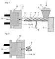
- Fig. 3 shows a schematic representation of a further injection molding device Production of blowing agent-loaded mold blanks according to the invention 15.
- Die Injection molding device contains an injection unit 26 and a molding tool 20.
- the injection molding device differs from that according to FIGS. 1 and 2 only in that the second arranged on the side of the injection unit 26 Mold part 24 as a stamp engaging in a first mold part 23 is formed and receives the outlet opening of the injection unit 26.
- the first Mold part 23 is assigned to the locking system (not shown), by means of which the first mold part 23 under during the mold filling process Exercise an opening stroke relative to the second mold part 24 lets, during the mold filling process with the locking system over the first Mold part 23 a counter pressure or holding pressure on the in the tool cavity 21 injected melt mass 25 is exercised.
Landscapes
- Chemical & Material Sciences (AREA)
- Chemical Kinetics & Catalysis (AREA)
- Injection Moulding Of Plastics Or The Like (AREA)
Abstract
Description
- Fig. 1:
- eine schematische Querschnittsansicht einer erfindungsgemässen Vorrichtung;
- Fig. 2:
- eine schematische Querschnittsansicht der erfindungsgemässen Vorrichtung nach Fig. 1 bei fortgeschrittenem Verfahrensverlauf;
- Fig. 3:
- eine schematische Querschnittsansicht einer weiteren erfindungsgemässen Vorrichtung;
- Fig. 4:
- einen gemäss erfindungsgemässen Verfahren hergestellten Formrohling vor dem Expandieren zu einem Schaumstoffblock.
Claims (26)
- Verfahren zur Herstellung eines Schaumstoffkörpers aus einem thermoplastischen Kunststoff, wobei eine Treibmittel-beladene, thermoplastische Schmelzmasse erzeugt und in ein Formwerkzeug überführt und zu einem Formrohling verfestigt wird, und der Formrohling entformt und unter Erwärmung zu einem Schaumstoffkörper geschäumt wird,
dadurch gekennzeichnet, dass
die Treibmittel-beladene, thermoplastische Schmelzmasse (12) in einer Plastifiziereinheit erzeugt und unter Anwendung eines Förderdruckes aus der Plastifiziereinheit in die Kavität (11) eines geschlossenen Formwerkzeuges (10) befördert wird, und Mittel vorgesehen sind, welche während der Formfüllung auf die in das Formwerkzeug (10) geförderte thermoplastische Schmelzmasse (12) einen Gegendruck ausüben, welcher kleiner ist als der Förderdruck, wobei der Förderdruck und der Gegendruck grösser sind als der Schäumungsgrenzdruck, bei dessen Unterschreiten das Treibmittel ein Aufschäumen der thermoplastischen Schmelzmasse bewirkt, und die thermoplastische Schmelzmasse nach Abschluss der Formfüllung zu einem Treibmittel-beladenen Formrohling (15) verfestigt wird. - Verfahren nach Anspruch 1, wobei das Treibmittel ein unter atmosphärischen Bedingungen gasförmiges Treibmittel ist.
- Verfahren nach einem der Ansprüche 1 bis 2, wobei das Treibmittel ein anorganisches Gas, vorzugsweise CO2 oder N2, ist.
- Verfahren nach einem der Ansprüche 1 bis 3, wobei das Treibmittel in der Plastifiziereinheit der Schmelzmasse zugeführt wird.
- Verfahren nach einem der Ansprüche 1 bis 4, wobei die Schmelzmasse in der Plastifiziereinheit mit einem Haltedruck, insbesondere Staudruck, beaufschlagt wird und der unter Haltedruck stehenden Schmelzmasse ein Treibmittel zugeführt wird, wobei der Haltedruck grösser ist als der Schäumungsgrenzdruck, bei dessen Unterschreiten das Treibmittel das Schäumen der Schmelzmasse bewirkt.
- Verfahren nach einem der Ansprüche 1 bis 5, wobei die Schmelzmasse (12) im Formwerkzeug (10) nach Abschluss der Formfüllung unter Ausbildung eines Formrohlings (15) abgekühlt, verfestigt und der Formrohling (15) anschliessend entformt wird.
- Verfahren nach Anspruch 6, wobei der entformte Formrohling (15) durch Wärmezufuhr, vorzugsweise unter atmosphärischen Druckverhältnissen, zu einem Schaumstoffkörper geschäumt wird.
- Verfahren nach einem der Ansprüche 1 bis 7, wobei Mittel zur Vergrösserung der Werkzeugkavität (11) des Formwerkzeuges (10) während des Formfüllvorganges vorgesehen sind, und die Werkzeugkavität (11) bei fortschreitender Formfüllung vergrössert wird, wobei das Formwerkzeug (10) während der Formfüllung einen Gegendruck auf die in die Werkzeugkavität (11) ausgegebene Schmelzmasse ausübt.
- Verfahren nach einem der Ansprüche 1 bis 8, wobei das Formwerkzeug (10) mehrteilig, vorzugsweise zweiteilig, ist und wenigstens ein bewegliches Formwerkzeugteil (13) enthält, wobei die Werkzeugkavität mittels einer Relativbewegung des oder der beweglichen Formwerkzeugteile (13) gegenüber dem oder den anderen Formwerkzeugteilen (14) während des Formfüllvorganges vergrössert wird, und das oder die beweglichen Formwerkzeugteile (13) während des Formfüllvorganges ein Gegendruck auf die in die Werkzeugkavität (11) ausgegebene Schmelzmasse (12) ausüben.
- Verfahren nach Anspruch 9, wobei das Formwerkzeug ein erstes und zweites Formwerkzeugteil (13, 14) enthält und das erste Formwerkzeugteil (13) als ein in das zweite Formwerkzeugteil (14) eingreifender Stempel ausgebildet ist, und die beiden Formwerkzeugteile (13, 14) unter Ausführung eines die Werkzeugkavität (11) vergrössernden Öffnungshubs relativ zueinander bewegt werden.
- Verfahren nach Anspruch 10, wobei das erste, als Stempel ausgebildete Formwerkzeugteil (13) beweglich ist und während des Formfüllvorganges aus der Werkzeugkavität (11) zurückgefahren wird und gleichzeitig einen Gegendruck auf die in die Werkzeugkavität (11) ausgegebene Schmelzmasse (12) ausübt.
- Verfahren nach einem der Ansprüche 1 bis 11, wobei in der Werkzeugkavität (11) ein Gasüberdruck aufgebaut wird und die thermoplastische Schmelzmasse mittels Förderdruck aus der Plastifiziereinheit in die Werkzeugkavität (11) gefördert wird, wobei der Gasüberdruck auf die Schmelzmasse einen Gegendruck ausübt, welcher kleiner ist als der Förderdruck.
- Verfahren nach Anspruch 12, wobei der Gasüberdruck in der Werkzeugkavität (11) während des Formfüllvorganges durch Mittel zur Gaszufuhr und Gasabfuhr, vorzugsweise Ein- und Auslassventile, gesteuert wird.
- Verfahren nach einem der Ansprüche 12 bis 13, wobei während des Formfüllvorganges zur Steuerung des Gasüberdruckes, Gas mittels Ventilen, insbesondere mittels Überdruckventilen, aus der Werkzeugkavität abgelassen wird.
- Verfahren nach einem der Ansprüche 1 bis 14, wobei die Werkzeugkavität (11), der Formrohling (15) und der aus diesem hergestellte Schaumstoffkörper quaderförmig sind.
- Verfahren nach Anspruch 15, wobei der quaderförmige Schaumstoffkörper zu Schaumstoffplatten geschnitten wird.
- Vorrichtung zur Herstellung von Schaumstoffkörpern nach dem Verfahren gemäss Anspruch 1 bis 16,
dadurch gekennzeichnet, dass
die Vorrichtung eine Spritzgiessvorrichtung mit einer Spritzeinheit (6), enthaltend eine Plastifiziereinheit zur Aufbereitung einer Treibmittel-beladenen thermoplastischen Schmelzmasse (12), einem an die Spritzeinheit (6) anschliessenden Formwerkzeug (10) und einer mit dem Formwerkzeug (10) zusammenwirkenden Schliesseinheit, umfasst und die Spritzgiessvorrichtung Mittel enthält, welche während des Formfüllvorganges auf die in das Formwerkzeug (10) geförderte thermoplastische Schmelzmasse einen Gegendruck ausüben. - Vorrichtung nach Anspruch 17, wobei Mittel (4) zur Zufuhr eines gasförmigen Treibmittels in die Plastifiziereinheit der Spritzeinheit (6) vorgesehen sind.
- Vorrichtung nach einem der Ansprüche 17 bis 18, wobei die Vorrichtung Mittel zur Veränderung der Grösse der Werkzeugkavität (11) während des Formfüllvorganges enthält, welche erlauben die Werkzeugkavität (11) während des Formfüllvorganges fortlaufend zu vergrössern, wobei während des Formfüllvorgangs durch das Formwerkzeug (10) ein Gegendruck auf die in die Werkzeugkavität (11) ausgegebene Schmelzmasse (12) ausgeübt wird.
- Vorrichtung nach einem der Ansprüche 17 bis 19, wobei das Formwerkzeug (10) mehrteilig ist und wenigstens ein bewegliches Formwerkzeugteil (13) enthält, mit welchem sich ein die Werkzeugkavität (11) vergrössernder Öffnungshub erzeugen lässt, wobei während des Formfüllvorgangs durch das bewegliche Formwerkzeugteil (13) ein Gegendruck auf die in die Werkzeugkavität (11) ausgegebene Schmelzmasse (12) ausgeübt wird.
- Vorrichtung nach einem der Ansprüche 17 bis 20, wobei das Formwerkzeug (10) ein erstes und zweites Formwerkzeugteil (13, 14) enthält und das erste Formwerkzeugteil (13) ein in die Werkzeugkavität (11) des zweiten Formwerkzeugteils (14) eingreifender Stempel ist, und das erste und zweite Formwerkzeugteil (13, 14) relativ zueinander verschiebbar angeordnet sind, so dass die Grösse der Werkzeugkavität (11) durch eine Relativbewegung der beiden Formwerkzeugteile (13, 14) zueinander verändert werden kann.
- Vorrichtung nach Anspruch 21, wobei der Stempel während des Formfüllvorganges unter Vergrösserung der mit der Schmelzmasse fortlaufend gefüllten Werkzeugkavität (11) bis Erreichen einer definierten Maximalgrösse aus dem zweiten Formwerkzeugteil (14) zurückfahrbar ist.
- Vorrichtung nach einem der Ansprüche 17 bis 22, wobei die Vorrichtung zur Ausübung eines Gegendruckes auf die Schmelzmasse Mittel zum Aufbau eines Gasüberdruckes in der Werkzeugkavität und Mittel zur Steuerung des Gasüberdruckes durch Gaszufuhr und Gasabfuhr während des Formfüllvorganges enthält.
- Vorrichtung nach Anspruch 23, wobei die Vorrichtung Einlass- und Auslassventile zum Einlass und Auslass von Gas in die oder aus der Werkzeugkavität enthält.
- Vorrichtung nach einem der Ansprüche 17 bis 24, wobei Mittel zur Erfassung des Gegendruckes und/oder des Förderdruckes sowie Mittel zur Steuerung des Gegendruckes und/oder des Förderdruckes während des Formfüllvorganges vorgesehen sind.
- Verwendung der Schaumstoffkörper hergestellt nach dem Verfahren gemäss Anspruch 1 bis 17 zur Fabrikation von Schaumstoffkernen von Sandwich-Verbundelementen.
Priority Applications (1)
| Application Number | Priority Date | Filing Date | Title |
|---|---|---|---|
| EP02405722A EP1393876A1 (de) | 2002-08-26 | 2002-08-26 | Verfahren zur Herstellung eines Schaumstoffkörpers aus einem thermoplastischen Kunststoff |
Applications Claiming Priority (1)
| Application Number | Priority Date | Filing Date | Title |
|---|---|---|---|
| EP02405722A EP1393876A1 (de) | 2002-08-26 | 2002-08-26 | Verfahren zur Herstellung eines Schaumstoffkörpers aus einem thermoplastischen Kunststoff |
Publications (1)
| Publication Number | Publication Date |
|---|---|
| EP1393876A1 true EP1393876A1 (de) | 2004-03-03 |
Family
ID=31198005
Family Applications (1)
| Application Number | Title | Priority Date | Filing Date |
|---|---|---|---|
| EP02405722A Withdrawn EP1393876A1 (de) | 2002-08-26 | 2002-08-26 | Verfahren zur Herstellung eines Schaumstoffkörpers aus einem thermoplastischen Kunststoff |
Country Status (1)
| Country | Link |
|---|---|
| EP (1) | EP1393876A1 (de) |
Cited By (5)
| Publication number | Priority date | Publication date | Assignee | Title |
|---|---|---|---|---|
| DE102006039099A1 (de) * | 2006-08-02 | 2008-02-07 | MöllerTech GmbH | Spritzgießverfahren zur Herstellung eines geschäumten Bauteils |
| DE102009038397A1 (de) | 2008-08-22 | 2010-02-25 | Magna Exteriors & Interiors Management Gmbh | Verfahren zur Herstellung spritzgegossener Schaumformteile und Schaumformteil |
| EP2537659A1 (de) * | 2011-06-24 | 2012-12-26 | Wittmann Battenfeld GmbH | Verfahren zum Spritzgiessen von Kunststoff-Formteilen aus thermoplastischem Kunststoff |
| WO2015088431A1 (en) | 2013-12-12 | 2015-06-18 | Diab International Ab | Apparatus and method for the production of expanded foam embryos |
| CN113001864A (zh) * | 2021-03-17 | 2021-06-22 | 山东大学 | 一种基于发泡注塑制坯的聚合物微发泡装置和工艺 |
Citations (6)
| Publication number | Priority date | Publication date | Assignee | Title |
|---|---|---|---|---|
| GB626151A (en) * | 1947-02-27 | 1949-07-11 | Expanded Rubber Co Ltd | Improvements in or relating to the production of cellular polyethylene |
| GB1247911A (en) * | 1968-07-25 | 1971-09-29 | Ici Ltd | Process for the production of cellular articles |
| US4133858A (en) * | 1977-12-14 | 1979-01-09 | Usm Corporation | Injection foam molding process |
| WO1996014978A1 (en) * | 1994-11-10 | 1996-05-23 | Reynaldo Oscar Oliver Silva | Process to manufacture articles in expanded reticular polymeric materials and the resulting products |
| US5834527A (en) * | 1995-07-14 | 1998-11-10 | Maschinenfabrik Hennecke Gmbh | Process for the manufacture of polyurethane foam moldings |
| EP1157798A2 (de) * | 2000-05-26 | 2001-11-28 | San Valeriano S.P.A. | Warmgeformten Formteil und Verfahren zu dessen Herstellung |
-
2002
- 2002-08-26 EP EP02405722A patent/EP1393876A1/de not_active Withdrawn
Patent Citations (6)
| Publication number | Priority date | Publication date | Assignee | Title |
|---|---|---|---|---|
| GB626151A (en) * | 1947-02-27 | 1949-07-11 | Expanded Rubber Co Ltd | Improvements in or relating to the production of cellular polyethylene |
| GB1247911A (en) * | 1968-07-25 | 1971-09-29 | Ici Ltd | Process for the production of cellular articles |
| US4133858A (en) * | 1977-12-14 | 1979-01-09 | Usm Corporation | Injection foam molding process |
| WO1996014978A1 (en) * | 1994-11-10 | 1996-05-23 | Reynaldo Oscar Oliver Silva | Process to manufacture articles in expanded reticular polymeric materials and the resulting products |
| US5834527A (en) * | 1995-07-14 | 1998-11-10 | Maschinenfabrik Hennecke Gmbh | Process for the manufacture of polyurethane foam moldings |
| EP1157798A2 (de) * | 2000-05-26 | 2001-11-28 | San Valeriano S.P.A. | Warmgeformten Formteil und Verfahren zu dessen Herstellung |
Cited By (9)
| Publication number | Priority date | Publication date | Assignee | Title |
|---|---|---|---|---|
| DE102006039099A1 (de) * | 2006-08-02 | 2008-02-07 | MöllerTech GmbH | Spritzgießverfahren zur Herstellung eines geschäumten Bauteils |
| DE102006039099B4 (de) * | 2006-08-02 | 2008-07-17 | MöllerTech GmbH | Spritzgießverfahren zur Herstellung eines geschäumten Bauteils |
| DE102009038397A1 (de) | 2008-08-22 | 2010-02-25 | Magna Exteriors & Interiors Management Gmbh | Verfahren zur Herstellung spritzgegossener Schaumformteile und Schaumformteil |
| EP2537659A1 (de) * | 2011-06-24 | 2012-12-26 | Wittmann Battenfeld GmbH | Verfahren zum Spritzgiessen von Kunststoff-Formteilen aus thermoplastischem Kunststoff |
| WO2015088431A1 (en) | 2013-12-12 | 2015-06-18 | Diab International Ab | Apparatus and method for the production of expanded foam embryos |
| EP3079878A4 (de) * | 2013-12-12 | 2017-10-04 | Diab International AB | Vorrichtung und verfahren zur herstellung expandierter schaumstoffperlen |
| US10357905B2 (en) | 2013-12-12 | 2019-07-23 | Diab International Ab | Apparatus and method for the production of expanded foam embryos |
| EP3750955A1 (de) * | 2013-12-12 | 2020-12-16 | Diab International AB | Vorrichtung und verfahren zur herstellung expandierter schaumstoffperlen |
| CN113001864A (zh) * | 2021-03-17 | 2021-06-22 | 山东大学 | 一种基于发泡注塑制坯的聚合物微发泡装置和工艺 |
Similar Documents
| Publication | Publication Date | Title |
|---|---|---|
| DE3152243C2 (de) | ||
| DE69228171T2 (de) | Verfahren zur Herstellung von Gegenständen aus Polymermaterial bestehend aus einem geschäumten Kern mit einer umhüllenden Schale, und Vorrichtung für dieses Verfahren | |
| DE102011105775B4 (de) | Verfahren zum Spritzgießen von Kunststoff-Formteilen aus thermoplastischem Kunststoff | |
| DE1778457B1 (de) | Verfahren zum herstellen von mehrschichtgegenstaenden | |
| DE2850700A1 (de) | Verbessertes spritzgussverfahren fuer schaumstoffe | |
| DE4236081A1 (de) | Verfahren zum Herstellen von Formkörpern aus geschäumtem Kunststoff und Form zur Ausübung dieses Verfahrens | |
| DE2461580A1 (de) | Verfahren zur herstellung geformter gegenstaende aus synthetischen harzen | |
| DE69405373T2 (de) | Verfahren und Vorrichtung zum Giessen von Formkörpern aus Kunststoff unterschiedlicher Dichte | |
| DE69924517T2 (de) | Geformter polymergegenstand | |
| EP1387751B1 (de) | Spritzgiessmaschine und spritzgiessverfahren zur herstellung geschäumter formteile | |
| EP2406052A2 (de) | Verfahren und vorrichtung zur herstellung von anguss-freien geschäumten bauteilen | |
| EP1162051B1 (de) | Verfahren und Vorrichtung zur Herstellung von geschäumten thermoplastischen Formteilen | |
| DE2922314A1 (de) | Verfahren und vorrichtung zur herstellung von formkoerpern aus schaeumbaren thermoplastischen kunststoffen | |
| DE19613134A1 (de) | Verfahren und Vorrichtung zum Herstellen von Kunststoffgegenständen | |
| EP1393876A1 (de) | Verfahren zur Herstellung eines Schaumstoffkörpers aus einem thermoplastischen Kunststoff | |
| DE1918075A1 (de) | Verfahren zur Herstellung von geschaeumten Kunststoffgegenstaenden durch Spritzgiessen und Vorrichtung zur Durchfuehrung des Verfahrens | |
| DE602004002481T2 (de) | Verfahren zur kontinuierlichen herstellung eines vollen, hohlen oder offenen profils | |
| WO2006136609A1 (de) | Vorrichtung und verfahren zur herstellung physikalisch getriebener schäume | |
| AT412767B (de) | Verfahren zum herstellen von länglichen gegenständen sowie mit diesem verfahren hergestellter gegenstand | |
| DE10355300A1 (de) | Verfahren zum Spritzgießen von Kunststoffmaterialien unter Verwendung von Gashaltedruck in der Form | |
| DE2348006C2 (de) | Verfahren und Vorrichtung zur Herstellung von Formteilen aus treibmittelhaltigem, thermoplastischem Kunststoff | |
| DE10226202A1 (de) | Herstellung von PP-Schaumpartikeln | |
| DE102008031391A1 (de) | Verfahren und Spritzgießwerkzeug zur Herstellung von Formteilen mit einer Schaumstruktur | |
| CH719093A1 (de) | Verfahren und Vorrichtung zur Herstellung einer geschäumten Polymercompositplatte aus Misch-Kunststoffabfall. | |
| DE19821397A1 (de) | Intrusionsverfahren zum Herstellen von Teilen aus recycelten Kunststoffen |
Legal Events
| Date | Code | Title | Description |
|---|---|---|---|
| PUAI | Public reference made under article 153(3) epc to a published international application that has entered the european phase |
Free format text: ORIGINAL CODE: 0009012 |
|
| AK | Designated contracting states |
Kind code of ref document: A1 Designated state(s): AT BE BG CH CY CZ DE DK EE ES FI FR GB GR IE IT LI LU MC NL PT SE SK TR |
|
| AX | Request for extension of the european patent |
Extension state: AL LT LV MK RO SI |
|
| 17P | Request for examination filed |
Effective date: 20040903 |
|
| AKX | Designation fees paid |
Designated state(s): AT BE BG CH CY CZ DE DK EE ES FI FR GB GR IE IT LI LU MC NL PT SE SK TR |
|
| 17Q | First examination report despatched |
Effective date: 20070124 |
|
| GRAP | Despatch of communication of intention to grant a patent |
Free format text: ORIGINAL CODE: EPIDOSNIGR1 |
|
| GRAS | Grant fee paid |
Free format text: ORIGINAL CODE: EPIDOSNIGR3 |
|
| STAA | Information on the status of an ep patent application or granted ep patent |
Free format text: STATUS: THE APPLICATION IS DEEMED TO BE WITHDRAWN |
|
| 18D | Application deemed to be withdrawn |
Effective date: 20090314 |