EP1394101A2 - Procédé de soudure selective de plaquettes - Google Patents
Procédé de soudure selective de plaquettes Download PDFInfo
- Publication number
- EP1394101A2 EP1394101A2 EP03019360A EP03019360A EP1394101A2 EP 1394101 A2 EP1394101 A2 EP 1394101A2 EP 03019360 A EP03019360 A EP 03019360A EP 03019360 A EP03019360 A EP 03019360A EP 1394101 A2 EP1394101 A2 EP 1394101A2
- Authority
- EP
- European Patent Office
- Prior art keywords
- substrate
- section
- connection surface
- connection
- substrates
- Prior art date
- Legal status (The legal status is an assumption and is not a legal conclusion. Google has not performed a legal analysis and makes no representation as to the accuracy of the status listed.)
- Withdrawn
Links
Images


Classifications
-
- B—PERFORMING OPERATIONS; TRANSPORTING
- B81—MICROSTRUCTURAL TECHNOLOGY
- B81C—PROCESSES OR APPARATUS SPECIALLY ADAPTED FOR THE MANUFACTURE OR TREATMENT OF MICROSTRUCTURAL DEVICES OR SYSTEMS
- B81C1/00—Manufacture or treatment of devices or systems in or on a substrate
- B81C1/00349—Creating layers of material on a substrate
- B81C1/00357—Creating layers of material on a substrate involving bonding one or several substrates on a non-temporary support, e.g. another substrate
-
- B—PERFORMING OPERATIONS; TRANSPORTING
- B81—MICROSTRUCTURAL TECHNOLOGY
- B81C—PROCESSES OR APPARATUS SPECIALLY ADAPTED FOR THE MANUFACTURE OR TREATMENT OF MICROSTRUCTURAL DEVICES OR SYSTEMS
- B81C2201/00—Manufacture or treatment of microstructural devices or systems
- B81C2201/01—Manufacture or treatment of microstructural devices or systems in or on a substrate
- B81C2201/0174—Manufacture or treatment of microstructural devices or systems in or on a substrate for making multi-layered devices, film deposition or growing
- B81C2201/019—Bonding or gluing multiple substrate layers
Definitions
- the present invention relates to a method for the selective connection of two substrates by means of wafer bonding as well as a component that is made by selective wafer bonding two substrates is made, and one substrate to manufacture such a device.
- DWB method direct wafer bonding processes
- the stable cohesive Connection of two substrates is based on one thermal or electrothermal joining and connection process.
- 7A to 7E show schematic Sectional representations of two substrates each through different DWB processes are connected.
- the illustrated Section planes are perpendicular to each two substrates or the boundary and connecting surface between the same.
- semiconductor-on-insulator bonding whose products are shown in FIGS. 7A and 7B, have both (Fig. 7A) or one (Fig. 7B) of the substrates 10, 12 oxidized surfaces or oxide layers 14, 15.
- SOI bonding involves the formation of a stable mechanical one Connection by a chemical or electrochemical, optionally thermally assisted reaction between the oxide layer 14 of the one substrate 10 and the oxide layer 15 or the oxide-free surface 16 of the other Substrate 12.
- Anodic bonding (AB), the products of which are shown in FIG. 7D 7E and 7E, a Pyrex layer 18 is deposited on top Substrate 10 applied or produced on this. Subsequently the pyrex layer is anodically bonded with a bare or oxide-free surface 16 of another Substrate 12 connected (Fig. 7D). Alternatively, use a Pyrex substrate 10 with a bare or oxide-free surface 16 of a semiconductor substrate 12 connected (FIG. 7E).
- mechanical Switching elements are spatially selective mechanical Inter-substrate connections desired, i. H. separate Sections of two surfaces of two substrates should be together are connected while other sections are not should be connected to each other even though they are each other touch.
- bond-preventing Layers or surfaces used are applied to sections Sections created that have no mechanical connection with a surface that they touch, shrink or form should.
- bond-preventing layers in addition to various Metals mainly used silicon nitride, which in particular is suitable for high-temperature bonding processes. Metal or silicon nitride layers can be made using standard techniques microsystem technology.
- the object of the present invention is a simplified process for mechanically connecting two Substrates as well as a component that connects two interconnected Has substrates, and a substrate for an inventive To create component.
- the present invention is based on the idea that Roughness of a surface of a first substrate spatially or laterally modulate in a predetermined manner to when bonding, especially wafer bonding, the surface of the first substrate with a surface of a second A corresponding spatially or laterally selective Get wafer bond connection.
- Sections of the surfaces of the two substrates each have one have low surface roughness, so between these sections formed a bond. If, however even one of the two opposite one another Sections of the surfaces of the two substrates are large Surface roughness does not occur with wafer bonding Bond connection formed.
- the present invention is also based on the finding assumes that a surface roughness of a surface of a Substrate on a process technically simple and easy controllable way enlarged by etching and by chemical-mechanical Polishing can be reduced.
- the present invention describes a selective method Bonding two or more wafers or substrates, which are preferably at least partially structured and further preferably a movable or elastic Have structure.
- Through surface treatment processes which include etching and polishing processes become sub-areas of contact surfaces of the substrates specifically for the connection process activated or deactivated. This allows between the contact surfaces of the connection partners a selective connection is predetermined.
- connection partners or substrates are joined together in such a way that their surfaces are at least partially touch.
- a thermomechanical or electrothermomechanical Treatment is in the activated contact areas creates a stable mechanical connection.
- An advantage of the invention is that sections of Surfaces of two substrates by wafer bonding or another connection method are connected to each other, can remain unbonded and then freely on top of each other can slide or be lifted from each other.
- the elasticity or flexibility of elastic structural areas is obtained and at the same time can be perpendicular to the touching but not connected Surface forces are transferred.
- Another advantage of the present invention is in that it is a laterally selective bonding of two substrates enabled by wafer bonding without additional To require layers of material. Oxidized or oxide-free surfaces of silicon or other semiconductor substrates, Pyrex coated substrates or Pyrex substrates be bonded.
- One application of the present invention is (micromechanical) Switching elements, micro valves, micro drives and Sensors etc., their rest position and switching forces via the mechanical preload of the moving structures defined and can be set depending on the process.
- Flexible mechanical structures are, for example, bending beams or membrane elements with or without center reinforcement.
- To generate a mechanical preload preferably a step profile in the rigid and / or in integrated the moving connection partner.
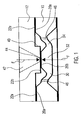
- Fig. 1 is a schematic sectional view of a component according to a first embodiment of the present Invention.
- the component is made of a first substrate 10 and a second substrate 12.
- the first Substrate 10 has a connection surface 20a, 20b
- the second substrate 12 has a bonding surface 22a, 22b.
- the section shown through the component is a vertical cut or a cut perpendicular to the connecting surfaces 20a, 20b, 22a, 22b.
- the substrates 10, 12 and the component formed from them are preferred essentially axially symmetrical to an axis, those perpendicular to the connection surfaces 20a, 20b, 22a, 22b is. This axis is also preferably in the shown cutting plane.
- a first portion 20a of the connection surface of the first Substrate 10 borders a first section 22a of the Connection surface of the second substrate 12 and is with this mechanically firmly connected by wafer bonding.
- the first substrate 10 has a preferably square, rectangular or circular membrane 30 with a central one Stiffening area 32 and an elastic area 34, which surrounds the stiffening area 32 in a ring.
- the membrane 30 or its stiffening area 32 and more elastic Area 34 are preferably through a lateral structured etching of the first substrate 10 of both Sides formed.
- the stiffening area 32 has a thickness due to which it is stiff in itself and by an outer Force is essentially undeformable.
- the elastic Area 34 is so thin that it passes through an external force is elastically deformable.
- the first portion 20a of the connection surface of the first Substrate 10 is arranged outside of membrane 30 and preferably encloses it in the lateral direction Completely.
- the second portion 20b of the connection surface of the first substrate 10 is at the stiffening area 32 arranged.
- first section 22a and the second section 22b has the connection surface of the second substrate 12 a step 40 so that the second section 22b opposite one defined by the first section 22a Plane protrudes toward the first substrate 10.
- the second section 20b and the first section 20a of FIG Connection surface of the first substrate 10 are included the production of the first substrate 10 in one plane.
- the protruding one causes second portion 22b of the connection surface of the second substrate 12 that the second portion 20b of the connection surface of the first substrate 10 or the stiffening area 32 of the membrane 30 deflected from its rest position and the elastic portion 34 is elastically deformed become.
- the second sections 20b, 22b of the Connection surfaces of the substrates 10, 12 against each other biased. That means they will be elastic Forces of the elastic region 34 with a force F on each other pressed.
- the amount of force F is from the dimensions and the thickness of the elastic portion 34 of the Membrane 30, of its material or its modulus of elasticity and the level 40 level.
- the component shown in FIG. 1 has in the second substrate 12 a through opening or a fluid line 42 on.
- An opening 44 of the fluid line 42 is in the middle of the second portion 22b of the connection surface of the second Arranged substrate 12 and is applied by the Stiffening area 32 or the adjacent second section 20b of the connection surface of the first substrate 10 closed fluid-tight.
- In the elastic region 34 of Membrane 30 can have a plurality of through openings or Fluid lines 46 may be arranged.
- the component shown is a micro valve.
- the opening 44 through the second section 22b of the connection surface of the second substrate 12 second section 20b of the connection surface of the first substrate 10 are sealed in a fluid-tight manner. Thereby there is no fluid communication between the fluid line 42 in the second substrate 12 and the fluid lines 46 in the first Substrate 10.
- an external force for example by fluid pressure, by an electrostatic, piezoelectric or a magnetic force, the membrane 30 or the stiffening area 32 against the force F even stronger be interpreted.
- the second section 20b the bonding surface of the first substrate 10 from the second portion 22b of the connection surface of the second Substrate 12 and lifted from the opening 44 of the fluid line 42. Fluid communication between the Fluid line 42 in the second substrate 12 and the fluid lines 46 in the first substrate 10.
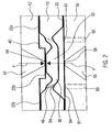
- Fig. 2 is a schematic sectional view of another Embodiment of a component according to the present invention.
- a vertical is shown again Section through the component.
- This embodiment differs from that shown in Fig. 1 Embodiment by a third substrate 50.
- the first Substrate 10 has a further connection surface 52 on, which is parallel to the first section 22a of the connection surface and essentially opposite arranged on the other side of the first substrate 10 is.
- the third substrate 50 has a connection surface 54 on which the further connection surface 52 of the touched the first substrate 10 and with this by wafer bonding connected is. Overall, this creates a sandwich arrangement in which the first substrate 10 is stacked between the second substrate 12 and the third substrate 50 is arranged.
- the third substrate 50 has a fluid line 56 which opposite the fluid line 42 of the second substrate 12 and with respect to the first substrate 10 essentially mirror-symmetrical is arranged to the same.
- the fluid line 56 has an opening 58 on the connection surface 52 of the third substrate 50.
- This opening 58 is the Stiffening area 32 of the membrane 30 opposite.
- the third substrate 5 50 preferably one or more fluid lines 60, whose openings 61 in the area of or opposite the elastic Area 34 are arranged. The openings 61 of the Fluid lines 60 are therefore through the stiffening area 32 of the membrane 30 even at its maximum deflection not closed.
- stiffening area 32 of the membrane 30 by a external force, for example a fluid pressure in the fluid line 42 in the second substrate 12, by an electrostatic, magnetic or piezoelectric force, from the opening 44 of the fluid line 42 in the second substrate 12 fluid communication between the Fluid line 42 in the second substrate 12 and the fluid lines 56 and 60 in the third substrate 50 through the fluid lines 46 in the membrane 30.
- a external force for example a fluid pressure in the fluid line 42 in the second substrate 12
- electrostatic, magnetic or piezoelectric force from the opening 44 of the fluid line 42 in the second substrate 12 fluid communication between the Fluid line 42 in the second substrate 12 and the fluid lines 56 and 60 in the third substrate 50 through the fluid lines 46 in the membrane 30.
- the microvalve shown in FIG. 2 is preferred operated so that the stiffening area 32 only exists in the two stop positions or only between switches it back and forth, and always only very temporarily in intermediate positions.
- the micro valve is therefore a classic 3/2-way switch valve with which between two alternative fluid paths (fluid line 42 - Fluid lines 60 or fluid line 56 - fluid line 60) can be switched.
- the stiffening region 32 of the membrane 30 is preferably moved electrostatically.
- the first substrate 10 including membrane 30 and the stiffening area 32 of the membrane 30 and the third substrate 50 an electrical conductive material, for example a semiconductor material on.
- the first substrate 10 and the third substrate 50 are between them by an insulating layer Connection surfaces 52, 54 electrically from each other isolated.
- This insulating layer is, for example Oxide layer caused by oxidation of the further connection surface 52 of the first substrate 10 and / or the connection surface 54 of the third substrate 50 is generated.
- the further connection surface 52 of the first substrate 10 and the connection surface 54 of the third substrate 50 by SOI bonding connected with each other.
- the membrane 30 and in particular its stiffening area 32 is an attractive one Force applied to the third substrate 50 or its connection surface 54 is directed. If the created Voltage is sufficiently high, the electrostatic generated Attraction between the stiffening area 32 of the Membrane 30 on the one hand and the third substrate 50 on the other hand greater than the force F with which the stiffening area 32 against the second portion 22b of the connection surface of the second substrate 12 is mechanically biased is. As a result, the stiffening area 32 is removed from the opening 44 of the fluid line 42 is lifted or the microvalve open. By varying the voltage applied the degree of opening and thus the flow resistance between the fluid line 42 in the second substrate 12 and the Fluid line 56 in the third substrate 50 can be varied.
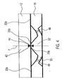
- FIGS. 1 and 2 show schematic sectional representations two ways to create a mechanical preload an elastic member or a membrane 30.
- the membrane 30 is as in FIGS. 1 and 2 Embodiments shown part of a first Substrate 10.
- a second substrate 12 is the first Opposite substrate 10 or its connecting surface 20a, 20b arranged but shown spaced.
- the Fig. 3A and 3B can be used as snapshots in the manufacturing process viewed immediately before joining the two substrates become.
- the membrane 30 or its elastic region 34 is still undeformed.
- Fig. 3A are a first section 20a and a second Section 20b of the connection surface of the first substrate 10 arranged coplanar or lie in the same plane. Between the first section 22a and the second section 22b of the joining surface of the second substrate 12 a step 40 is arranged so that the second section 22b with respect to the first section 22a in the direction protrudes to the first substrate 10. This will when connecting of the first portions 20a, 22a of the connection surfaces of the substrates 10, 12 the membrane 30 or its stiffening area 32 against the second section 22b of the Connection surface of the second substrate 12 mechanically biased.
- This geometry corresponds to that from the 1 and 2 illustrated embodiments. at which the mechanical preload also by one step 40 in the connection surface of the second substrate 12 is produced.
- 3A shows two variants of the first substrate 10.
- the one shown in the left half of the picture Substrate 10 is the elastic region 34 of membrane 30 by thinning the substrate 10 from both surfaces generated.
- the sections 20a, 20b of the connection surface of the first substrate 10 are therefore spatially apart spaced.
- the substrate shown in the right half of the picture 10 ' is membrane 30' only by thinning substrate 10 ' from the rear or the connecting surface 20a ', 20b 'opposite surface produced.
- the first Section 20a 'and the second section 20b' of the connection surface of the substrate 10 'thus merge.
- the first portion 20a 'of the connection surface of the substrate 10 ' for example, as the Section that is defined when connecting the Substrates 10 ', 12 the first section 22a of the connection surface touches and with the second substrate 12 is mechanically connected.
- the second section 20b 'on the connection surface of the first substrate 10 defined as the section that when connecting the Substrates 10 ', 12 the second section 22b of the connection surface touches the second substrate 12. If the Sections 20a ', 20b' are defined as they are from each other spaced.
- FIG. 3B shows the case complementary to FIG. 3A.
- the connection surface 22a, 22b of the second substrate 12 planar and has no level 40.
- the first paragraph 20a and the second portion 20b of the connection surface of the first substrate 10 are parallel to each other, however not coplanar. Instead, there is the second Section 20b towards the first section 20a in the direction onto the second substrate 12.
- 3B again shows two variants.
- the left half of the picture is between the elastic region 34 and the first portion 20a of the connection surface of the a first stage 62, and between the elastic region 34 and the second section 20b of the connection surface of the first substrate 10 or the stiffening area 32 is a second stage 64 arranged.
- the protrusion of the second section 20b of the Connection surface of the first substrate 10 opposite to the first section 20a results from a difference between the heights of steps 62, 64.
- the second sections 22b, 20b jump Connection surfaces of both substrates 10, 12 opposite the first sections of the same connection surface before to pre-tension the membrane produce.
- Fig. 4 is a schematic sectional view of another Embodiment of the present invention.
- This embodiment differs from that based on the embodiment shown in FIG. 1, that the connection surface 22a, 22b of the second substrate 12 has no level.
- the first section 22a and the second portion 22b of the connection surface of the second substrate 12 are rather coplanar or in one Level arranged.
- a bias of the reinforcement area 32 of the membrane 30 of the first substrate 10 and the second portion 20b of the connection surface of the first Substrate 10 against the second portion 22b of the connection surface of the second substrate 12 is based on the 3B way described above achieved.
- the second Section 20b of the connection surface of the first substrate 10 is in the relaxed state, d. H. in particular before assembling and connecting the substrates 10, 12, opposite the first portion 20a of the connection surface of the first substrate 10 via.
- the thickness of the stiffening area 32 of the membrane 30 as large as the thickness of the substrate 10 outside the membrane 30.
- a device according to the present Invention have the membrane 30 and its stiffening area 32 and its elastic region 34 preferably one Axis symmetry or a rotational symmetry to an axis perpendicular to the first connection surface 10.
- the membrane 30 has the shape of an ellipsoid, a rectangle, a general polygon, or any other shape.
- the stiffening area 32 of the membrane 30 ensures that the second portion 20b of the connection surface of the Substrate 10 even when the membrane 30 is deflected and is thus flat on the second section 22b of the connection surface of the second substrate 12 and the Opening 44 of fluid line 43 is closed in a fluid-tight manner.
- the membrane 30 has no stiffening area 32 on. The deflection of the membrane 30 from its rest position, the it occupies when no forces act on it, then has in usually also a deformation of the second section 20b the connection surface of the first substrate 10.
- a suitable design is, for example, in particular a rotational symmetry of the second portion 22b of the connection surface of the second Substrate 12 and step 40 relative to the same axis, with respect to which the membrane 30 is rotationally symmetrical is.
- the fluid lines 42, 46, 56, 60 are shown in FIGS Embodiments also symmetrical with respect to arranged the same axis of symmetry.
- one or multiple fluid lines 46 asymmetrical and / or outside of the elastic region 34 of the membrane 30 or in Stiffening area 32 arranged.
- the fluid line 56 in third substrate 50 may also like fluid line 60 also be arranged asymmetrically.
- the Fluid line 56 and its opening 58 arranged so that they even with a maximum deflection of the stiffening area 32, the same on the connecting surface 54 of the third substrate 50 is not closed.
- the fluid lines are arranged differently have a different course than that in FIGS. 1, 2 and 4 is shown. It is also particularly advantageous an arrangement of a second fluid line in the second substrate 12, so that both fluid connections of the valve on the same Side of the device are arranged.
- the valve is also suitable for fluids used in electrical Fields experience changes or with respect to electrical ones Fields are sensitive.
- an elastic is alternatively used Member used that an opening of a fluid line can close controlled, for example an elastic Bar.
- this is movable or elastic member biased so that it without external influence interrupts fluid communication by it closes an opening.
- the present invention is also many others mechanical or micromechanical components applicable, which is a stack of two or more substrates have selectively connected to each other by wafer bonding are.
- the present invention is particularly advantageous whenever only certain sections are touching Surfaces bonded together by wafer bonding should be, while other sections are not mechanical Connection should occur even though they are during wafer bonding touch each other.
- 1, 2 and 4 illustrated embodiments must be the first Sections 20a, 22a of the connection surfaces of the substrates 10, 12 mechanically connected to each other by wafer bonding become.
- the second portions 20b, 22b of the connection surfaces however, the substrates 10, 12 must not be mechanically connected to each other so that they can be opened of the valve can be easily separated from each other can.
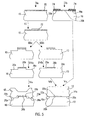
- the basic requirement for a stable DWB connection is one extremely high surface quality of the parts to be connected Surfaces of the substrates. Even the slightest wet or dry chemical Damage etchings a few nanometers deep a substrate surface so strong that a connection with a different surface by wafer bonding no longer is possible. Areas intended for a wafer bond connection a substrate surface must therefore not be included the known silicon etching processes are processed. Around the bondability of a substrate surface damaged by etching restore their surface quality be improved by means of a polishing process. This one The described selective bonding process takes advantage of this Facts to use.
- a first step Ia the surface or connection surface of one bonding partner 10 is first over-etched over the entire surface. This is done, for example, with hot 33 percent aqueous potassium hydroxide solution (KOH) with a minimum etching time of 10 minutes. A slightly roughened surface 70 is formed with a surface roughness or a roughness depth R z ⁇ 0.018 ⁇ m. Although this continues to be a reflective technical plan area, it is already unconditional. Roughness depth values given in this document refer to measurements with the TENCOR P11 profilometer.
- the roughness depth R z is a measure of the roughness of a surface. It is determined by profile measurements along n individual measuring sections. For each individual measuring section, the individual roughness depth is R zi , the sum of the height of the largest profile tip and the depth of the largest profile valley within the individual measuring section.
- the roughness depth R z is the arithmetic mean of the individual roughness depths
- the mask 72 faces preferably gold, chrome gold or gold on other adhesion promoters, such as B. WoTi.
- the layer thickness of the mask 72 is dependent on the processing time or the Thickness to be removed in a subsequent polishing step Layer at least 200 nm.
- a third step the portions of the roughened surface 70 that are not covered by the mask 72 are chemically and mechanically polished.
- a weakly caustic polishing solution preferably 3.3% aqueous KOH
- CMP chemical mechanical polishing process
- the process parameters can be used to set whether and to what extent the surface of the substrate 10 is simultaneously deep structured.
- Intensive chemical-mechanical polishing (IIIa) results in deep structuring, the lateral shape of which is determined by the mask 72.
- With minimal material removal (IIIb) only the roughened surface 70 is removed in order to improve the surface quality, and there is practically no deep structuring.
- the Po-5 lituring step produces an improved surface quality with a roughness depth R z ⁇ 0.014 ⁇ m, which meets the high quality requirements of wafer bonding.
- a fourth step IVa, IVb the mask 72 is removed.
- the result is a more or less deeply structured Surface 20a, 20b with bondable or activated Sections 20a and non-bondable or inactivated Sections 20b.
- a fifth step Va, Vb the substrate 10 is through Wafer bonding connected to a further substrate 12. If the bonding surface of the substrate 10 in the previous Steps deeply structured (IVa), the further substrate 12 a corresponding depth structuring or have sufficient elasticity (Va). If at the previous polishing process only a minimal deep structuring the surface 20a, 20b took place (IVb) can the substrate 10 with a stiff or inflexible further substrate 12 are connected (Vb). In both Cases form activated or bondable sections 20a Surface sections 22a of the further substrate 12 are stable, cohesive connections while inactivated or non-bondable sections 20b with surface sections 22b of the further substrate 12 even then no bond connection train when you touch them.
- surface sections of a substrate are therefore activated for a bond connection by producing a high surface quality or a low roughness depth R z by means of a polishing process. This is preferably done by chemical mechanical polishing. Sections of a connection surface of a substrate are inactivated for a bond connection by reducing their surface quality or increasing their roughness depth R z . This is preferably done by an etching step.
- connection surface 20a, 20b of a substrate 10 the first etching step 1b in those sections 20a a mask 74 which should not be deactivated.
- the etching step Ib are thus from the outset only those sections 20b etched or roughened which be deactivated for the subsequent bonding step should.
- the substrate can 10 then immediately in a step Vc by wafer bonding are connected to the further substrate 12.
- one of the two substrates selectively activated or deactivated.
- Both structured and unstructured substrates can be activated or deactivated with steps I - IV become.
- the further substrate 12 which is structured in FIG. 5 and in particular has a membrane, selectively activated and deactivated.
- Another alternative is selective activation and Deactivation of both substrates by polishing or etching.
- steps 40, 62, 64 or protruding portions 20b, 22b of the connection surfaces a mechanical preload of an elastic member can be generated. Because the deep structuring a connection surface during a polishing step controlled the manufacturing parameters of this polishing step (step IIIa), the rest position and contact pressure also become the elastic or movable structures through the manufacturing parameters set.
- FIG. 6 is a variant of the invention Manufacturing process described.
- Fig. 6 is again a schematic sectional view of a Component that the second shown in FIG. 2 Embodiment corresponds.
- the present one is suitable Invention especially for components that consist of substrate stacks two (FIG. 1) or more (FIG. 2) substrates 10, 12, 50 with elastic or movable, mechanically preloaded or members touching in the elastic areas 30 have.
- the substrates 10, 12 should be by means of a SOI bonding process or an SDS process selective be cohesively connected. A selective one Bonding using only certain sections of the connection surfaces it is necessary to form a bond connection to ensure the function of the component.
- the activated contact surfaces 20a, 22a are hydrophilic. Between they form hydrogen bonds, as a result of which the substrates even after removal of the external Adhesive force spontaneously adhere to one another.
- This adhesive force can be strengthened by the substrates when attached external contact pressure at temperatures between 400 ° C and 600 ° C to be heated. Solidify at these temperatures already in the pre-bonding phase described here chemical bonds between the contact surfaces. The stability the connection is thereby significantly increased, and it can also substrates with elastic members with high mechanical restoring forces are processed.
- the restoring force of an elastic member used for Purposes of generating a mechanical preload at Joining the substrates deflected from its rest position is reduced or according to the present invention switched off by electrostatically counteracting one Force exerted on the elastic member becomes.
- Silicon wafers or others are particularly suitable for this Semiconductor substrates 10, 12 which, as is customary in SOI bonding by an electrically insulating layer 14, 15 are separated. In this case, by applying an electrical Voltage between the first substrate 10 and an electrostatic field between the third substrate 50 the movable member 30 and the third substrate 50 become. In the case of a device that has only two substrates 10, 12, the electrical voltage between the first substrate 10 and an adjacent one Pressure plate created. The pressure plate is in this Case a pressure electrode plate.
- the elastic structure 30 of the third substrate 50 or the contact electrode plate By means of the electrical
- the elastic member 30 is therefore from the second substrate 12 or the second section 22b of the Connection surface of the second substrate 12 pulled away. This will force the elastic member to the second substrate 12 exercises, reduces or completely degrades.
- the bond between the first portion of the surface of the first substrate 10 and the first portion of the Surface of the second substrate 12 is thus in their Development phase and especially less in the pre-bonding phase or not at all by the elastic restoring force of the elastic member mechanically loaded. This allows the Adhesion of the substrates 10, 12 are stabilized so far that the substrates remain even after removing the external Contact pressure and the electrical voltage are no longer non-destructive let separate.
- the substrate stack is removed without any additional measures, d. H. especially without external joining force and without electrical voltage between the first substrate 10 and the third substrate 50 of the high temperature treatment of the Subjected to SOI bonding or the SDS procedure. at Temperatures between 800 ° C and 1100 ° C take place on the bond surfaces the complete chemical transformation of the hydrogen bonds into permanent atomic bonds instead of.
- the elastic Member 30 electrostatically at least during the pre-bonding phase deflected or from the second substrate 12 pulled away.
- the elastic member during of the entire bonding process or deflected by the second Substrate 12 pulled away.
- electrostatic instead of electrostatic as described alternatively to magnetostatic, piezoelectric or some other way a force on the elastic Member exercised.
Landscapes
- Engineering & Computer Science (AREA)
- Manufacturing & Machinery (AREA)
- Microelectronics & Electronic Packaging (AREA)
- Micromachines (AREA)
- Pressure Welding/Diffusion-Bonding (AREA)
- Pressure Sensors (AREA)
Applications Claiming Priority (2)
| Application Number | Priority Date | Filing Date | Title |
|---|---|---|---|
| DE2002139307 DE10239307A1 (de) | 2002-08-27 | 2002-08-27 | Verfahren zum selektiven Waferbonden |
| DE10239307 | 2002-08-27 |
Publications (2)
| Publication Number | Publication Date |
|---|---|
| EP1394101A2 true EP1394101A2 (fr) | 2004-03-03 |
| EP1394101A3 EP1394101A3 (fr) | 2005-09-14 |
Family
ID=31197434
Family Applications (1)
| Application Number | Title | Priority Date | Filing Date |
|---|---|---|---|
| EP03019360A Withdrawn EP1394101A3 (fr) | 2002-08-27 | 2003-08-27 | Procédé de soudure selective de plaquettes |
Country Status (2)
| Country | Link |
|---|---|
| EP (1) | EP1394101A3 (fr) |
| DE (1) | DE10239307A1 (fr) |
Cited By (1)
| Publication number | Priority date | Publication date | Assignee | Title |
|---|---|---|---|---|
| CN108516519A (zh) * | 2018-06-19 | 2018-09-11 | 苏州大学 | 磁控介质阻挡放电阳极键合系统及方法 |
Family Cites Families (2)
| Publication number | Priority date | Publication date | Assignee | Title |
|---|---|---|---|---|
| EP1076767B1 (fr) * | 1998-05-08 | 2002-02-06 | Infineon Technologies AG | Microsoupape |
| US7045878B2 (en) * | 2001-05-18 | 2006-05-16 | Reveo, Inc. | Selectively bonded thin film layer and substrate layer for processing of useful devices |
-
2002
- 2002-08-27 DE DE2002139307 patent/DE10239307A1/de not_active Ceased
-
2003
- 2003-08-27 EP EP03019360A patent/EP1394101A3/fr not_active Withdrawn
Cited By (1)
| Publication number | Priority date | Publication date | Assignee | Title |
|---|---|---|---|---|
| CN108516519A (zh) * | 2018-06-19 | 2018-09-11 | 苏州大学 | 磁控介质阻挡放电阳极键合系统及方法 |
Also Published As
| Publication number | Publication date |
|---|---|
| EP1394101A3 (fr) | 2005-09-14 |
| DE10239307A1 (de) | 2004-04-01 |
Similar Documents
| Publication | Publication Date | Title |
|---|---|---|
| DE102019203914B3 (de) | MEMS mit großer fluidisch wirksamer Oberfläche | |
| EP0517698B1 (fr) | Pompe microminiaturisee | |
| DE69806487T2 (de) | Mikromechanische vorrichtungen mit thermischer bogentraverse und zugehörige herstellungsverfahren | |
| DE69804352T2 (de) | Mikrostruktur mit einem verformbaren element durch einwirkung eines thermischen antriebes | |
| DE102014225934B4 (de) | Elektrostatisch auslenkbares mikromechanisches Bauelement und Verfahren zu seiner Herstellung | |
| DE69024935T2 (de) | Herstellungsverfahren für ein mikroventil | |
| EP0521117B1 (fr) | Microsoupape | |
| DE69609414T2 (de) | Elastomeres mikroelektromekanisches system | |
| EP4255844A1 (fr) | Mems présentant un couvercle d'entrainement et procédé de fonctionnement associé | |
| EP2556282B1 (fr) | Micro-soupape, methode de production et micro-pompe | |
| DE102015213756B4 (de) | Mikromechanische Struktur und Verfahren zur Herstellung derselben | |
| DE102017203722B4 (de) | Mems und verfahren zum herstellen derselben | |
| DE102007030121A1 (de) | Verfahren zur Herstellung eines Bauteils und Bauteil | |
| WO2008052762A2 (fr) | Dispositif semi-conducteur et procédé de fabrication d'un dispositif semi-conducteur | |
| EP1371092A1 (fr) | Procede de structuration d'un substrat plat en un materiau vitreux | |
| DE112011101117B4 (de) | Integrierter elektromechanischer Aktuator und Verfahren zur Herstellung desselben | |
| DE10239306B4 (de) | Verfahren zum selektiven Verbinden von Substraten | |
| EP1468436A1 (fr) | Systeme micro-electromecanique et procede de fabrication | |
| EP1394101A2 (fr) | Procédé de soudure selective de plaquettes | |
| DE102007058239B4 (de) | Mikrospiegelvorrichtung | |
| DE19800189A1 (de) | Mikromechanischer Schalter und Verfahren zur Herstellung desselben | |
| DE102008005521B4 (de) | Kapazitiver Wandler und Verfahren zur Herstellung desselben | |
| DE102010002818B4 (de) | Verfahren zur Herstellung eines mikromechanischen Bauelementes | |
| EP1246215B1 (fr) | Microrelais à nouvelle construction | |
| DE102004058103B4 (de) | Einrichtung zur Spalteinstellung |
Legal Events
| Date | Code | Title | Description |
|---|---|---|---|
| PUAI | Public reference made under article 153(3) epc to a published international application that has entered the european phase |
Free format text: ORIGINAL CODE: 0009012 |
|
| AK | Designated contracting states |
Kind code of ref document: A2 Designated state(s): AT BE BG CH CY CZ DE DK EE ES FI FR GB GR HU IE IT LI LU MC NL PT RO SE SI SK TR |
|
| AX | Request for extension of the european patent |
Extension state: AL LT LV MK |
|
| RIN1 | Information on inventor provided before grant (corrected) |
Inventor name: AUBER, JOHANNES Inventor name: NOMMENSEN, PETER Inventor name: SCHAIBLE, JOCHEN, DR. |
|
| PUAL | Search report despatched |
Free format text: ORIGINAL CODE: 0009013 |
|
| AK | Designated contracting states |
Kind code of ref document: A3 Designated state(s): AT BE BG CH CY CZ DE DK EE ES FI FR GB GR HU IE IT LI LU MC NL PT RO SE SI SK TR |
|
| AX | Request for extension of the european patent |
Extension state: AL LT LV MK |
|
| RAP1 | Party data changed (applicant data changed or rights of an application transferred) |
Owner name: HOERBIGER AUTOMATISIERUNGSTECHNIK HOLDING GMBH Owner name: HAHN-SCHICKARD-GESELLSCHAFT FUER ANGEWANDTEFORSCHU |
|
| AKX | Designation fees paid | ||
| STAA | Information on the status of an ep patent application or granted ep patent |
Free format text: STATUS: THE APPLICATION IS DEEMED TO BE WITHDRAWN |
|
| 18D | Application deemed to be withdrawn |
Effective date: 20060315 |
|
| REG | Reference to a national code |
Ref country code: DE Ref legal event code: 8566 |