EP1394473A2 - Hotte d'aspiration à placer au-dessus d'une zône de travail, en particulier un plan de cuisson - Google Patents
Hotte d'aspiration à placer au-dessus d'une zône de travail, en particulier un plan de cuisson Download PDFInfo
- Publication number
- EP1394473A2 EP1394473A2 EP20030017010 EP03017010A EP1394473A2 EP 1394473 A2 EP1394473 A2 EP 1394473A2 EP 20030017010 EP20030017010 EP 20030017010 EP 03017010 A EP03017010 A EP 03017010A EP 1394473 A2 EP1394473 A2 EP 1394473A2
- Authority
- EP
- European Patent Office
- Prior art keywords
- housing
- vapor
- extractor hood
- bearing part
- vapor shield
- Prior art date
- Legal status (The legal status is an assumption and is not a legal conclusion. Google has not performed a legal analysis and makes no representation as to the accuracy of the status listed.)
- Withdrawn
Links
- 238000010411 cooking Methods 0.000 title 1
- 238000007789 sealing Methods 0.000 claims description 10
- 239000013536 elastomeric material Substances 0.000 claims description 5
- 230000008054 signal transmission Effects 0.000 claims description 2
- 239000000565 sealant Substances 0.000 description 8
- 238000011161 development Methods 0.000 description 7
- 230000018109 developmental process Effects 0.000 description 7
- 239000003517 fume Substances 0.000 description 3
- 238000009434 installation Methods 0.000 description 2
- 230000002093 peripheral effect Effects 0.000 description 2
- 230000000630 rising effect Effects 0.000 description 2
- 238000011109 contamination Methods 0.000 description 1
- 230000000694 effects Effects 0.000 description 1
- 238000000605 extraction Methods 0.000 description 1
- 239000011521 glass Substances 0.000 description 1
- 230000005484 gravity Effects 0.000 description 1
- 239000000463 material Substances 0.000 description 1
Images



Classifications
-
- F—MECHANICAL ENGINEERING; LIGHTING; HEATING; WEAPONS; BLASTING
- F24—HEATING; RANGES; VENTILATING
- F24C—DOMESTIC STOVES OR RANGES ; DETAILS OF DOMESTIC STOVES OR RANGES, OF GENERAL APPLICATION
- F24C15/00—Details
- F24C15/20—Removing cooking fumes
- F24C15/2078—Removing cooking fumes movable
- F24C15/2092—Removing cooking fumes movable extendable or pivotable
Definitions
- the invention relates to an extractor device for arrangement above a work area, in particular hob, the type mentioned in the preamble of claim 1.
- Such an extractor device is for example by the applicant under the Type designation DA 249-2 sold, see the Leporello with the No. 418319-8 / 00 from Miele & Cie., hingersloh.
- the well-known extractor device is about arrangement a work area designed as a hob and is in the assembled state fixed to a wall with an enclosure.
- a vapor screen is fixed to the housing arranged, which partially surrounds the housing and is substantially transverse to Longitudinal axis of the housing extends.
- the known extractor device allows the Gap between the edge facing the wall in the assembled state and the wall small in size, so that the accumulating above the work area rises Wrasens is largely avoided.
- a disadvantage of the known extractor device is that the location of the fume screen does not affect different body sizes of users can be adjusted.
- the invention thus faces the problem of the known extractor device in this way to further develop that the location of the vapor screen to different body sizes from Is adjustable.
- an extractor device is known from DE 74 33 594, in which the Vapor screen is designed to be lowerable towards the hob.
- the vapor screen in the known Extractor device not arranged on the housing of the extractor device, but, like the rest of the extractor hood, is inside a kitchen wall unit integrated and forms the extension of the kitchen wall unit in the lowered state towards the hob.
- the vapor screen is here extends essentially in the direction of the longitudinal axis of the housing.
- the Vapor umbrella U-shaped so that in the area of the wall of the vapors from Vapor umbrella can rise freely.
- the advantages that can be achieved with the invention include the adjustability of the Vapor umbrella to different body sizes in particular that the Distance between the mounting level of the housing of the extractor hood and the in the assembled state of the wall facing edge of the vapor screen essentially stays the same. In this way it is possible despite the adjustability of the vapor screen
- the gap between the wall and the vapor screen should be so small that the amount of over a work area that creates vapors that rise between the wall and the vapor screen, can be significantly reduced.
- a suitable sealant For example, a sealing lip made of an elastomeric material, the gap between the wall and vapors are essentially sealed airtight. It is irrelevant whether the sealant is arranged on the wall and / or on the vapor screen.
- sealant can generally be selected within wide limits.
- a advantageous embodiment of the aforementioned embodiment provides that the sealant as sealing lip arranged on the vapor shield is formed from an elastomeric material, since such a sealing lip is an inexpensive standard component.
- Adjustment device arranged on the housing and essentially in the direction the longitudinal axis and a first longitudinal guide extending in this first longitudinal guide Movable and arranged on the vapor screen first bearing part. This is the teaching of the invention in a particularly simple and therefore inexpensive manner realized.
- An advantageous embodiment of the aforementioned embodiment provides that the Adjustment device arranged on the housing parallel to and spaced from the first longitudinal guide second longitudinal guide and one in this second longitudinal guide movable and arranged on the vapor screen spaced from the first bearing part has second bearing part. In this way, safe and robust management of the Vapor screen reached on the housing.
- the adjusting device on the housing has an articulated guide and on the vapor screen a third bearing part, the third bearing part is designed to be movable in the articulated guide. This is a safe one and space-saving guidance of the vapor shield on the housing is realized.
- a practical design of the aforementioned embodiment provides that the articulated guide spaced from the first longitudinal guide and the third bearing part is formed spaced from the first bearing part.
- Adjustment device a hinge designed as a bracket arranged on the housing and the vapor shield is a fourth bearing part which engages in the holder in the assembled state or vice versa. In this way, the number of components and the space required Adjustment device is reduced and a visually particularly appealing design of the Extractor hood device reached.
- the adjustment device has at least one Has securing means, the vapor shield through the securing means in each set position can be determined automatically. This ensures that the location the vapor shield relative to the housing is not changed in an undesirable manner.
- a manually operated adjustment device is generally sufficient.
- a special one An advantageous further development of the teaching according to the invention provides that the adjustment device one with an electronic control unit of the extractor device in Signal transmission connection standing electric actuator, by means of which Position of the vapor screen as a function of electrical signals from the electronic Control unit is adjustable. In this way, for example, is a non-contact Adjustment of the position of the vapor screen allows.
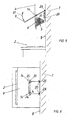
- Fig. 1 is a first embodiment of an extractor device according to the invention shown roughly schematically in the assembled state.
- the extractor hood this The embodiment is suitable for wall mounting and is designed as a chimney trained housing 4 arranged above a hob 2.
- the housing 4 has two suction areas 5, 6.
- the housing 4 the extractor device is in a manner known to those skilled in the art on a smooth and flat wall trained wall 7 set.
- the attachment points of the not shown Housing 4 on the wall 7 define a mounting level 8, with this Embodiment the mounting level 8 and the surface facing the housing 4 the wall 7 are identical.
- a vapor screen 9 is arranged, which is in the extends substantially transversely to the longitudinal axis, not shown in FIG.
- the side suction area is 6 by means of a closure device, not shown, and depending on the position of the Vapor umbrella 9 closable.
- the closure device can basically be manual be operable.
- the extractor device according to the invention also has a further below Adjustment device 10 described in more detail by means of which the position of the vapor shield 9 in a fixed setting range relative to the housing 4 is adjustable. This remains the edge of the vapor shield 9 facing the wall 7 essentially in one fixed distance to the mounting level 8 of the housing 4.
- the adjusting device 10 can be operated manually, namely by moving the vapor screen 9. Deviating from this embodiment it is also possible to transmit the adjusting device 10 with an electronic signal Control unit of the extractor device to connect and by means of an electrical Adjusting motor as a function of electrical signals from the electronic control unit to operate.
- the adjusting device 10 and thus the position of the Vapor screen 9 in this way depending on the output signal Proximity sensor can be moved or changed, so that a non-contact setting the location of the vapor screen 9 is made possible.
- the adjusting device 10 manually or automatically, directly or indirectly, it is possible to Adjustment device 10 and the closure device already explained mechanically with each other to connect, so that when changing the position of the vapor screen 9 the Closure device is actuated in the desired manner.
- FIG. 2 is a top view of the exemplary embodiment from FIG. 1.
- FIG. 2 clearly shows that the vapor shield 9 surrounds the housing 4 on three sides and that of the wall 7 facing edge with a small distance and essentially parallel to the mounting plane 8 runs. Furthermore, the edge of the vapor shield 9 facing the housing 4 runs in short distance and essentially parallel to the sides of the housing 4.
- a sealant designed as a sealing lip the edge of the vapor shield 9 facing the housing 4 can be arranged.
- the sealing lip is For example, made of an elastomeric material and to the edge of the Vapor umbrella 9 molded.
- FIG. 3 is a detailed view of the first exemplary embodiment from FIG. 1 in the area of FIG Adjustment device 10.
- the already explained longitudinal axis 12 of the housing 4 represented by a dash-dotted line.
- the vapor screen 9 shown in part is included solid lines shown in the first end position, in which the vapor shield 9 with its the user-facing end is lowered towards hob 2.
- the Vapor screen 9 shown with dashed lines in the second end position in which the Vapor screen 9 lowered with its end facing wall 7 in the direction of hob 2 is.
- the two end positions limit the setting range described above, in which the Vapor screen 9 can be adjusted relative to the housing 4 by means of the adjusting device 10.
- adjusting device 10 has an articulated guide 14 arranged on the housing 4 on.
- the articulated guide 14 contains a housing 4 facing and firmly connected to this first plate 16 and one on this first Plate 16 arranged second plate 18.
- the first plate 16 has a longitudinal groove trained first longitudinal guide 20, which is substantially in the direction of the longitudinal axis 12 extends.
- the second plate 18 is on the first plate 16 by a perpendicular to the Axial plane extending rotatably mounted and has an elongated hole 22 and a Bracket 24, in which is formed as a third bearing part and facing the housing 4 Edge of the vapor shield 9 in the assembled state in the longitudinal direction of the holder 24 is movably guided.
- a securing means through which the vapor shield 9 in each set position can be determined automatically.
- the peripheral surface of the first plate 16 facing the second plate 18 from one another spaced depressions arranged with the facing the first plate 16 Circumferential surface of the second plate 18 balls stored in a manner known to those skilled in the art interact as a rest system.
- Other known ones differ from this Latching systems as well as securing means that reduce the friction between the first and the second Use plates 16, 18, conceivable and that regardless of the facing surfaces of the two plates 16, 18.
- the adjusting device 10 of the above Embodiment has a spring means 28 formed as a spiral spring, which in the specified setting range of the vapor screen 9 on the second plate 18 a compressive force exercises.
- the spring means 28 is here in a receptacle arranged on the first plate 16 inserted. This makes it possible to position even heavy vapor screens 9, For example made of glass, with reasonable effort in both directions of rotation change.
- the vapor screen 9 of the invention arranged above the hob 2 Extractor hood device is in the first end position, so that the vapor screen 9 also whose end facing the user is lowered in the direction of the hob 2.
- the location of the vapor shield 9 guides the vapor shield 9 from the hob 2 Vapors in the direction of suction area 5, 6.
- the edge of the Vapor screen 9 runs essentially parallel and at a short distance from the Fastening level 8 of the housing 4, see Fig. 4.
- the spring means exercises 28 the greatest compressive force on the vapor screen 9, the compressive force of the spring means 28 in no position of the vapor shield 9 is greater than that by the securing means is transferable force.
- the second plate also rotates one perpendicular to the image plane extending axis and the first bearing part 26 is also in the first longitudinal guide 20 moved down towards hob 2.
- the directions of movement of the vapor screen 9 are symbolically indicated by double arrows 31.
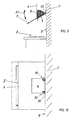
- FIG. 7 shows a third exemplary embodiment of the extractor hood device according to the invention shown.
- the second bearing part 34 is also a bolt educated.
- the user can Pressure against the end of the vapor screen 9 facing the user, the location of the Adjust fume screen 9.
- This embodiment also ensures that the Distance of the edge of the vapor shield 9 facing the wall 7 to the fastening plane 8 remains essentially the same. The same applies to the gap between the vapor shield 9 and the housing 4.
- the directions of movement of the vapor screen 9 are analogous to that previous exemplary embodiment symbolically indicated by double arrows 35.
- FIG. 10 shows a top view of the fourth exemplary embodiment from FIG. 9. This is from FIG. 10 hinge 36 designed as a holder is clearly visible.
- an extractor device allows adjustment of the vapor screen 9 to different body sizes. Further offer the mentioned embodiments the advantage that the distance between the Mounting level 8 of the housing 4 of the extractor device and in the Installation state of the wall 7 facing edge of the vapor screen 9 essentially the same remains.
- the first embodiment offers the advantage that the Adjustment device 10 is very compact and opposed by the second plate 18 Contamination, for example by rising vapors, is largely protected.
- the second embodiment offers the additional advantage that the lever arm between the Center of gravity of the vapor screen 9 and one of the bearing points, namely articulated guide 14 and third bearing part or first longitudinal guide 20 and first bearing part 26, due to the far apart bearings is low.
- the fourth embodiment has the additional advantage that it has only one bearing, namely joint 36, that is Number of components is reduced, and that it gives a visually pleasing impression.
Landscapes
- Engineering & Computer Science (AREA)
- Chemical & Material Sciences (AREA)
- Combustion & Propulsion (AREA)
- Mechanical Engineering (AREA)
- General Engineering & Computer Science (AREA)
- Physical Vapour Deposition (AREA)
- Apparatus For Radiation Diagnosis (AREA)
Applications Claiming Priority (2)
| Application Number | Priority Date | Filing Date | Title |
|---|---|---|---|
| DE10238904 | 2002-08-24 | ||
| DE2002138904 DE10238904B4 (de) | 2002-08-24 | 2002-08-24 | Dunstabzugsvorrichtung zur Anordnung über einem Arbeitsbereich, insbesondere Kochfeld |
Publications (1)
| Publication Number | Publication Date |
|---|---|
| EP1394473A2 true EP1394473A2 (fr) | 2004-03-03 |
Family
ID=31197342
Family Applications (1)
| Application Number | Title | Priority Date | Filing Date |
|---|---|---|---|
| EP20030017010 Withdrawn EP1394473A2 (fr) | 2002-08-24 | 2003-07-26 | Hotte d'aspiration à placer au-dessus d'une zône de travail, en particulier un plan de cuisson |
Country Status (2)
| Country | Link |
|---|---|
| EP (1) | EP1394473A2 (fr) |
| DE (1) | DE10238904B4 (fr) |
Cited By (2)
| Publication number | Priority date | Publication date | Assignee | Title |
|---|---|---|---|---|
| WO2008055837A3 (fr) * | 2006-11-10 | 2008-09-25 | Bsh Bosch Siemens Hausgeraete | Hotte |
| CN102032611A (zh) * | 2011-01-06 | 2011-04-27 | 吴小国 | 半圆型防护式吸油烟机 |
Families Citing this family (1)
| Publication number | Priority date | Publication date | Assignee | Title |
|---|---|---|---|---|
| DE102006005806A1 (de) * | 2006-02-08 | 2007-08-16 | BSH Bosch und Siemens Hausgeräte GmbH | Dunstabzugsvorrichtung |
Citations (1)
| Publication number | Priority date | Publication date | Assignee | Title |
|---|---|---|---|---|
| DE7433594U (de) | 1975-01-09 | Imperial Werke Gmbh | Küchen-Oberschrank mit eingebauter Dunstabzugshaube |
Family Cites Families (2)
| Publication number | Priority date | Publication date | Assignee | Title |
|---|---|---|---|---|
| DE8023368U1 (de) * | 1980-09-02 | 1983-12-08 | Bosch-Siemens Hausgeräte GmbH, 7000 Stuttgart | Dunstabzugshaube |
| DE20005733U1 (de) * | 2000-03-28 | 2000-08-10 | Homeier, Max, 93057 Regensburg | Dunstabzugshaube |
-
2002
- 2002-08-24 DE DE2002138904 patent/DE10238904B4/de not_active Expired - Fee Related
-
2003
- 2003-07-26 EP EP20030017010 patent/EP1394473A2/fr not_active Withdrawn
Patent Citations (1)
| Publication number | Priority date | Publication date | Assignee | Title |
|---|---|---|---|---|
| DE7433594U (de) | 1975-01-09 | Imperial Werke Gmbh | Küchen-Oberschrank mit eingebauter Dunstabzugshaube |
Cited By (4)
| Publication number | Priority date | Publication date | Assignee | Title |
|---|---|---|---|---|
| WO2008055837A3 (fr) * | 2006-11-10 | 2008-09-25 | Bsh Bosch Siemens Hausgeraete | Hotte |
| CN101535724A (zh) * | 2006-11-10 | 2009-09-16 | Bsh博施及西门子家用器具有限公司 | 烟雾排除罩 |
| US8757141B2 (en) | 2006-11-10 | 2014-06-24 | Bsh Bosch Und Siemens Hausgeraete Gmbh | Extractor hood |
| CN102032611A (zh) * | 2011-01-06 | 2011-04-27 | 吴小国 | 半圆型防护式吸油烟机 |
Also Published As
| Publication number | Publication date |
|---|---|
| DE10238904B4 (de) | 2008-05-29 |
| DE10238904A1 (de) | 2004-03-04 |
Similar Documents
| Publication | Publication Date | Title |
|---|---|---|
| EP3452681B1 (fr) | Dispositif d'étanchéité pour une porte couilissante | |
| EP1296011B1 (fr) | Couvercle pliant à deux panneaux | |
| EP3973126B1 (fr) | Ferrure de meuble | |
| EP3452680B1 (fr) | Dispositif d'étanchéité | |
| EP2096360B1 (fr) | Porte d'appareil ménager | |
| EP4086418B1 (fr) | Système comprenant un meuble doté d'une niche intégrée et d'un appareil intégré, et procédé de fonctionnement du système | |
| DE102005007042A1 (de) | Öffnungs- und Schließmechanismus für einen Deckel | |
| EP3973130A1 (fr) | Ferrure pour meuble | |
| DE4220668C1 (de) | Betätigungsvorrichtung für eine Stellklappe in Kraftfahrzeugen | |
| AT17215U1 (de) | Möbelbeschlag | |
| WO1999036654A1 (fr) | Systeme de fermeture a barre coulissante | |
| EP1907657A1 (fr) | Element d'amortissement | |
| EP3341673B1 (fr) | Dispositif de levage/pivotement pour un couvercle de trou d'homme d'un véhicule protégé, ensemble couvercle de trou d'homme et véhicule protégé | |
| EP0347537B1 (fr) | Portière avec cadre de vitre | |
| EP3623559B1 (fr) | Ferrure de couvercle destinée à la fixation pivotante d'un couvercle de meuble à un corps de meuble | |
| DE10238904B4 (de) | Dunstabzugsvorrichtung zur Anordnung über einem Arbeitsbereich, insbesondere Kochfeld | |
| DE202019102261U1 (de) | Tür mit einem beweglichen Dichtungselement und HF-Schirmungskabine | |
| DE10250905A1 (de) | Verstelleinrichtung für ein Lenkrad eines Flurförderzeugs | |
| EP2089660A2 (fr) | Hotte | |
| DE19928194B4 (de) | Bewegungsdämpferanordnung mit integriertem Tastschalter insbesondere für Kraftfahrzeuge | |
| DE102006015757B4 (de) | Becherhalter für ein Kraftfahrzeug | |
| EP2388169B1 (fr) | Dispositif d'actionnement pour un frein de stationnement | |
| DE19510859C1 (de) | Abluftdrossel | |
| DE102005029452A1 (de) | Getriebe für einen Panikgriff oder eine Panikstange | |
| EP1907658A1 (fr) | Mecanisme d'amortissement |
Legal Events
| Date | Code | Title | Description |
|---|---|---|---|
| PUAI | Public reference made under article 153(3) epc to a published international application that has entered the european phase |
Free format text: ORIGINAL CODE: 0009012 |
|
| AK | Designated contracting states |
Kind code of ref document: A2 Designated state(s): AT BE BG CH CY CZ DE DK EE ES FI FR GB GR HU IE IT LI LU MC NL PT RO SE SI SK TR |
|
| AX | Request for extension of the european patent |
Extension state: AL LT LV MK |
|
| STAA | Information on the status of an ep patent application or granted ep patent |
Free format text: STATUS: THE APPLICATION IS DEEMED TO BE WITHDRAWN |
|
| 18D | Application deemed to be withdrawn |
Effective date: 20060201 |