EP1394563B1 - Etalonnage en ligne d'un réseau d'antennes à commande de phase - Google Patents
Etalonnage en ligne d'un réseau d'antennes à commande de phase Download PDFInfo
- Publication number
- EP1394563B1 EP1394563B1 EP20030013029 EP03013029A EP1394563B1 EP 1394563 B1 EP1394563 B1 EP 1394563B1 EP 20030013029 EP20030013029 EP 20030013029 EP 03013029 A EP03013029 A EP 03013029A EP 1394563 B1 EP1394563 B1 EP 1394563B1
- Authority
- EP
- European Patent Office
- Prior art keywords
- calibration
- antenna element
- start pulse
- phase
- receiving antenna
- Prior art date
- Legal status (The legal status is an assumption and is not a legal conclusion. Google has not performed a legal analysis and makes no representation as to the accuracy of the status listed.)
- Expired - Lifetime
Links
- 238000000034 method Methods 0.000 claims description 24
- 230000010355 oscillation Effects 0.000 claims description 13
- 230000005540 biological transmission Effects 0.000 claims description 8
- 239000011159 matrix material Substances 0.000 claims description 7
- 238000011156 evaluation Methods 0.000 claims description 4
- 238000012937 correction Methods 0.000 claims description 3
- 238000001514 detection method Methods 0.000 claims 3
- 230000008878 coupling Effects 0.000 description 6
- 238000010168 coupling process Methods 0.000 description 6
- 238000005859 coupling reaction Methods 0.000 description 6
- 238000012545 processing Methods 0.000 description 5
- 230000032683 aging Effects 0.000 description 3
- 238000010586 diagram Methods 0.000 description 3
- 238000006243 chemical reaction Methods 0.000 description 2
- 230000007613 environmental effect Effects 0.000 description 2
- 230000005855 radiation Effects 0.000 description 2
- 230000001960 triggered effect Effects 0.000 description 2
- 230000015556 catabolic process Effects 0.000 description 1
- 238000006731 degradation reaction Methods 0.000 description 1
- 238000011161 development Methods 0.000 description 1
- 230000018109 developmental process Effects 0.000 description 1
- 238000005516 engineering process Methods 0.000 description 1
- 238000001914 filtration Methods 0.000 description 1
- 238000005259 measurement Methods 0.000 description 1
- 239000000758 substrate Substances 0.000 description 1
- 230000002277 temperature effect Effects 0.000 description 1
Images


Classifications
-
- G—PHYSICS
- G01—MEASURING; TESTING
- G01S—RADIO DIRECTION-FINDING; RADIO NAVIGATION; DETERMINING DISTANCE OR VELOCITY BY USE OF RADIO WAVES; LOCATING OR PRESENCE-DETECTING BY USE OF THE REFLECTION OR RERADIATION OF RADIO WAVES; ANALOGOUS ARRANGEMENTS USING OTHER WAVES
- G01S7/00—Details of systems according to groups G01S13/00, G01S15/00, G01S17/00
- G01S7/02—Details of systems according to groups G01S13/00, G01S15/00, G01S17/00 of systems according to group G01S13/00
- G01S7/40—Means for monitoring or calibrating
- G01S7/4004—Means for monitoring or calibrating of parts of a radar system
- G01S7/4026—Antenna boresight
-
- H—ELECTRICITY
- H01—ELECTRIC ELEMENTS
- H01Q—ANTENNAS, i.e. RADIO AERIALS
- H01Q21/00—Antenna arrays or systems
-
- H—ELECTRICITY
- H01—ELECTRIC ELEMENTS
- H01Q—ANTENNAS, i.e. RADIO AERIALS
- H01Q23/00—Antennas with active circuits or circuit elements integrated within them or attached to them
-
- H—ELECTRICITY
- H01—ELECTRIC ELEMENTS
- H01Q—ANTENNAS, i.e. RADIO AERIALS
- H01Q3/00—Arrangements for changing or varying the orientation or the shape of the directional pattern of the waves radiated from an antenna or antenna system
- H01Q3/26—Arrangements for changing or varying the orientation or the shape of the directional pattern of the waves radiated from an antenna or antenna system varying the relative phase or relative amplitude of energisation between two or more active radiating elements; varying the distribution of energy across a radiating aperture
- H01Q3/267—Phased-array testing or checking devices
-
- G—PHYSICS
- G01—MEASURING; TESTING
- G01S—RADIO DIRECTION-FINDING; RADIO NAVIGATION; DETERMINING DISTANCE OR VELOCITY BY USE OF RADIO WAVES; LOCATING OR PRESENCE-DETECTING BY USE OF THE REFLECTION OR RERADIATION OF RADIO WAVES; ANALOGOUS ARRANGEMENTS USING OTHER WAVES
- G01S13/00—Systems using the reflection or reradiation of radio waves, e.g. radar systems; Analogous systems using reflection or reradiation of waves whose nature or wavelength is irrelevant or unspecified
- G01S13/02—Systems using reflection of radio waves, e.g. primary radar systems; Analogous systems
- G01S2013/0236—Special technical features
- G01S2013/0245—Radar with phased array antenna
Definitions
- the invention is based on a method for calibrating a group antenna with a transmitting antenna and a plurality of receiving antenna elements of a pulse echo radar system.
- system-immanent signal forms of the radar radiation used in accordance with the invention are utilized in the form of their start pulse for the online calibration of an individual path and the individual paths to one another.
- a trigger circuit ensures the necessary timely exact transmission of the wave packet of the radar pulse.
- the starting pulse for the online calibration can be used in such a way that it is preferably recorded in all receiving channels of the group antenna.
- Fig. 1 is the representation of a time signal of an inventively equipped pulse echo radar system with a group antenna which is calibrated according to the invention without a reference target with a known position, the y-axis indicating its amplitude in volts, the x-axis indicates a distance in meters as they pass through Conversion results from the running time of the signal.
- Fig. 1 detailing the time signal as recorded in a single (of several) receive element paths.
- the signal depicted by reference numeral 10 is the in-phase component of the start pulse used in accordance with the invention, as recorded in a receive antenna element of the array antenna.
- the peak 12 of its in-phase component I can be seen, which corresponds to the starting pulse itself.
- the quadrature phase component Q of the start pulse, as recorded in the same receive antenna element, is designated by reference numeral 14.
- the peak 16 corresponding to the starting pulse of this component Q is significantly lower in amplitude. Due to differences in the amplitude of the two peaks According to the invention, an amplitude mismatch between the two components I and Q of the single path can be detected and digitally corrected, as will be described below.
- Fig. 2 shows a schematic diagram of a sensor structure according to the invention, in which the calibration method according to the invention can be successfully applied.
- a radiating element 20 is provided.
- the array antenna has a plurality of receiving elements 22, 23, 24, 25, which have a respective receiving branch 26, 27, 28, 29, the above signals, namely in-phase component I and quadrature phase component Q for further processing of the signals according to the Technique in each provided for I and Q separately provided low-pass filter 30 (LP) and an analog / digital converter component 32 (ADC) continues.
- the latter components 30 and 32 are provided for each of the reception branches 26 to 29, but shown for the sake of clarity only for a branch.
- a digital signal processor 34 is connected to each of the receiving branches and carries out a multi-channel signal processing, whereby the recalibration according to the invention itself is performed.
- the angle information for determining the The direction of arrival of various signals at the receiving antenna elements 22 to 25 is obtained from the phase information of the individual, incoming signals.
- the phase information itself is obtained from the amplitude comparison of the in-phase and quadrature-phase components of the incoming signal. A falsification of the amplitudes due to the above-mentioned aging, temperature and other environmental influences thus inevitably leads to a distortion of the phase information.
- the transmitting antenna element indicated by reference numeral 20 represents the radiating device Fig. 2 illustrated receiving elements 22 to 25 an array, preferably the same plurality, for example 4, of regularly linearly arranged individual receiving elements. Such an arrangement is known in the art.
- the individual antenna elements of the receiving array 22 to 25 are arranged at a distance of half a wavelength of the carrier frequency of, for example, 24 gigahertz to each other.
- the transmitting antenna 20 is advantageously arranged at a predefined distance from the first receiving antenna element 22, the distance also advantageously corresponding to half the wavelength of the carrier frequency.
- half the wavelength can be selected as a distance and an integer multiple n of it, as shown.
- other distances can be selected, which then each specific sequence changes in the other Course of the calibration process and are known in the art.
- a radar wave packet should now always be started according to the invention at time T / 8 of the carrier oscillation, where T corresponds to the carrier oscillation time. Then, an input signal is produced at all receiving elements whose in-phase component I and quadrature-phase component Q have amplitudes which are ideally equal. In this ideal case, recalibration according to the invention would not be necessary. A deviation of the amplitudes of I and Q of the start pulse from a reference value that matches the phase offset can thus be detected and corrected.
- a deviation of the amplitude quantities from one another is readily detectable from the influences mentioned at the outset by means of methods known in the prior art - low-pass filtering, A / D conversion and digital signal processing.
- This deviation is now individually different for each signal path, depending on the aging and other influences occurring in the signal path.
- one component, or both (I, Q) can now be changed such that both amplitudes are the same size, that is to say they have essentially the same digital values.
- Analogous to Fig. 1 would the digital data be the two amplitudes in Fig. 1 be corrected so that the amplitudes appear equal. If the digital values corresponding to the amplitudes are corrected, the further processing of the values for the actual intended use known in the prior art can be carried out.
- the digital correction can be done for example by multiplication with an individual factor.
- An essential prerequisite for a successful online calibration according to the invention is that the start pulse of the wave packet is triggered at an exact, predefined time. This time is in relation to the phase characteristic of the carrier signal and can be achieved for example by triggering the Pulsradartaktpulses by the carrier vibration itself.
- the antenna elements are arranged in multiples of half the wavelength of the carrier frequency, it should advantageously be ensured that the wave packet is always transmitted at the time of T / 8 of the carrier oscillation. At other geometrical intervals, correspondingly different triggering times result in the carrier signal.
- a sine wave generator 40 sends a sine wave both in the transmit path 21 and via a signal path 42 to the receive branches 26 to 29.
- a switch 44 in the transmit branch 21 is triggered by a rectangular pulse, shown by reference numeral 46. This is done with a preselected pulse repetition frequency.
- a trigger circuit 48 is provided which ensures that, at the transmitting antenna element 20, after a zero crossing of the carrier oscillation, the starting pulse is always transmitted in the phase state 45 ° (T / 8).
- the trigger circuit can be controlled, for example, by a frequency divider circuit. alternative and in a preferred manner also zero crossings in the 24 GHz carrier signal can be detected, taking into account the time of opening of the switch 44 by the geometry and in particular the transit time for the signal in the transmitting branch, so that when the carrier signal has a zero crossing, the start pulse in the phase state of 45 ° (T / 8) is sent.
- a delay circuit 52 is shown connected to a switch 54 which ensures that the receiving elements 22 to 25 are switched on with a time offset matching the geometrical distance between the transmitting element 20 and the respective receiving element 22 to 25 so that the starting pulse can be received as intended.
- the set delay thus corresponds exactly to the transit time of the radar signal between the transmitting antenna element and a respective receiving element 22 to 25.
- the aforementioned circuit is now active in the above-mentioned sense according to a preselected pulse repetition frequency, so that not a single pulse is evaluated, but, as usual in the prior art, a signal accumulated over a preselected plurality of pulses is received for evaluation.
- the abovementioned triggering is also necessary for most radar sensors known in the state of the art because the frequency of the carrier oscillation changes constantly due to load changes at the oscillator output and due to temperature effects.
- the high-frequency carrier signal can be divided by integer numbers, for example by a factor of 100, by means of corresponding components known in the prior art.
- the resulting, low-frequency signal is then preferably detects a zero crossing and used as a trigger point for triggering the switching pulse, as mentioned above.
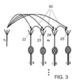
- the method according to the invention is also suitable for the calibration of the amplitude and phase errors between the individual element paths of the array antenna, as follows with additional reference to Fig. 3 is described.
- the couplings between the individual elements of the array antenna are time-invariant and thus were recorded in the offline factory calibration mentioned above. They are stored in a memory area of the group antenna in the form of the so-called offline calibration matrix.
- the amplitude and phase relationships are precisely determined, resulting in the transmission of the start pulse and the direct propagation through the air or through the substrate of the array on the receiving elements 22 to 25.
- the direct coupling between the individual receiving elements is in FIG. 3 schematically represented by the double arrows 60.
- the inventive method for online calibration between the single element paths preferably contains the following steps, which in the Fig. 2 described circuit elements 30, 32, 34 are performed:
- the start pulse is picked up on all the antenna elements 22 to 25. Then, the start pulse signal is multiplied by the offline calibration matrix according to the signal propagation ratios between the transmit antenna and the respective receive antenna element, as known from offline calibration, to check the validity of the calibration. If the calibration is still valid, the unit matrix results. Have the propagation conditions regarding amplitude u. Phase changed, i. the calibration is no longer valid, an error vector results. The error vector is finally inverted and the old calibration matrix is multiplied by the inverted error vector. This results in the new calibration matrix which compensates for the errors between the single element paths 22-25.
- an arbitrarily repeatable online calibration of amplitude errors between the phase components I and Q as well as amplitude and phase errors between the individual channels of a group antenna according to the invention can be carried out without additionally existing reference targets with a fixed location specification relative to the array antenna.
- the method according to the invention utilizes existing physical conditions in the form of the start pulse in the system anyway.
- computer resources of the digital signal processor 34 in the pulse echo radar system which are present anyway, can be exploited, for example, to perform a recalibration of the array antenna at regular intervals. The reliability and accuracy of the pulse echo radar system is thereby significantly increased.
- the parameters T / 8, n, ⁇ / 2 can each be suitably varied.
- the method according to the invention can also be used in a time-duplex-capable array antenna in which the transmission antenna elements are a subset of the reception elements and are alternately transmitted and received.
- a calibration of the reception paths in time-division duplex systems is possible. For this purpose, it must be ensured that in the calibration mode, an intelligent element drive ensures that a transmitting element is not a receiving element at the same time.
Landscapes
- Engineering & Computer Science (AREA)
- Radar, Positioning & Navigation (AREA)
- Remote Sensing (AREA)
- Computer Networks & Wireless Communication (AREA)
- Physics & Mathematics (AREA)
- General Physics & Mathematics (AREA)
- Radar Systems Or Details Thereof (AREA)
Claims (6)
- Procédé d'étalonnage d'une antenne groupée qui présente un élément (20) d'antenne d'émission et plusieurs éléments (22, 23, 24, 25) d'antenne de réception dans un système radar à écho pulsé, qui comporte l'étape qui consiste à utiliser comme signal de référence dans les éléments (22, 23, 24, 25) d'antenne de réception une impulsion (10, 14) ajoutée directement par l'élément (20) d'antenne d'émission pour étalonner en ligne les erreurs d'amplitude et phase de l'antenne groupée,
caractérisé en ce que
l'impulsion est une impulsion de démarrage et
en ce que pour l'étalonnage du désaccord d'amplitude entre la composante en phase I et la composante en quadrature de phase Q du parcours (26, 27, 28, 29) d'un élément individuel de l'antenne groupée, les étapes suivantes sont exécutées :a) émission de l'impulsion de démarrage (10, 14) définie temporellement avec un déphasage prédéterminé par rapport à l'évolution de la phase de l'onde porteuse de l'impulsion de démarrage,b) détection de différence d'amplitude entre le I et le Q de l'impulsion de démarrage par rapport à une valeur de référence adaptée au déphasage prédéterminé etc) correction numérique de la différence dans une logique d'évaluation (30, 32, 34) de l'antenne groupée, raccordée en aval de l'élément d'antenne de réception du parcours individuel. - Procédé selon la revendication 1 qui précède, caractérisé en ce que le déphasage de l'oscillation porteuse est de 45°, en ce que l'élément (20) d'antenne d'émission est disposé à une distance qui correspond à un multiple entier n d'une demi-longueur d'onde de l'oscillation porteuse par rapport à l'élément (22) suivant d'antenne de réception et en ce que les éléments (22, 23, 24, 25) d'antenne de réception sont également disposés à une distance qui correspond à un multiple n entier d'une demi-longueur d'onde de l'oscillation porteuse.
- Procédé selon la revendication 2 qui précède, caractérisé en ce que l'émission de l'impulsion de démarrage s'effectue à l'aide d'un dispositif d'activation (46, 48) qui répond au passage par zéro de l'évolution du signal de l'oscillation porteuse.
- Procédé selon la revendication 3 qui précède, caractérisé en ce que l'activation de l'instant d'émission repose sur une division en fréquence et ensuite sur la détection du passage par zéro du signal porteur.
- Procédé selon la revendication 1, caractérisé en ce que pour l'étalonnage en ligne des erreurs d'amplitude et de phase entre les différents parcours (26, 27, 28, 29) des éléments d'antenne de réception de l'antenne groupée, les étapes suivantes sont exécutées:a) réception du signal (10, 14) de l'impulsion de démarrage par les différents éléments (22, 23, 24, 25) d'antenne de réception,b) multiplication du signal (10, 14) de l'impulsion de démarrage en fonction des conditions de propagation du signal, connues à partir d'un étalonnage en ligne, entre l'élément (20) d'antenne d'émission et chaque élément (22, 23, 24, 25) d'antenne de réception, ce qui donne un vecteur d'erreur etc) mise à jour de la matrice d'étalonnage en ligne par multiplication de la matrice par l'inverse du vecteur d'erreur.
- Système radar à écho pulsé doté de dispositifs en vue de l'exécution du procédé d'étalonnage selon l'une des revendications précédentes, les dispositifs comprenant :une antenne groupée qui présente un élément (20) d'antenne d'émission et plusieurs éléments (22, 23, 24, 25) d'antenne de réception,un générateur (40) qui crée une oscillation porteuse,un dispositif d'activation (46, 48) qui répond aux passages par zéro de l'évolution du signal de l'oscillation porteuse et qui active un commutateur (44) disposé dans la branche d'émission (21) de telle sorte que l'élément (20) d'antenne d'émission émette une impulsion de démarrage à un déphasage prédéterminé par rapport à l'évolution de la phase de l'oscillation porteuse etune logique d'évaluation (30, 32, 34) raccordée en aval de chaque élément (22, 23, 24, 25) d'antenne de réception pour détecter une différence d'amplitude entre la composante en phase et la composante en quadrature de phase de l'impulsion de démarrage par rapport à une valeur de référence adaptée au déphasage prédéterminé, et pour corriger numériquement la différence.
Applications Claiming Priority (2)
| Application Number | Priority Date | Filing Date | Title |
|---|---|---|---|
| DE10238213 | 2002-08-21 | ||
| DE2002138213 DE10238213A1 (de) | 2002-08-21 | 2002-08-21 | Online Kalibrierung eines Radarsensors mit Gruppenantenne |
Publications (2)
| Publication Number | Publication Date |
|---|---|
| EP1394563A1 EP1394563A1 (fr) | 2004-03-03 |
| EP1394563B1 true EP1394563B1 (fr) | 2009-06-10 |
Family
ID=31197162
Family Applications (1)
| Application Number | Title | Priority Date | Filing Date |
|---|---|---|---|
| EP20030013029 Expired - Lifetime EP1394563B1 (fr) | 2002-08-21 | 2003-06-10 | Etalonnage en ligne d'un réseau d'antennes à commande de phase |
Country Status (2)
| Country | Link |
|---|---|
| EP (1) | EP1394563B1 (fr) |
| DE (2) | DE10238213A1 (fr) |
Cited By (1)
| Publication number | Priority date | Publication date | Assignee | Title |
|---|---|---|---|---|
| RU2486540C1 (ru) * | 2011-12-05 | 2013-06-27 | Открытое Акционерное Общество "Уральское проектно-конструкторское бюро "Деталь" | Имитатор ложной радиолокационной цели при зондировании сигналами с линейной частотной модуляцией |
Families Citing this family (8)
| Publication number | Priority date | Publication date | Assignee | Title |
|---|---|---|---|---|
| US7522096B2 (en) | 2007-04-09 | 2009-04-21 | Honeywell International Inc | Method for phase calibrating antennas in a radar system |
| CN108267723A (zh) * | 2017-01-04 | 2018-07-10 | 南京智慧魔方电子科技有限公司 | 陆基短距k波段雷达的离线在线式幅相误差校正方法 |
| CN110531329B (zh) * | 2019-09-25 | 2023-06-27 | 中南大学 | 一种用于冲激脉冲式穿墙雷达的多通道误差自校正方法 |
| KR102883635B1 (ko) * | 2019-10-11 | 2025-11-07 | 레오랩스, 인크. | 레이더 보정 및 우주 물체 추적 |
| CN111123220B (zh) * | 2019-11-29 | 2023-11-07 | 瞬联软件科技(北京)有限公司 | 一种毫米波雷达的多通道幅相校准方法及系统 |
| CN113504518B (zh) * | 2021-07-08 | 2023-06-20 | 南京俊东机电设备有限公司 | 一种相控阵电子装备外场标校方法 |
| WO2024209760A1 (fr) * | 2023-04-06 | 2024-10-10 | 株式会社村田製作所 | Dispositif d'estimation de direction d'arrivée et procédé d'estimation de direction d'arrivée |
| CN118091563B (zh) * | 2024-02-28 | 2024-09-24 | 中国舰船研究设计中心 | 一种面向分布式可移动电磁脉冲空间发射相参合成方法 |
Family Cites Families (3)
| Publication number | Priority date | Publication date | Assignee | Title |
|---|---|---|---|---|
| GB2289799B (en) * | 1991-09-17 | 1996-04-17 | Cossor Electronics Ltd | Improvements relating to radar antenna systems |
| US5682165A (en) * | 1996-05-02 | 1997-10-28 | Hughes Electronics | Active array self calibration |
| DE19941473A1 (de) * | 1998-09-04 | 2000-03-09 | Bosch Gmbh Robert | Verfahren und Vorrichtung zur Selbstkalibrierung von Gruppenantennen |
-
2002
- 2002-08-21 DE DE2002138213 patent/DE10238213A1/de not_active Withdrawn
-
2003
- 2003-06-10 EP EP20030013029 patent/EP1394563B1/fr not_active Expired - Lifetime
- 2003-06-10 DE DE50311583T patent/DE50311583D1/de not_active Expired - Lifetime
Cited By (1)
| Publication number | Priority date | Publication date | Assignee | Title |
|---|---|---|---|---|
| RU2486540C1 (ru) * | 2011-12-05 | 2013-06-27 | Открытое Акционерное Общество "Уральское проектно-конструкторское бюро "Деталь" | Имитатор ложной радиолокационной цели при зондировании сигналами с линейной частотной модуляцией |
Also Published As
| Publication number | Publication date |
|---|---|
| DE50311583D1 (de) | 2009-07-23 |
| EP1394563A1 (fr) | 2004-03-03 |
| DE10238213A1 (de) | 2004-03-04 |
Similar Documents
| Publication | Publication Date | Title |
|---|---|---|
| EP3467450B1 (fr) | Appareil de mesure de niveau de remplissage à radar pourvu d'un système radar sur puce | |
| EP0535196B1 (fr) | Procede et dispositif pour la mesure de distance selon le principe de la retroreflection | |
| EP2783237B1 (fr) | Appareil radar et procédé pour détecter une panne d'un canal de réception d'un appareil radar | |
| EP1185881B1 (fr) | Dispositif telemetrique et procede pour le calibrage d'un dispositif telemetrique | |
| DE102008050329A1 (de) | Mit Mikrowellen arbeitendes Füllstandsmessgerät | |
| EP1261501B1 (fr) | Produit comprenant un capteur et un element a ondes de surface, ainsi que procede et systeme pour determiner une grandeur de mesure d'un capteur correspondant a une resistance reactive | |
| DE102018207718A1 (de) | Verfahren zur Phasenkalibrierung von Hochfrequenzbausteinen eines Radarsensors | |
| EP0829710A2 (fr) | Capteur de pression utilisant des éléments à ondes acoustiques de surface | |
| EP1394563B1 (fr) | Etalonnage en ligne d'un réseau d'antennes à commande de phase | |
| EP1325289A1 (fr) | Appareil pour mesurer un niveau de remplissage | |
| DE102007020045A1 (de) | Radarsystem und Verunreinigungsbeurteilungsverfahren | |
| EP1210567A1 (fr) | Dispositif permettant de determiner une grandeur physique relative a un milieu | |
| DE102018217110A1 (de) | Radarsystem, sowie eine geeignete Verwendung und Verfahren hierfür | |
| DE10027064A1 (de) | Doppler-Impulsradarsystem | |
| DE2153432B2 (de) | Akustischer Durchflußmesser | |
| DE10018552A1 (de) | Verfahren zur Erfassung und Korrektur von Nichtlinearitäten in einem Mikrowellenradarsystem | |
| DE102017100269A1 (de) | Verfahren zur Detektion eines Fehlerzustandes an einem FMCW-basierten Füllstandsmessgerät | |
| WO2019149513A1 (fr) | Procédé de détection d'états d'erreur potentiels sur un dispositif de mesure de remplissage à base de fmcw | |
| EP1481230B1 (fr) | Procede et dispositif pour le mesurage et le calibrage de capteurs a ondes acoustiques de surface (saw) | |
| DE102010040890A1 (de) | Radarsensor mit phasengeregeltem Oszillator | |
| DE19622154A1 (de) | Elektroakustisches Bauelement und Verfahren zur Fernidentifikation | |
| DE102006041827B4 (de) | Verfahren zur Bestimmung eines Zeitintervalls | |
| DE19527325A1 (de) | Linearisierung von Wobblersystemen | |
| EP4232783B1 (fr) | Appareil de mesure de niveau de détection de topologie | |
| EP0815469A1 (fr) | Procede pour effectuer une interrogation a distance sans contact |
Legal Events
| Date | Code | Title | Description |
|---|---|---|---|
| PUAI | Public reference made under article 153(3) epc to a published international application that has entered the european phase |
Free format text: ORIGINAL CODE: 0009012 |
|
| AK | Designated contracting states |
Kind code of ref document: A1 Designated state(s): AT BE BG CH CY CZ DE DK EE ES FI FR GB GR HU IE IT LI LU MC NL PT RO SE SI SK TR |
|
| AX | Request for extension of the european patent |
Extension state: AL LT LV MK |
|
| 17P | Request for examination filed |
Effective date: 20040903 |
|
| AKX | Designation fees paid |
Designated state(s): DE ES FR GB IT SE |
|
| 17Q | First examination report despatched |
Effective date: 20070202 |
|
| GRAP | Despatch of communication of intention to grant a patent |
Free format text: ORIGINAL CODE: EPIDOSNIGR1 |
|
| RIC1 | Information provided on ipc code assigned before grant |
Ipc: H01Q 3/26 20060101AFI20090220BHEP |
|
| GRAS | Grant fee paid |
Free format text: ORIGINAL CODE: EPIDOSNIGR3 |
|
| GRAA | (expected) grant |
Free format text: ORIGINAL CODE: 0009210 |
|
| AK | Designated contracting states |
Kind code of ref document: B1 Designated state(s): DE ES FR GB IT SE |
|
| REG | Reference to a national code |
Ref country code: GB Ref legal event code: FG4D Free format text: NOT ENGLISH |
|
| REF | Corresponds to: |
Ref document number: 50311583 Country of ref document: DE Date of ref document: 20090723 Kind code of ref document: P |
|
| PG25 | Lapsed in a contracting state [announced via postgrant information from national office to epo] |
Ref country code: SE Free format text: LAPSE BECAUSE OF FAILURE TO SUBMIT A TRANSLATION OF THE DESCRIPTION OR TO PAY THE FEE WITHIN THE PRESCRIBED TIME-LIMIT Effective date: 20090910 |
|
| PG25 | Lapsed in a contracting state [announced via postgrant information from national office to epo] |
Ref country code: ES Free format text: LAPSE BECAUSE OF FAILURE TO SUBMIT A TRANSLATION OF THE DESCRIPTION OR TO PAY THE FEE WITHIN THE PRESCRIBED TIME-LIMIT Effective date: 20090921 |
|
| PLBE | No opposition filed within time limit |
Free format text: ORIGINAL CODE: 0009261 |
|
| STAA | Information on the status of an ep patent application or granted ep patent |
Free format text: STATUS: NO OPPOSITION FILED WITHIN TIME LIMIT |
|
| 26N | No opposition filed |
Effective date: 20100311 |
|
| PG25 | Lapsed in a contracting state [announced via postgrant information from national office to epo] |
Ref country code: IT Free format text: LAPSE BECAUSE OF FAILURE TO SUBMIT A TRANSLATION OF THE DESCRIPTION OR TO PAY THE FEE WITHIN THE PRESCRIBED TIME-LIMIT Effective date: 20090610 |
|
| REG | Reference to a national code |
Ref country code: FR Ref legal event code: PLFP Year of fee payment: 13 |
|
| PGFP | Annual fee paid to national office [announced via postgrant information from national office to epo] |
Ref country code: GB Payment date: 20150623 Year of fee payment: 13 |
|
| PGFP | Annual fee paid to national office [announced via postgrant information from national office to epo] |
Ref country code: FR Payment date: 20150623 Year of fee payment: 13 |
|
| GBPC | Gb: european patent ceased through non-payment of renewal fee |
Effective date: 20160610 |
|
| REG | Reference to a national code |
Ref country code: FR Ref legal event code: ST Effective date: 20170228 |
|
| PG25 | Lapsed in a contracting state [announced via postgrant information from national office to epo] |
Ref country code: FR Free format text: LAPSE BECAUSE OF NON-PAYMENT OF DUE FEES Effective date: 20160630 |
|
| PG25 | Lapsed in a contracting state [announced via postgrant information from national office to epo] |
Ref country code: GB Free format text: LAPSE BECAUSE OF NON-PAYMENT OF DUE FEES Effective date: 20160610 |
|
| PGFP | Annual fee paid to national office [announced via postgrant information from national office to epo] |
Ref country code: DE Payment date: 20170809 Year of fee payment: 15 |
|
| REG | Reference to a national code |
Ref country code: DE Ref legal event code: R119 Ref document number: 50311583 Country of ref document: DE |
|
| PG25 | Lapsed in a contracting state [announced via postgrant information from national office to epo] |
Ref country code: DE Free format text: LAPSE BECAUSE OF NON-PAYMENT OF DUE FEES Effective date: 20190101 |