EP1394820A2 - Weichmagnetischer Werkstoff und und Verfahren zur Herstellung - Google Patents
Weichmagnetischer Werkstoff und und Verfahren zur Herstellung Download PDFInfo
- Publication number
- EP1394820A2 EP1394820A2 EP03019759A EP03019759A EP1394820A2 EP 1394820 A2 EP1394820 A2 EP 1394820A2 EP 03019759 A EP03019759 A EP 03019759A EP 03019759 A EP03019759 A EP 03019759A EP 1394820 A2 EP1394820 A2 EP 1394820A2
- Authority
- EP
- European Patent Office
- Prior art keywords
- powder
- dispersion
- magnetic
- frequency
- loss material
- Prior art date
- Legal status (The legal status is an assumption and is not a legal conclusion. Google has not performed a legal analysis and makes no representation as to the accuracy of the status listed.)
- Withdrawn
Links
Images





Classifications
-
- H—ELECTRICITY
- H01—ELECTRIC ELEMENTS
- H01F—MAGNETS; INDUCTANCES; TRANSFORMERS; SELECTION OF MATERIALS FOR THEIR MAGNETIC PROPERTIES
- H01F10/00—Thin magnetic films, e.g. of one-domain structure
-
- H—ELECTRICITY
- H05—ELECTRIC TECHNIQUES NOT OTHERWISE PROVIDED FOR
- H05K—PRINTED CIRCUITS; CASINGS OR CONSTRUCTIONAL DETAILS OF ELECTRIC APPARATUS; MANUFACTURE OF ASSEMBLAGES OF ELECTRICAL COMPONENTS
- H05K9/00—Screening of apparatus or components against electric or magnetic fields
- H05K9/0073—Shielding materials
- H05K9/0081—Electromagnetic shielding materials, e.g. EMI, RFI shielding
- H05K9/0083—Electromagnetic shielding materials, e.g. EMI, RFI shielding comprising electro-conductive non-fibrous particles embedded in an electrically insulating supporting structure, e.g. powder, flakes, whiskers
-
- H—ELECTRICITY
- H01—ELECTRIC ELEMENTS
- H01F—MAGNETS; INDUCTANCES; TRANSFORMERS; SELECTION OF MATERIALS FOR THEIR MAGNETIC PROPERTIES
- H01F1/00—Magnets or magnetic bodies characterised by the magnetic materials therefor; Selection of materials for their magnetic properties
- H01F1/01—Magnets or magnetic bodies characterised by the magnetic materials therefor; Selection of materials for their magnetic properties of inorganic materials
- H01F1/03—Magnets or magnetic bodies characterised by the magnetic materials therefor; Selection of materials for their magnetic properties of inorganic materials characterised by their coercivity
- H01F1/12—Magnets or magnetic bodies characterised by the magnetic materials therefor; Selection of materials for their magnetic properties of inorganic materials characterised by their coercivity of soft-magnetic materials
- H01F1/14—Magnets or magnetic bodies characterised by the magnetic materials therefor; Selection of materials for their magnetic properties of inorganic materials characterised by their coercivity of soft-magnetic materials metals or alloys
- H01F1/147—Alloys characterised by their composition
- H01F1/14708—Fe-Ni based alloys
- H01F1/14733—Fe-Ni based alloys in the form of particles
- H01F1/14741—Fe-Ni based alloys in the form of particles pressed, sintered or bonded together
- H01F1/1475—Fe-Ni based alloys in the form of particles pressed, sintered or bonded together the particles being insulated
- H01F1/14758—Fe-Ni based alloys in the form of particles pressed, sintered or bonded together the particles being insulated by macromolecular organic substances
-
- H—ELECTRICITY
- H01—ELECTRIC ELEMENTS
- H01F—MAGNETS; INDUCTANCES; TRANSFORMERS; SELECTION OF MATERIALS FOR THEIR MAGNETIC PROPERTIES
- H01F1/00—Magnets or magnetic bodies characterised by the magnetic materials therefor; Selection of materials for their magnetic properties
- H01F1/01—Magnets or magnetic bodies characterised by the magnetic materials therefor; Selection of materials for their magnetic properties of inorganic materials
- H01F1/03—Magnets or magnetic bodies characterised by the magnetic materials therefor; Selection of materials for their magnetic properties of inorganic materials characterised by their coercivity
- H01F1/12—Magnets or magnetic bodies characterised by the magnetic materials therefor; Selection of materials for their magnetic properties of inorganic materials characterised by their coercivity of soft-magnetic materials
- H01F1/14—Magnets or magnetic bodies characterised by the magnetic materials therefor; Selection of materials for their magnetic properties of inorganic materials characterised by their coercivity of soft-magnetic materials metals or alloys
- H01F1/147—Alloys characterised by their composition
- H01F1/14766—Fe-Si based alloys
- H01F1/14791—Fe-Si-Al based alloys, e.g. Sendust
-
- H—ELECTRICITY
- H01—ELECTRIC ELEMENTS
- H01F—MAGNETS; INDUCTANCES; TRANSFORMERS; SELECTION OF MATERIALS FOR THEIR MAGNETIC PROPERTIES
- H01F1/00—Magnets or magnetic bodies characterised by the magnetic materials therefor; Selection of materials for their magnetic properties
- H01F1/01—Magnets or magnetic bodies characterised by the magnetic materials therefor; Selection of materials for their magnetic properties of inorganic materials
- H01F1/03—Magnets or magnetic bodies characterised by the magnetic materials therefor; Selection of materials for their magnetic properties of inorganic materials characterised by their coercivity
- H01F1/12—Magnets or magnetic bodies characterised by the magnetic materials therefor; Selection of materials for their magnetic properties of inorganic materials characterised by their coercivity of soft-magnetic materials
- H01F1/34—Magnets or magnetic bodies characterised by the magnetic materials therefor; Selection of materials for their magnetic properties of inorganic materials characterised by their coercivity of soft-magnetic materials non-metallic substances, e.g. ferrites
- H01F1/36—Magnets or magnetic bodies characterised by the magnetic materials therefor; Selection of materials for their magnetic properties of inorganic materials characterised by their coercivity of soft-magnetic materials non-metallic substances, e.g. ferrites in the form of particles
- H01F1/37—Magnets or magnetic bodies characterised by the magnetic materials therefor; Selection of materials for their magnetic properties of inorganic materials characterised by their coercivity of soft-magnetic materials non-metallic substances, e.g. ferrites in the form of particles in a bonding agent
-
- H—ELECTRICITY
- H01—ELECTRIC ELEMENTS
- H01F—MAGNETS; INDUCTANCES; TRANSFORMERS; SELECTION OF MATERIALS FOR THEIR MAGNETIC PROPERTIES
- H01F41/00—Apparatus or processes specially adapted for manufacturing or assembling magnets, inductances or transformers; Apparatus or processes specially adapted for manufacturing materials characterised by their magnetic properties
- H01F41/02—Apparatus or processes specially adapted for manufacturing or assembling magnets, inductances or transformers; Apparatus or processes specially adapted for manufacturing materials characterised by their magnetic properties for manufacturing cores, coils, or magnets
- H01F41/0206—Manufacturing of magnetic cores by mechanical means
- H01F41/0246—Manufacturing of magnetic circuits by moulding or by pressing powder
-
- Y—GENERAL TAGGING OF NEW TECHNOLOGICAL DEVELOPMENTS; GENERAL TAGGING OF CROSS-SECTIONAL TECHNOLOGIES SPANNING OVER SEVERAL SECTIONS OF THE IPC; TECHNICAL SUBJECTS COVERED BY FORMER USPC CROSS-REFERENCE ART COLLECTIONS [XRACs] AND DIGESTS
- Y10—TECHNICAL SUBJECTS COVERED BY FORMER USPC
- Y10T—TECHNICAL SUBJECTS COVERED BY FORMER US CLASSIFICATION
- Y10T428/00—Stock material or miscellaneous articles
- Y10T428/12—All metal or with adjacent metals
- Y10T428/12014—All metal or with adjacent metals having metal particles
-
- Y—GENERAL TAGGING OF NEW TECHNOLOGICAL DEVELOPMENTS; GENERAL TAGGING OF CROSS-SECTIONAL TECHNOLOGIES SPANNING OVER SEVERAL SECTIONS OF THE IPC; TECHNICAL SUBJECTS COVERED BY FORMER USPC CROSS-REFERENCE ART COLLECTIONS [XRACs] AND DIGESTS
- Y10—TECHNICAL SUBJECTS COVERED BY FORMER USPC
- Y10T—TECHNICAL SUBJECTS COVERED BY FORMER US CLASSIFICATION
- Y10T428/00—Stock material or miscellaneous articles
- Y10T428/25—Web or sheet containing structurally defined element or component and including a second component containing structurally defined particles
Definitions
- the present invention relates to a magnetic loss material that is excellent in magnetic loss characteristic at high frequencies, and further relates to a method of producing the magnetic loss material.
- RAMs random access memories
- ROMs read only memories
- MPUs microprocessor units
- CPUs central processing units
- IPALUs image processor arithmetic logic units
- a countermeasure has been taken, for example, by inserting a lumped constant component such as a decoupling capacitor in the transmissicn fine.
- a lumped constant component such as a decoupling capacitor
- the generated noise includes harmonic components so that a signal path tends to behave as a distributed-constant circuit.
- the conventional noise countermeasure assuming a lumped constant circuit does not work effectively.
- the inventors have enabled to use a magnetic loss material which exhibits a large magnetic loss in a high-frequency region.
- the magnetic loss material By disposing the magnetic loss material in the neighborhood of an unwanted radiation source, it is possible to effectively suppress unwanted radiation generated from a semiconductor device, an electronic circuit, or the like, through suppressing a conducted noise between noise source and radiation source.
- an equivalent resistance component is given to the electronic circuit as the unwanted radiation source.
- a magnitude of the equivalent resistance component depends on a magnitude of an imaginary part magnetic permeability ⁇ "
- a frequency region where a noise suppression effect takes place depends on a frequency dispersion of the imaginary part magnetic permeability ⁇ ". Therefore, in order to achieve greater attenuation of unwanted radiation, a large value of the imaginary part magnetic permeability ⁇ " and the frequency dispersion of ⁇ " matching v/ith the frequency distribution of the unwanted radiation are required.
- ⁇ " ⁇ an imaginary part permeance
- the present inventors have conceived that, if a magnetic material has a frequency dispersion profile of ⁇ " that steeply rises and then gradually decreases or that steeply rises and exhibits a large dispersion over a wide frequency band, it is then possible to realize a lossy low-pass filter characteristic and a band-eliminated filter characteristic that cause a sharp change in equivalent resistance at a specific cut-off frequency.
- the present invention has been made.
- the loss characteristic P loss In order to evaluate the conducted noise suppression effect, it will be helpful to consider the loss characteristic P loss , as will later be described in detail.
- the frequency dispersion of the imaginary part magnetic permeability ⁇ " In order to attain the object of the present invention, the frequency dispersion of the imaginary part magnetic permeability ⁇ " must steeply rise. If the frequency dispersion of the imaginary part magnetic permeability ⁇ " decreases gently after the steep rise, the loss can be maintained at a high level because of the above-mentioned loss characteristic so that the excellent low-pass filter can be constituted.
- the excellent low-pass filter and the excellent band-eliminated filter can be obtained by designing the profile exhibiting a large dispersion over a wide frequency band.
- the spread of the dispersion must be asymmetrical. Specifically, the dispersion must be narrow at a low frequency side and must be wide at a high-frequency side. However, it is very difficult to realize such asymmetrical dispersion by a single mechanism of permeability relaxation.
- the gentle dispersion owing to eddy current circulation appears first (i.e., at a low frequency side) and the steep dispersion owing to magnetic resonance appears thereafter (i.e., at a high-frequency side).
- the profile in which ⁇ " gently rises and steeply decreases is obtained.
- the profile typically observed is related to both of the eddy current and the magnetic resonance and includes the dispersion owing to the eddy current circulation at the low frequency side and the dispersion owing to the magnetic resonance at the high-frequency side.
- Such typical profile is different in required performance from the profile as a goal of the present invention, i.e., the profile which rises steeply and decreases gently thereafter. Therefore, the typical profile is not desirable in noise protection which aims at effectively suppressing a noise component without affecting a signal component in case where the signal component and the noise component are close to each other.
- a magnetic loss material is given two magnetic losses appearing in different frequency regions so that a magnetic loss material exhibiting a dispersion profile of an imaginary part magnetic permeability ⁇ " that steeply rises and thereafter gently decreases or that steeply rises and exhibits a large dispersion over a wide frequency band.
- a magnetic loss material comprising a soft magnetic powder and a binder binding the particles of the powder to one another, the magnetic loss material having a frequency dispersion profile of an imaginary part magnetic permeability ( ⁇ "), wherein the frequency dispersion profile comprises at least two different dispersion portions including a first dispersion portion (D1) at a relatively high-frequency side and a second dispersion portion (D2) at a relatively low frequency side, the imaginary part magnetic permeability ( ⁇ ") having a first maximum value ( ⁇ " max (D1)) that is the maximum within the first dispersion portion (D1) and a second maximum value ( ⁇ " max (D2)) that is the maximum within the second dispersion portion (D2), the second maximum value ( ⁇ " max (D2)) being equal to or greater than the first maximum value ( ⁇ " max (D1)).
- a method of producing a magnetic loss material in which a frequency dispersion profile of an imaginary part magnetic permeability ( ⁇ ") has first and second dispersion portions (D1 and D2) having mutually different dispersion frequency regions, the second dispersion portion (D2) at a low-frequency side being a dispersion owing to magnetic resonance comprising preparing soft magnetic powder of an indefinite shape having a thickness or a diameter which is greater than a skin depth, grinding the soft magnetic powder to obtain hybrid soft magnetic powder comprising a first particle group and a second particle group each of which contains powder particles of an irregular shape or a flat shape, the powder particles in the first particle group having a thickness or a diameter which is greater than the skin depth, the powder particles in the second particle group having a thickness or a diameter which is smaller than the skin depth, mixing a binder including a high molecular compound into the hybrid soft magnetic powder to obtain a mixture thereof, and molding the mixture.
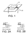
- a magnetic loss material 21 as a test sheet is disposed close to a transmission line 20 where electromagnetic noise conducts, i.e. unwanted high-frequency current flows.
- the transmission line 20 and the magnetic loss material 21 are inductively coupled.
- the transmission line 20 is given an equivalent resistance having frequency selectivity so that an equivalent circuit of the transmission line shown in Fig. 2A is changed to that shown in Fig. 2B.
- a resistance R given to the transmission line is approximately equal to zero in a signal frequency region (Signal) while the resistance R given to the transmission line is large in a noise frequency region (Noise).
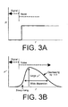
- the frequency dispersion of the imaginary part magnetic permeability ⁇ " must steeply rise. Since, the higher the frequency is, the loss characteristic P loss decreases slowly in response to reduction of the imaginary part magnetic permeability ⁇ ", if the frequency dispersion of the imaginary part magnetic permeability ⁇ " decreases gently after the steep rise, the loss can be maintained at a high level so that the excellent low-pass filter can be constituted. Moreover, in case of the profile which steeply rises and rapidly decreases thereafter, the excellent low-pass filter and the excellent band-eliminated filter can be obtained by designing a profile exhibiting the large dispersion over a wide frequency band.
- an ideal dispersion profile of the imaginary part magnetic permeability ⁇ " rises steeply in response to the rise of frequency and decreases gently thereafter.
- large dispersion over a wide frequency band provides excellent characteristics in case of the profile rising steeply and decreasing rapidly thereafter.
- the frequency characteristic of the magnetic loss material is given two different dispersion portions, i.e., first and second dispersion portions D1 and D2 having mutually different frequency regions to thereby achieve the dispersion profile of the imaginary part magnetic permeability that steeply rises and thereafter gently decreases.
- two magnetic powder groups different in frequency dispersion region are mixed.
- two magnetic powder groups different in frequency dispersion region from each other are prepared from one starting material by mechanical processing or the like.
- two frequency dispersion portions are achieved by a single kind of powder.
- magnetic materials in order to obtain a dispersion profile of the imaginary part magnetic permeability which rises steeply and exhibits a large dispersion over a wide frequency band, magnetic materials (magnetic powder) whose dispersions owing to the magnetic resonance are separated from each other by a desired frequency bandwidth are mixed together at an appropriate ratio.
- the dispersion of the imaginary part magnetic permeability that steeply rises and thereafter gently decreases can be obtained by the use of the powder having a single common composition.
- starting material powder is magnetic metal powder that is relatively brittle and when the powder is supplied to an agitated media mill such as a ball mill, relatively large powder is partly broken off to become fine powder.
- the fine powder is flattened under shearing stress of the media. As a result, the fine powder is further reduced in thickness.
- a thickness distribution of the powder is widened and may be separated into two thickness groups.
- one kind of starting material powder with the single common composition provides the imaginary part magnetic permeability having a dispersion profile comprising a first dispersion portion D1 at the high-frequency side owing to the eddy current and a second dispersion portion D2 at the low-frequency side owing to the magnetic resonance.
- the magnetic powder having a non-zero magnetostrictive constant may be Fe 3 O 4 (magnetite) or fine flat metal powder changed in composition under the shear stress by a ball mill and, as a result, given a non-zero magnetostrictive constant.
- Fe 3 O 4 magnetite
- fine flat metal powder changed in composition under the shear stress by a ball mill and, as a result, given a non-zero magnetostrictive constant.
- the surface area per powder unit weight is a predominant factor.
- the surface area that causes the two resonances is also dependent upon other factors that bring about the surface magnetic anisotropy, for example, the magnitude of a magnetoelastic effect, i.e. the magnitude of a magnetostrictive constant, and a magnitude of residual stress of.the powder, it is difficult to specify the value of the surface area in question.
- the soft magnetic powder having a specific surface area of 0.3m 2 /g or more.
- the above-mentioned powder provides no more than a dispersion profile showing a gentle dispersion at a low frequency side and a steep dispersion at a high-frequency side.
- the dispersion profile steeply rises at a low frequency side is obtained by a very narrow range of the specific surface area and heat treatment of the powder. The object of this invention can be achieved thereby.
- the imaginary part magnetic permeability ⁇ " has a first maximum values ⁇ " max (D1) that is the maximum within the first dispersion portion D1 and a second maximum value ⁇ " max (D2) that is the maximum within the second dispersion portion D2 and the second maximum value ⁇ " max (D2) is equal to or greater than the first maximum value ⁇ " max (D1).
- ⁇ fr" ⁇ D1 50 or ⁇ fr" ⁇ D2 50 is established where ⁇ fr" represents a difference between frequencies fr" max (D1) and fr" max (D2).
- fr" max (D1) represents the frequency where the imaginary part magnetic permeability ⁇ " has a first maximum value ⁇ " max (D1) and fr" max (D2) represents the frequency where the imaginary part magnetic permeability ⁇ " has a second maximum value ⁇ " max (D2)
- D1 50 represents a full width half maximum of the first dispersion portion D1
- D2 50 represents a full width half maximum of the second dispersion portion D2.
- a soft magnetic powder which includes first through (n+1)-th powders, where n is an integer not smaller than one.
- the first and the (n+1 )-th powders are different from each other in any one of the composition, the particle size, or the particle shape and are mixed together into the soft magnetic powder.
- n 1.
- two kinds of soft magnetic powder are used.
- the value of n may be 2 (embodiment using three kinds of soft magnetic powder), 3 (embodiment using four kinds of soft magnetic powder), and so on as far as a desired characteristic and a desired profile can be obtained.
- a soft magnetic paste was prepared with a composition shown in Table 1 and formed into a film by a doctor blade method. The film was then subjected to hot press and thereafter cured at 85°C for 24 hours.
- a magnetic loss material was obtained as a sample of the embodiment 1.
- component mixing ratio flat iron-aluminum-silicon alloy powder a 60wt. parts flat iron-aluminum-silicon alloy powder b 40wt. parts chlorinated polyethylene resin 10wt. parts solvent (toluene) 50wt. parts total 160wt. parts
- the dispersion resulting from the powder a is D2.
- the value of fr" maX (D2) is 26MHz and the full width half maximum D2 50 is 35MHz.
- the dispersion resulting from the powder b is D1.
- the value of fr" max (D1) is 161 MHz and the full width half maximum D1 50 is 320MHz.
- the relationship shows ⁇ fr" > D2 50 . It is argued here on the supposition that the relationship ⁇ fr" ⁇ D1 50 is also not satisfied, i.e., the relationship shows ⁇ fr" > D1 50 and ⁇ fr" > D2 50 . In this event, the ⁇ -f characteristic has a valley between D1 and D2 and the P loss characteristic indicates that the noise is allowed to pass. In this embodiment, the above-mentioned relationship ⁇ fr" ⁇ D1 50 is satisfied so that the valley will not be produced. Therefore, a desired attenuation characteristic is achieved.
- component mixing ratio teardrop-shaped nickel-iron alloy powder c 20wt. parts flat iron-aluminum-silicon alloy powder d 80wt. parts chlorinated polyethylene resin 10wt. parts solvent (toluene) 50wt. parts total 160wt. parts
- Iron-aluminum-silicon alloy ingot (10wt% Si 6wt% Al - the balance Fe) was prepared as starting material powder and subjected to stamp-mill grinding to thereby obtain coarse powder of an irregular shape having an average particle size of 40 ⁇ m.
- the iron-aluminum-silicon coarse powder having an irregular shape was supplied to a sand grinding mill together with n-hexane. The coarse powder was ground for 15 hours to obtain a powder sample e.
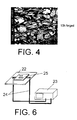
- a scanning electron microscope photograph of the powder sample e is shown in Fig. 4.
- the magnetic loss material was obtained as a sample of the third embodiment.
- component mixing ratio flat iron-aluminum-silicon alloy powder e 100wt. parts chlorinated polyethylene resin 10wt. parts solvent (toluene) 50wt. parts total 160wt. parts
- Fig. 5 shows a distribution of a thickness of the above-mentioned powder and the skin depth ⁇ s thereof after grinding for 15 hours.
- the skin depth ⁇ s is obtained by the following formula.
- ⁇ s ⁇ ⁇ f ⁇ [ ⁇ m]
- ⁇ represents an electric resistance [ ⁇ m], f, a frequency [Hz], ⁇ eff , magnetic permeability.
- the frequency f 100MHz
- ⁇ s 8.2 ⁇ m.
- the powder e has powder thickness distribution comprising two groups including the powder group similar in shape to the starting material coarse powder and the powder group of flat powder particles and the skin depth ⁇ s exists within the range of the powder thickness distribution.
- the third method will be described.
- Iron-aluminum-silicon alloy ingot (9.4wt% Si - 5.3wt% Al - the balance Fe) containing a greater ratio of iron as compared with the Sendust composition (9.6wt% Si - 5.4wt% Al - the balance Fe) and having a positive magnetostrictive constant was prepared as starting material powder.
- the starting material powder was subjected to stamp-mill grinding to thereby obtain coarse powder of an irregular shape having an average particle size of 40 ⁇ m.
- the resultant iron-aluminum-silicon alloy coarse powder of an irregular shape was put into a sand grinding mill together with n-hexane. The coarse powder was ground for 40 hours to obtain flat powder f having a B.E.T. specific surface area of 8.6m 2 /g.
- a soft magnetic paste was prepared with a composition shown in Table 4 and was formed into a film by a doctor blade method. The film was then subjected to hot pressing and thereafter cured at 85°C for 24 hours. Thus, a magnetic loss material was obtained as a sample of the embodiment 4.
- component mixing ratio flat iron-aluminum-silicon alloy powder f 100wt. parts chlorinated polyethylene resin 10wt. parts solvent (toluene) 50wt. parts total 160wt. parts
- a soft magnetic paste was prepared with a composition shown in Table 5 and formed into a film by a doctor blade method. The film was then subjected to hot pressing and thereafter cured at 85°C for 24 hours. Thus, a magnetic loss material was obtained as a sample of the embodiment 5.
- component mixing ratio flat iron-aluminum-silicon alloy powder g 100wt. parts chlorinated polyethylene resin 10wt. parts solvent (toluene) 50wt. parts total 160wt. parts
- Nickel-iron alloy ingot (77wt% Ni - 23wt% Fe) containing a greater ratio of iron than a Permalloy composition (80wt% Ni - 20wt% Fe) and having a positive magnetostrictive constant was prepared as starting material powder and subjected to stamp-mill grinding to thereby obtain coarse powder of an irregular shape having an average particle size of 25 ⁇ m.
- the nickel-iron alloy coarse powder of an irregular shape was put into a sand grinding mill together with n-hexane and ground for 8 hours to obtain fine flat powder h having a B.E.T. specific surface area of 0.39m 2 /g.
- a soft magnetic paste was prepared with a composition shown in Table 6 and formed into a film by a doctor blade method. The film was then subjected to hot pressing and thereafter cured at 85°C for 24 hours. Thus, a magnetic loss material was obtained as a sample of the embodiment 6.
- component mixing ratio flat nickel-iron alloy powder h 100wt. parts chlorinated polyethylene resin 10wt. parts solvent (toluene) 50wt. parts total 160wt. parts
- Fe 3 O 4 (Magnetite) powder i having a B.E.T. specific surface area of 1.97m 2 /g
- a soft magnetic paste was prepared with a composition shown in Table 7 and formed into a film by a doctor blade method. The film was then subjected to hot pressing. Thus, a magnetic loss material was obtained as a sample of the embodiment 7.
- component mixing ratio magnetite powder i 100wt. parts chlorinated polyethylene resin 10wt. parts solvent (toluene) 50wt. parts total 160wt. parts
- a soft magnetic paste was prepared with a composition shown in Table 8.
- a magnetic loss material was obtained as a sample of comparative example 1.
- component mixing ratio flat iron-aluminum-silicon alloy powder j 100wt. parts chlorinated polyethylene resin 10wt. parts solvent (toluene) 50wt. parts total 160wt. parts
- a soft magnetic paste was prepared with a composition shown in Table 9.
- a magnetic loss material was obtained as a sample of comparative example 2.
- component mixing ratio teardrop-shaped nickel-iron alloy powder c 100wt. parts chlorinated polyethylene resin 10wt. parts solvent (mixture of cyclohexanone and toluene) 50wt. parts total 160wt. parts
- ⁇ -f characteristic a frequency-dependent characteristic of a magnetic permeability ( ⁇ -f characteristic) and a conducted noise suppression effect were examined.
- ⁇ -f characteristic toroidal-shaped samples of the magnetic loss material were used.
- an imaginary part magnetic permeability ⁇ " was obtained over the frequency range from 1 MHz to 10GHz.
- a loss characteristic P loss was obtained using the following equation.
- P loss 1- [( ⁇ ) 2 + (T) 2 ]
- S 11 20log
- and S 21 20log
- . rand T represent a voltage reflection coefficient and a voltage transmission coefficient, respectively.
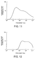
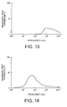
- each sample exhibited a dispersion profile of an imaginary part magnetic permeability that steeply rises and thereafter gently decreases due to manifestation of two imaginary part magnetic permeability dispersions in frequency regions different from each other or a frequency dispersion profile of an imaginary part magnetic permeability that steeply rises and maintains a large value of the imaginary part permeability ⁇ " over a wide frequency band.
- a frequency-dependent characteristic (1 MHz to 10GHz) of a conducted noise suppression effect P loss was actually examined.
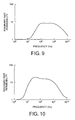
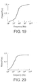
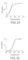
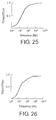
- Figs. 17 to 23 show frequency-dependent characteristics of P loss of the samples of the embodiments 1 to 7, while Figs. 24 to 26 show frequency-dependent characteristics of P loss of the samples of the comparative examples 1 to 3.
- each of the samples of the embodiments exhibits a frequency characteristic in which P loss representing the degree of conducted noise suppression steeply rises and is less attenuated thereafter, although a frequency region where P loss has large values is different among the samples.
- a magnetic material that can be used for producing the soft magnetic powder may be a soft magnetic metal material having a large value of the high-frequency permeability, such as silicon steel, an iron-aluminum-silicon alloy (Sendust), an iron-nickel alloy (Permalloy), or an amorphous alloy.
- the soft magnetic powder may be obtained from the above-mentioned soft magnetic material by grinding, drawing, tearing, atomization-granulation, or the like. As desired, the obtained powder may be further processed into a flat shape by the use of an agitated media mill such as a ball mill. Furthermore, the obtained powder and the flattened powder may be annealed.
- an oxide soft magnetic material such as spinel ferrite, planar ferrite, hematite, magnetite, or maghematite.
- thermoplastic resin such as polyester resin, polyethylene resin, polyvinyl chloride resin, polyvinyl butyral resin, polyurethane resin, cellulose resin, ABS resin, nitrile-butadiene rubber, styrene-butadiene rubber, or silicone rubber, copolymer thereof, and thermosetting resin such as epoxy resin, phenol resin, amide resin, or imide resin.
- the foregoing magnetic loss material has a frequency dispersion profile of the imaginary part magnetic permeability ⁇ " that steeply rises and thereafter gradually decreases or a frequency dispersion of the imaginary part magnetic permeability ⁇ " that steeply rises and maintains a large imaginary part magnetic permeability ⁇ " over a wide frequency band. Therefore, P loss as an index of a conducted noise suppression effect has a frequency characteristic which steeply rises and is less attenuated thereafter. Accordingly, by the use of the above-mentioned magnetic loss material, it is possible to effectively attenuate a noise component without adversely affecting a signal component. Therefore, the above-mentioned magnetic loss material has an excellent effect of suppressing the radiation of unwanted electromagnetic waves and is highly effective in preventing noise in an electronic component, particularly, a high-speed active element, a high-density printed wiring board, or the like.
Landscapes
- Engineering & Computer Science (AREA)
- Power Engineering (AREA)
- Physics & Mathematics (AREA)
- Electromagnetism (AREA)
- Chemical & Material Sciences (AREA)
- Dispersion Chemistry (AREA)
- Microelectronics & Electronic Packaging (AREA)
- Spectroscopy & Molecular Physics (AREA)
- Manufacturing & Machinery (AREA)
- Soft Magnetic Materials (AREA)
- Hard Magnetic Materials (AREA)
Applications Claiming Priority (2)
| Application Number | Priority Date | Filing Date | Title |
|---|---|---|---|
| JP2002252351 | 2002-08-30 | ||
| JP2002252351 | 2002-08-30 |
Publications (2)
| Publication Number | Publication Date |
|---|---|
| EP1394820A2 true EP1394820A2 (de) | 2004-03-03 |
| EP1394820A3 EP1394820A3 (de) | 2006-05-03 |
Family
ID=31492625
Family Applications (1)
| Application Number | Title | Priority Date | Filing Date |
|---|---|---|---|
| EP03019759A Withdrawn EP1394820A3 (de) | 2002-08-30 | 2003-08-29 | Weichmagnetischer Werkstoff und und Verfahren zur Herstellung |
Country Status (5)
| Country | Link |
|---|---|
| US (1) | US20040041121A1 (de) |
| EP (1) | EP1394820A3 (de) |
| KR (1) | KR20040020036A (de) |
| CN (1) | CN1492452A (de) |
| TW (1) | TW200409149A (de) |
Cited By (2)
| Publication number | Priority date | Publication date | Assignee | Title |
|---|---|---|---|---|
| GB2397441B (en) * | 2003-01-10 | 2006-11-01 | Murata Manufacturing Co | Noise filter |
| US20090123716A1 (en) * | 2005-03-22 | 2009-05-14 | Tohoku University | Magnetic Substance-Containing Insulator and Circuit Board and Electronic Device Using the Same |
Families Citing this family (32)
| Publication number | Priority date | Publication date | Assignee | Title |
|---|---|---|---|---|
| US7440593B1 (en) | 2003-06-26 | 2008-10-21 | Fotonation Vision Limited | Method of improving orientation and color balance of digital images using face detection information |
| US7616233B2 (en) | 2003-06-26 | 2009-11-10 | Fotonation Vision Limited | Perfecting of digital image capture parameters within acquisition devices using face detection |
| US7844076B2 (en) * | 2003-06-26 | 2010-11-30 | Fotonation Vision Limited | Digital image processing using face detection and skin tone information |
| US8682097B2 (en) * | 2006-02-14 | 2014-03-25 | DigitalOptics Corporation Europe Limited | Digital image enhancement with reference images |
| US9129381B2 (en) * | 2003-06-26 | 2015-09-08 | Fotonation Limited | Modification of post-viewing parameters for digital images using image region or feature information |
| US8593542B2 (en) * | 2005-12-27 | 2013-11-26 | DigitalOptics Corporation Europe Limited | Foreground/background separation using reference images |
| US7565030B2 (en) | 2003-06-26 | 2009-07-21 | Fotonation Vision Limited | Detecting orientation of digital images using face detection information |
| US8498452B2 (en) * | 2003-06-26 | 2013-07-30 | DigitalOptics Corporation Europe Limited | Digital image processing using face detection information |
| US7362368B2 (en) * | 2003-06-26 | 2008-04-22 | Fotonation Vision Limited | Perfecting the optics within a digital image acquisition device using face detection |
| US8948468B2 (en) * | 2003-06-26 | 2015-02-03 | Fotonation Limited | Modification of viewing parameters for digital images using face detection information |
| US7269292B2 (en) | 2003-06-26 | 2007-09-11 | Fotonation Vision Limited | Digital image adjustable compression and resolution using face detection information |
| US7792970B2 (en) | 2005-06-17 | 2010-09-07 | Fotonation Vision Limited | Method for establishing a paired connection between media devices |
| US8330831B2 (en) * | 2003-08-05 | 2012-12-11 | DigitalOptics Corporation Europe Limited | Method of gathering visual meta data using a reference image |
| US7680342B2 (en) | 2004-08-16 | 2010-03-16 | Fotonation Vision Limited | Indoor/outdoor classification in digital images |
| US9692964B2 (en) | 2003-06-26 | 2017-06-27 | Fotonation Limited | Modification of post-viewing parameters for digital images using image region or feature information |
| US7620218B2 (en) * | 2006-08-11 | 2009-11-17 | Fotonation Ireland Limited | Real-time face tracking with reference images |
| US8896725B2 (en) * | 2007-06-21 | 2014-11-25 | Fotonation Limited | Image capture device with contemporaneous reference image capture mechanism |
| US7574016B2 (en) | 2003-06-26 | 2009-08-11 | Fotonation Vision Limited | Digital image processing using face detection information |
| US7471846B2 (en) * | 2003-06-26 | 2008-12-30 | Fotonation Vision Limited | Perfecting the effect of flash within an image acquisition devices using face detection |
| US8155397B2 (en) * | 2007-09-26 | 2012-04-10 | DigitalOptics Corporation Europe Limited | Face tracking in a camera processor |
| US8989453B2 (en) * | 2003-06-26 | 2015-03-24 | Fotonation Limited | Digital image processing using face detection information |
| JP2005346806A (ja) * | 2004-06-02 | 2005-12-15 | Funai Electric Co Ltd | Dvdレコーダおよび記録再生装置 |
| US8320641B2 (en) | 2004-10-28 | 2012-11-27 | DigitalOptics Corporation Europe Limited | Method and apparatus for red-eye detection using preview or other reference images |
| US7315631B1 (en) | 2006-08-11 | 2008-01-01 | Fotonation Vision Limited | Real-time face tracking in a digital image acquisition device |
| US7965875B2 (en) | 2006-06-12 | 2011-06-21 | Tessera Technologies Ireland Limited | Advances in extending the AAM techniques from grayscale to color images |
| US7916897B2 (en) * | 2006-08-11 | 2011-03-29 | Tessera Technologies Ireland Limited | Face tracking for controlling imaging parameters |
| US7403643B2 (en) | 2006-08-11 | 2008-07-22 | Fotonation Vision Limited | Real-time face tracking in a digital image acquisition device |
| CN101536125B (zh) * | 2006-10-31 | 2011-12-14 | 索尼化学&信息部件株式会社 | 层合型软磁片的制备方法 |
| US8055067B2 (en) | 2007-01-18 | 2011-11-08 | DigitalOptics Corporation Europe Limited | Color segmentation |
| WO2010012448A2 (en) | 2008-07-30 | 2010-02-04 | Fotonation Ireland Limited | Automatic face and skin beautification using face detection |
| US8379917B2 (en) * | 2009-10-02 | 2013-02-19 | DigitalOptics Corporation Europe Limited | Face recognition performance using additional image features |
| JP7094622B2 (ja) * | 2018-03-29 | 2022-07-04 | 株式会社ディスコ | 環状の砥石 |
Family Cites Families (3)
| Publication number | Priority date | Publication date | Assignee | Title |
|---|---|---|---|---|
| JPH0993034A (ja) * | 1995-09-22 | 1997-04-04 | Tokin Corp | 複合磁性体及びその製造方法ならびに電磁干渉抑制体 |
| JP3404618B2 (ja) * | 1996-09-02 | 2003-05-12 | エヌイーシートーキン株式会社 | 電磁干渉抑制体 |
| JP2001210510A (ja) * | 2000-01-28 | 2001-08-03 | Tokin Corp | 軟磁性粉末及びそれを用いた複合磁性体 |
-
2003
- 2003-08-28 US US10/650,431 patent/US20040041121A1/en not_active Abandoned
- 2003-08-29 EP EP03019759A patent/EP1394820A3/de not_active Withdrawn
- 2003-08-29 KR KR1020030060165A patent/KR20040020036A/ko not_active Withdrawn
- 2003-08-29 TW TW092123861A patent/TW200409149A/zh unknown
- 2003-09-01 CN CNA031579698A patent/CN1492452A/zh active Pending
Cited By (2)
| Publication number | Priority date | Publication date | Assignee | Title |
|---|---|---|---|---|
| GB2397441B (en) * | 2003-01-10 | 2006-11-01 | Murata Manufacturing Co | Noise filter |
| US20090123716A1 (en) * | 2005-03-22 | 2009-05-14 | Tohoku University | Magnetic Substance-Containing Insulator and Circuit Board and Electronic Device Using the Same |
Also Published As
| Publication number | Publication date |
|---|---|
| TW200409149A (en) | 2004-06-01 |
| EP1394820A3 (de) | 2006-05-03 |
| CN1492452A (zh) | 2004-04-28 |
| KR20040020036A (ko) | 2004-03-06 |
| US20040041121A1 (en) | 2004-03-04 |
Similar Documents
| Publication | Publication Date | Title |
|---|---|---|
| EP1394820A2 (de) | Weichmagnetischer Werkstoff und und Verfahren zur Herstellung | |
| KR100247444B1 (ko) | 전자기 간섭 억제제용 복합 자석 | |
| Yoshida et al. | Crystal structure and microwave permeability of very thin Fe–Si–Al flakes produced by microforging | |
| JP4434422B2 (ja) | 高周波電流抑制型コネクタ | |
| JPH0935927A (ja) | 複合磁性体及びそれを用いた電磁干渉抑制体 | |
| JP3812977B2 (ja) | 電磁干渉抑制体 | |
| TW502261B (en) | Electronic component comprising a metallic case provided with a magnetic loss material | |
| US6495927B2 (en) | Resin-molded unit including an electronic circuit component | |
| KR20020034989A (ko) | 연자성 분말과 그것을 이용한 복합 자성재료 | |
| JP3404618B2 (ja) | 電磁干渉抑制体 | |
| JP3722391B2 (ja) | 複合磁性体およびそれを用いた電磁干渉抑制体 | |
| JP2002158486A (ja) | 電磁波吸収膜 | |
| EP1146637A1 (de) | Elektronisches Bauteil vom hochfrequenz Stromunterdrückungstyp und Bonddraht dafür | |
| JP4036300B2 (ja) | 磁気損失体及びその製造方法 | |
| JPH1083911A (ja) | 複合磁性体及びそれを用いた電磁干渉抑制体 | |
| JP2007173859A (ja) | 電磁干渉抑制体の製造方法 | |
| EP1166288B1 (de) | Magnetmaterial mit maximum-komplex-permeabilität in quasi-mikrowellenbereich und herstellungsverfahren | |
| JP4191888B2 (ja) | 電磁雑音抑制体およびそれを用いた電磁雑音の抑制方法 | |
| JP3979541B2 (ja) | 複合磁性体及びそれを用いた電磁干渉抑制体 | |
| JP3940188B2 (ja) | シート状の複合磁性体の製造方法 | |
| Ohnuma et al. | Noise suppression effect of soft magnetic Co-Pd-BO films with large è¬ Å and BS |
Legal Events
| Date | Code | Title | Description |
|---|---|---|---|
| PUAI | Public reference made under article 153(3) epc to a published international application that has entered the european phase |
Free format text: ORIGINAL CODE: 0009012 |
|
| AK | Designated contracting states |
Kind code of ref document: A2 Designated state(s): AT BE BG CH CY CZ DE DK EE ES FI FR GB GR HU IE IT LI LU MC NL PT RO SE SI SK TR |
|
| AX | Request for extension of the european patent |
Extension state: AL LT LV MK |
|
| PUAL | Search report despatched |
Free format text: ORIGINAL CODE: 0009013 |
|
| AK | Designated contracting states |
Kind code of ref document: A3 Designated state(s): AT BE BG CH CY CZ DE DK EE ES FI FR GB GR HU IE IT LI LU MC NL PT RO SE SI SK TR |
|
| AX | Request for extension of the european patent |
Extension state: AL LT LV MK |
|
| AKX | Designation fees paid | ||
| STAA | Information on the status of an ep patent application or granted ep patent |
Free format text: STATUS: THE APPLICATION IS DEEMED TO BE WITHDRAWN |
|
| 18D | Application deemed to be withdrawn |
Effective date: 20061104 |
|
| REG | Reference to a national code |
Ref country code: DE Ref legal event code: 8566 |