EP1394881A2 - Fluide de travail- système de refroidissement, en particulier pour un système de pile à combustible avec réformeur - Google Patents
Fluide de travail- système de refroidissement, en particulier pour un système de pile à combustible avec réformeur Download PDFInfo
- Publication number
- EP1394881A2 EP1394881A2 EP03016949A EP03016949A EP1394881A2 EP 1394881 A2 EP1394881 A2 EP 1394881A2 EP 03016949 A EP03016949 A EP 03016949A EP 03016949 A EP03016949 A EP 03016949A EP 1394881 A2 EP1394881 A2 EP 1394881A2
- Authority
- EP
- European Patent Office
- Prior art keywords
- operating medium
- cooling
- flow
- unit
- cooling system
- Prior art date
- Legal status (The legal status is an assumption and is not a legal conclusion. Google has not performed a legal analysis and makes no representation as to the accuracy of the status listed.)
- Withdrawn
Links
Images
Classifications
-
- H—ELECTRICITY
- H01—ELECTRIC ELEMENTS
- H01M—PROCESSES OR MEANS, e.g. BATTERIES, FOR THE DIRECT CONVERSION OF CHEMICAL ENERGY INTO ELECTRICAL ENERGY
- H01M8/00—Fuel cells; Manufacture thereof
- H01M8/06—Combination of fuel cells with means for production of reactants or for treatment of residues
- H01M8/0606—Combination of fuel cells with means for production of reactants or for treatment of residues with means for production of gaseous reactants
- H01M8/0612—Combination of fuel cells with means for production of reactants or for treatment of residues with means for production of gaseous reactants from carbon-containing material
- H01M8/0618—Reforming processes, e.g. autothermal, partial oxidation or steam reforming
-
- C—CHEMISTRY; METALLURGY
- C01—INORGANIC CHEMISTRY
- C01B—NON-METALLIC ELEMENTS; COMPOUNDS THEREOF; METALLOIDS OR COMPOUNDS THEREOF NOT COVERED BY SUBCLASS C01C
- C01B3/00—Hydrogen; Gaseous mixtures containing hydrogen; Separation of hydrogen from mixtures containing it; Purification of hydrogen; Reversible storage of hydrogen
- C01B3/02—Production of hydrogen; Production of gaseous mixtures containing hydrogen
- C01B3/32—Production of hydrogen; Production of gaseous mixtures containing hydrogen by reaction of gaseous or liquid organic compounds with gasifying agents, e.g. water, carbon dioxide or air
- C01B3/34—Production of hydrogen; Production of gaseous mixtures containing hydrogen by reaction of gaseous or liquid organic compounds with gasifying agents, e.g. water, carbon dioxide or air by reaction of hydrocarbons with gasifying agents
- C01B3/48—Production of hydrogen; Production of gaseous mixtures containing hydrogen by reaction of gaseous or liquid organic compounds with gasifying agents, e.g. water, carbon dioxide or air by reaction of hydrocarbons with gasifying agents followed by reaction of water vapour with carbon monoxide
-
- H—ELECTRICITY
- H01—ELECTRIC ELEMENTS
- H01M—PROCESSES OR MEANS, e.g. BATTERIES, FOR THE DIRECT CONVERSION OF CHEMICAL ENERGY INTO ELECTRICAL ENERGY
- H01M8/00—Fuel cells; Manufacture thereof
- H01M8/04—Auxiliary arrangements, e.g. for control of pressure or for circulation of fluids
- H01M8/04007—Auxiliary arrangements, e.g. for control of pressure or for circulation of fluids related to heat exchange
- H01M8/04029—Heat exchange using liquids
-
- H—ELECTRICITY
- H01—ELECTRIC ELEMENTS
- H01M—PROCESSES OR MEANS, e.g. BATTERIES, FOR THE DIRECT CONVERSION OF CHEMICAL ENERGY INTO ELECTRICAL ENERGY
- H01M8/00—Fuel cells; Manufacture thereof
- H01M8/06—Combination of fuel cells with means for production of reactants or for treatment of residues
- H01M8/0606—Combination of fuel cells with means for production of reactants or for treatment of residues with means for production of gaseous reactants
- H01M8/0612—Combination of fuel cells with means for production of reactants or for treatment of residues with means for production of gaseous reactants from carbon-containing material
- H01M8/0625—Combination of fuel cells with means for production of reactants or for treatment of residues with means for production of gaseous reactants from carbon-containing material in a modular combined reactor/fuel cell structure
- H01M8/0631—Reactor construction specially adapted for combination reactor/fuel cell
-
- C—CHEMISTRY; METALLURGY
- C01—INORGANIC CHEMISTRY
- C01B—NON-METALLIC ELEMENTS; COMPOUNDS THEREOF; METALLOIDS OR COMPOUNDS THEREOF NOT COVERED BY SUBCLASS C01C
- C01B2203/00—Integrated processes for the production of hydrogen or synthesis gas
- C01B2203/02—Processes for making hydrogen or synthesis gas
- C01B2203/0283—Processes for making hydrogen or synthesis gas containing a CO-shift step, i.e. a water gas shift step
- C01B2203/0288—Processes for making hydrogen or synthesis gas containing a CO-shift step, i.e. a water gas shift step containing two CO-shift steps
-
- C—CHEMISTRY; METALLURGY
- C01—INORGANIC CHEMISTRY
- C01B—NON-METALLIC ELEMENTS; COMPOUNDS THEREOF; METALLOIDS OR COMPOUNDS THEREOF NOT COVERED BY SUBCLASS C01C
- C01B2203/00—Integrated processes for the production of hydrogen or synthesis gas
- C01B2203/06—Integration with other chemical processes
- C01B2203/066—Integration with other chemical processes with fuel cells
-
- C—CHEMISTRY; METALLURGY
- C01—INORGANIC CHEMISTRY
- C01B—NON-METALLIC ELEMENTS; COMPOUNDS THEREOF; METALLOIDS OR COMPOUNDS THEREOF NOT COVERED BY SUBCLASS C01C
- C01B2203/00—Integrated processes for the production of hydrogen or synthesis gas
- C01B2203/08—Methods of heating or cooling
- C01B2203/0872—Methods of cooling
- C01B2203/0883—Methods of cooling by indirect heat exchange
-
- C—CHEMISTRY; METALLURGY
- C01—INORGANIC CHEMISTRY
- C01B—NON-METALLIC ELEMENTS; COMPOUNDS THEREOF; METALLOIDS OR COMPOUNDS THEREOF NOT COVERED BY SUBCLASS C01C
- C01B2203/00—Integrated processes for the production of hydrogen or synthesis gas
- C01B2203/16—Controlling the process
- C01B2203/1614—Controlling the temperature
- C01B2203/1619—Measuring the temperature
-
- H—ELECTRICITY
- H01—ELECTRIC ELEMENTS
- H01M—PROCESSES OR MEANS, e.g. BATTERIES, FOR THE DIRECT CONVERSION OF CHEMICAL ENERGY INTO ELECTRICAL ENERGY
- H01M2250/00—Fuel cells for particular applications; Specific features of fuel cell system
- H01M2250/20—Fuel cells in motive systems, e.g. vehicle, ship, plane
-
- H—ELECTRICITY
- H01—ELECTRIC ELEMENTS
- H01M—PROCESSES OR MEANS, e.g. BATTERIES, FOR THE DIRECT CONVERSION OF CHEMICAL ENERGY INTO ELECTRICAL ENERGY
- H01M8/00—Fuel cells; Manufacture thereof
- H01M8/06—Combination of fuel cells with means for production of reactants or for treatment of residues
- H01M8/0606—Combination of fuel cells with means for production of reactants or for treatment of residues with means for production of gaseous reactants
-
- Y—GENERAL TAGGING OF NEW TECHNOLOGICAL DEVELOPMENTS; GENERAL TAGGING OF CROSS-SECTIONAL TECHNOLOGIES SPANNING OVER SEVERAL SECTIONS OF THE IPC; TECHNICAL SUBJECTS COVERED BY FORMER USPC CROSS-REFERENCE ART COLLECTIONS [XRACs] AND DIGESTS
- Y02—TECHNOLOGIES OR APPLICATIONS FOR MITIGATION OR ADAPTATION AGAINST CLIMATE CHANGE
- Y02E—REDUCTION OF GREENHOUSE GAS [GHG] EMISSIONS, RELATED TO ENERGY GENERATION, TRANSMISSION OR DISTRIBUTION
- Y02E60/00—Enabling technologies; Technologies with a potential or indirect contribution to GHG emissions mitigation
- Y02E60/30—Hydrogen technology
- Y02E60/50—Fuel cells
-
- Y—GENERAL TAGGING OF NEW TECHNOLOGICAL DEVELOPMENTS; GENERAL TAGGING OF CROSS-SECTIONAL TECHNOLOGIES SPANNING OVER SEVERAL SECTIONS OF THE IPC; TECHNICAL SUBJECTS COVERED BY FORMER USPC CROSS-REFERENCE ART COLLECTIONS [XRACs] AND DIGESTS
- Y02—TECHNOLOGIES OR APPLICATIONS FOR MITIGATION OR ADAPTATION AGAINST CLIMATE CHANGE
- Y02T—CLIMATE CHANGE MITIGATION TECHNOLOGIES RELATED TO TRANSPORTATION
- Y02T90/00—Enabling technologies or technologies with a potential or indirect contribution to GHG emissions mitigation
- Y02T90/40—Application of hydrogen technology to transportation, e.g. using fuel cells
Definitions
- the invention relates to an operating medium cooling system, in particular one Fuel cell reformer system of a motor vehicle, according to the preamble of Claim 1.
- Cooling systems of the type mentioned are known. They serve, for example Fuel reforming or for reforming hydrocarbons (Operating medium) and are designed in particular as a heat exchanger system. through a heat exchanger system, it is possible in a relatively simple manner As part of an operating medium cooling, the heat given off within a To use the reforming process integratively.
- the operating medium e.g. a Reaction gas
- the operating medium is said to be practically constant by means of the cooling system Operating temperature to be cooled.
- Such an operating medium cooling is for example between a high temperature shift and a low temperature shift of a fuel cell reformer system by means of a cooling system.
- the known cooling systems have the disadvantage that the adjustable ones Temperatures of the operating medium are relatively high with the occurring Operating load changes, for example of a corresponding reformer system, vary and thus a precise operating medium temperature setting to a predeterminable Target temperature (target temperature) is not possible in the known cooling systems.
- target temperature a predeterminable Target temperature
- Such a load-dependent adaptation of the coolant mass flow depends on the heat capacity of each cooling medium and is Control engineering relatively complex.
- the operating medium cooling system is according to the invention characterized in that it contains an adjustable operating medium distributor element for Separation of an operating medium flow to be cooled into at least two Operating medium partial flows, the operating medium distribution element at least with a cooling unit which can be passed through by an associated operating medium partial flow Operating medium cooling system is connected.
- the Operating medium distributor element can be in a relatively simple manner Dependency of the occurring operating load changes of the cooling system Operating medium flow in two independent operating medium partial flows separate, the mass flow of a respective, an associated cooling unit penetrating operating medium partial flow by means of the operating medium distributor element is variable and thus also the cooling effect of a respective cooling unit by means of a Operating medium mass flow change is changeable.
- the operating medium partial flows can be associated cooling unit (for example, heat exchanger) with the same or different cooling media cooled to predefinable operating temperatures become. It is also conceivable to use only one of two operating medium partial flows to cool a cooling unit (heat exchanger), the respective mass flow of the cooling and the non-cooling operating medium partial flow by means of Operating medium distributor element is freely adjustable. If necessary, by means of Operating medium distribution element also the total mass flow of the Operating medium flow can be varied, for example using one with the Operating medium distributor element connected operating medium buffer.
- An operating medium partial stream mixing unit is advantageously arranged downstream of the cooling unit for mixing the operating medium partial streams to form a cooled operating medium stream.
- the operating medium partial flow mixing unit thus serves to bring together the operating medium partial flows generated by means of the operating medium distribution element to form a cooled operating medium flow.
- the operating medium partial flow mixing unit can also preferably be set automatically and can be used for additional mass flow setting, in particular when using a respective operating medium partial flow buffer. Since the different operating medium partial flow mass flows have different temperatures, the operating temperatures of the operating medium flow on the outlet side of the operating medium partial flow mixing unit can also be set in a relatively simple manner by setting the respective mass flows in the operating medium partial flow mixing unit.
- the operating medium distributor element is preferably connected on its outlet side, with the formation of a parallel arrangement, to the cooling unit and to the operating medium partial flow mixing unit.
- only one operating medium partial stream is cooled to a predeterminable temperature by means of the cooling unit, while the second operating medium partial stream is not cooled, but is instead passed directly to the operating medium partial stream mixing unit, by means of which it is combined with the cooled operating medium partial stream, preferably forming one constant and predeterminable temperature of cooled operating medium flow.
- the operating medium distributor element is advantageously also on its entry side a precooling unit that can be penetrated by the operating medium flow.
- the Pre-cooling unit is the total mass flow of the operating medium to one preferably predeterminable temperature, so that a to the Operating load change of the cooling system (or the reformer system) adapted cooling of the operating medium or at least one Operating medium partial flow takes place by means of the cooling unit interspersed with the same.
- the Use of two independent cooling units allows particularly flexible, adaptable cooling of the operating medium to a predefinable and constant operating temperature.
- the Cooling media of the pre-cooling unit and the cooling unit of the operating medium cooling device be different from each other (for example in the form of a cooling gas, one Coolant or a suitable mixture).
- the cooling system is as Formed heat exchanger device and are the cooling unit and possibly the Pre-cooling unit one heat exchanger each. Trained as a heat exchanger Cooling units are particularly suitable for effective and control technology relatively easy to use or control Operating medium cooling in the cooling system.
- the heat exchanger can be used as Co-current heat exchanger, counter-current heat exchanger and / or as Cross-flow heat exchanger can be formed.
- the pre-cooling unit with one cooling air flow and the cooling unit with one are advantageous Coolant flow, in particular a cooling water flow, enforceable.
- the Selection of cooling media for the cooling unit and for the pre-cooling unit depends in particular on the target operating temperature of the operating medium to be set. Alternatively, gas and / or liquid mixtures can also be used as cooling media Come into play.
- the cooling line system of the cooling unit and / or the pre-cooling unit is preferably with at least one further functional unit, in particular the Fuel cell system connected.
- the use of a the cooling unit and / or the respective cooling medium heated in the pre-cooling unit Preheating of a feed stream, for example in the fuel cell system. It can therefore be an integrated and more economical in the fuel cell system Heat flow can be realized.
- the cooling unit is on it Outlet side connected to the operating medium partial flow mixing unit in particular with the interposition of a condensate separator.
- the condensate separator serves for condensing, for example, liquid water from the cooled Operating medium partial flow especially when starting the still cold cooling system.
- the operating medium can, for example, be a reformate gas produced by a High temperature shift to a low temperature shift with the interposition of the Operating medium-cooling system. is feasible.
- the cooling system can additionally or alternatively also to solve other, corresponding cooling tasks, for example can be used within the fuel cell system while achieving the aforementioned advantages.
- a control system is advantageously provided for controlling the Operating medium distribution element depending on a target-actual temperature difference of cooled operating medium flow.
- Such a control system allows a quick one and reliable division of operating medium into several operating medium partial flows Achieving flexible operating medium cooling.
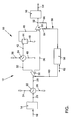
- the single figure shows a flow diagram to illustrate an inventive Operating medium cooling system that is part of a fuel cell reformer system.
- the figure shows a generally designated 10 using a flow diagram Fuel cell reformer system that includes a high temperature shift 14 and one Low temperature shift 16 with the interposition of an inventive Operating medium cooling system 12.
- the high temperature shift 14 is according to Arrow 18 is charged with an operating medium and is at its outlet with a Heat exchanger 22 (pre-cooling unit) connected to the same in accordance with Arrow 20 with an operating medium flow.
- the operating medium flow (arrow 20) is in the pre-cooling unit 22 by means of a cooling medium (cooling air flow) according to arrow 24 pre-cooled.
- the cooling air flow thus heated is preferred according to arrow 26 a further functional unit (not shown in the figure) of the Fuel cell system fed to an additional heat use of the To allow cooling air flow (arrow 26) within the fuel cell system.
- the Pre-cooled operating medium flow is then a Operating medium distributor element 30 fed to the division of the Operating medium flow (arrow 28) in two separate Operating medium partial flows according to arrows 32, 36 is used.
- the Operating medium partial flows 32, 36 have different sized mass flows. one the operating medium partial flows is without further cooling treatment according to arrow 36 from the operating medium distribution element 30 to an operating medium partial flow mixing unit 50 led, while the second operating medium partial flow 32 to another Heat exchanger 34 (cooling unit) is passed.
- the cooling unit 34 is used with respect to FIG Operating load change of the fuel cell reformer system 10 adapted cooling of the same penetrating operating medium partial flow 32, one for cooling Cooling medium 38 in the form of a cooling liquid flow, in particular one Cooling water flow is used.
- the one heated in the cooling unit 34 Coolant flow (arrow 40) is also not used for further heat use the functional unit of the fuel cell system shown in the figure.
- the on a predeterminable operating temperature cooled operating medium partial flow is from the Cooling unit 34 according to arrow 42 fed to a condensate separator 44 by means of which condensate, if any, according to arrow 46 from the Operating medium partial flow (arrow 42) is discharged.
- the remaining one Operating medium partial flow is downstream of the condensate separator 44 according to Arrow 48 of the operating medium partial flow mixing unit 50, by means of which a Mixing of the two downstream of the operating medium distributor element 30 Operating medium partial flows formed (arrows 48, 36) take place with the formation of a a target operating temperature of cooled operating medium flow (arrow 52).
- the chilled one Operating medium stream 52 is fed to the low-temperature shift 16, of which an operating medium according to arrow 54 to a further functional unit of the Fuel cell system can be directed.
- This data are evaluated for controlling the operating medium distributor element 30 in Dependency of a target-actual temperature difference of the cooled operating medium flow (Arrow 52).
- the control system 56 by means of a control line (arrow 60) operatively connected to the adjustable operating medium distributor element 30.
- the Control system 56 can, according to double arrow 62, optionally also with others Functional units of the fuel cell system or the motor vehicle in connection stand.
- the fuel cell reformer system 10 permits efficient reforming of Hydrocarbons for fuel cell applications, as in the heat exchangers 22, 34 released heat by means of a corresponding cooling medium flow (arrows 26, 40) for example for further educt preheating within the Fuel cell system can be used.
- a meaningful use of Operating medium waste heat is particularly at relatively high temperatures, For example, greater than 400 ° C, effective and therefore advantageous.
- are part of a Reforming process for the individual process stages relatively narrow Observe the operating temperature ranges of the operating medium so that accordingly, a precise and effective use of waste heat in the Fuel cell system can be planned.
- the heat exchangers 22, 34 can be, for example, cocurrent, countercurrent and / or Cross-flow heat exchanger can be formed. It can in Heat exchanger 22 (pre-cooling unit) with air saturated with moisture as a cooling medium for Come into play.
- the available mass flow of air (arrow 24) as the cooling medium is however not sufficient to achieve a predefinable and constant target temperature (target temperature) of the operating medium flow (arrow 28).
- target temperature target temperature
- the relatively small cooling medium mass flow (arrow 24) becomes a relatively high one Temperature of the coolant flow (arrow 26) at the outlet of the heat exchanger 22 achieved. This can help improve the efficiency of the fuel cell reformer system 10 can be used by the heated coolant flow (arrow 26) is used as a starting material for reforming.
- the heat exchanger 34 is dimensioned such that the operating medium flow (Arrow 28) even when the operating load changes in the fuel cell reformer system 10 almost cooled to the temperature of the cooling medium (arrow 38) becomes.
- the control system 56 allows control the distribution of the operating medium flow (arrow 28) using the Operating medium distributor element 30 in two operating medium partial flows (arrows 32, 36) in Dependence of the actual temperature or the target actual temperature difference of the cooled operating medium flow (arrow 52).
- operating medium distributor element 30 For example, throttle valves or proportional valves can be used.
- the operating medium cooling system 12 By means of the operating medium cooling system 12, one that may occur Operating load change of the fuel cell reformer system 10 adapted cooling the Operating medium flow (arrow 20) to a constant temperature (arrow 52) possible.
- the temperature setting can be relatively simple in terms of control technology by means of temperature-controlled adjustment of a throttle valve and / or one Proportional valve (operating medium distributor element 30) take place.
- the overall efficiency of the fuel cell reformer system 10 or the fuel cell system through additional use of Waste heat obtained for preheating the educt to improve with the formation of a heat circuit as closed as possible.
Landscapes
- Chemical & Material Sciences (AREA)
- Chemical Kinetics & Catalysis (AREA)
- Engineering & Computer Science (AREA)
- General Chemical & Material Sciences (AREA)
- Sustainable Energy (AREA)
- Sustainable Development (AREA)
- Manufacturing & Machinery (AREA)
- Electrochemistry (AREA)
- Life Sciences & Earth Sciences (AREA)
- Organic Chemistry (AREA)
- Health & Medical Sciences (AREA)
- General Health & Medical Sciences (AREA)
- Combustion & Propulsion (AREA)
- Inorganic Chemistry (AREA)
- Fuel Cell (AREA)
- Hydrogen, Water And Hydrids (AREA)
Applications Claiming Priority (2)
| Application Number | Priority Date | Filing Date | Title |
|---|---|---|---|
| DE10237450 | 2002-08-16 | ||
| DE10237450A DE10237450A1 (de) | 2002-08-16 | 2002-08-16 | Betriebsmedium-Kühlsystem, insbesondere eines Brennstoffzellen-Reformersystems |
Publications (2)
| Publication Number | Publication Date |
|---|---|
| EP1394881A2 true EP1394881A2 (fr) | 2004-03-03 |
| EP1394881A3 EP1394881A3 (fr) | 2006-10-04 |
Family
ID=30775309
Family Applications (1)
| Application Number | Title | Priority Date | Filing Date |
|---|---|---|---|
| EP03016949A Withdrawn EP1394881A3 (fr) | 2002-08-16 | 2003-07-25 | Fluide de travail- système de refroidissement, en particulier pour un système de pile à combustible avec réformeur |
Country Status (2)
| Country | Link |
|---|---|
| EP (1) | EP1394881A3 (fr) |
| DE (1) | DE10237450A1 (fr) |
Citations (1)
| Publication number | Priority date | Publication date | Assignee | Title |
|---|---|---|---|---|
| US3441393A (en) | 1966-01-19 | 1969-04-29 | Pullman Inc | Process for the production of hydrogen-rich gas |
Family Cites Families (5)
| Publication number | Priority date | Publication date | Assignee | Title |
|---|---|---|---|---|
| EP0200825A1 (fr) * | 1985-05-08 | 1986-11-12 | Exxon Research And Engineering Company | Procédé de réformage d'hydrocarbure à la vapeur utilisant des surchauffeurs de vapeur disposés en séries |
| DE4432292B4 (de) * | 1993-03-13 | 2006-05-11 | Phoenix Ag | Verteilereinrichtung für das Kühl- bzw. Heizsystem von Fahrzeugen mit Verbrennungsmotoren |
| DE4327261C1 (de) * | 1993-08-13 | 1994-10-13 | Daimler Benz Ag | Kühlmittelkreislauf |
| GB9714744D0 (en) * | 1997-07-15 | 1997-09-17 | Ici Plc | Methanol |
| DE19961825A1 (de) * | 1999-12-21 | 2001-06-28 | Valeo Klimasysteme Gmbh | Kühl-Heiz-Kreis mit zwei Kühlern |
-
2002
- 2002-08-16 DE DE10237450A patent/DE10237450A1/de not_active Withdrawn
-
2003
- 2003-07-25 EP EP03016949A patent/EP1394881A3/fr not_active Withdrawn
Patent Citations (1)
| Publication number | Priority date | Publication date | Assignee | Title |
|---|---|---|---|---|
| US3441393A (en) | 1966-01-19 | 1969-04-29 | Pullman Inc | Process for the production of hydrogen-rich gas |
Also Published As
| Publication number | Publication date |
|---|---|
| DE10237450A1 (de) | 2004-02-26 |
| EP1394881A3 (fr) | 2006-10-04 |
Similar Documents
| Publication | Publication Date | Title |
|---|---|---|
| DE102014111971B4 (de) | Klimaanlage für ein Fahrzeug | |
| EP1533116B1 (fr) | Dispositif pour contrôler la température d'une machine à imprimer | |
| EP0945291A1 (fr) | Dispositif et procédé pour chauffer et réfrigérer l'espace de chargement d'un véhicule | |
| EP2423482B1 (fr) | Système de refroidissement pour un véhicule | |
| EP2287952A1 (fr) | Dispositif de régulation | |
| DE102019104747A1 (de) | Wärmeenergierückgewinnungsstrategie aus Kraftfahrzeugabgasen | |
| AT513052B1 (de) | Verbrennungsmotor-Reformer-Anlage | |
| DE102018124755A1 (de) | Dual-Expansionsventil | |
| EP3690353B1 (fr) | Procédé de fonctionnement d'un agencement de régulation thermique, agencement de régulation thermique et véhicule | |
| DE10245257A1 (de) | Wärmemanagementvorrichtung für ein Kraftfahrzeug | |
| EP1394881A2 (fr) | Fluide de travail- système de refroidissement, en particulier pour un système de pile à combustible avec réformeur | |
| EP3075582B1 (fr) | Systeme de thermoregulation de vehicule automobile et son procede de fonctionnement | |
| DE102014219952A1 (de) | Aufgeladene Brennkraftmaschine sowie Fahrzeug | |
| EP1743688B1 (fr) | Procédé et dispositif pour la cryocondensation | |
| DE102009039326A1 (de) | Wärmepumpe | |
| EP3515733B1 (fr) | Dispositif de climatisation pour véhicule automobile et procédé permettant de faire fonctionner ledit dispositif | |
| AT524819B1 (de) | Wärmekopplungsvorrichtung für ein Brennstoffzellensystem | |
| DE102019119124A1 (de) | Kombinationswärmetauscher mit einem Chiller und einem inneren Wärmetauscher sowie Kühl-Kälte-Kreislaufsystem und Kraftfahrzeug mit einem solchen | |
| DE102017004583B4 (de) | Kühlsystem für einen Verbrennungsmotor und ein weiteres Objekt | |
| EP1674140B1 (fr) | Procédé et appareil pour condensation partielle | |
| EP3490825B1 (fr) | Dispositif de climatisation pour véhicule automobile et procédé permettant de faire fonctionner ledit dispositif | |
| DE102004046459B3 (de) | Klimaanlage für ein Fahrzeug, insbesondere für ein Kraftfahrzeug | |
| DE102005005430A1 (de) | Verfahren zum Betreiben einer Klimaanlage | |
| DE3941713A1 (de) | Vorrichtung zum kuehltrocknen von gasen | |
| DE102016219205A1 (de) | Mehrpassiger Luft/Kältemittel-Wärmeübertrager, Klimatisierungsvorrichtung für ein Kraftfahrzeug und Kraftfahrzeug |
Legal Events
| Date | Code | Title | Description |
|---|---|---|---|
| PUAI | Public reference made under article 153(3) epc to a published international application that has entered the european phase |
Free format text: ORIGINAL CODE: 0009012 |
|
| AK | Designated contracting states |
Kind code of ref document: A2 Designated state(s): AT BE BG CH CY CZ DE DK EE ES FI FR GB GR HU IE IT LI LU MC NL PT RO SE SI SK TR |
|
| AX | Request for extension of the european patent |
Extension state: AL LT LV MK |
|
| PUAL | Search report despatched |
Free format text: ORIGINAL CODE: 0009013 |
|
| AK | Designated contracting states |
Kind code of ref document: A3 Designated state(s): AT BE BG CH CY CZ DE DK EE ES FI FR GB GR HU IE IT LI LU MC NL PT RO SE SI SK TR |
|
| AX | Request for extension of the european patent |
Extension state: AL LT LV MK |
|
| 17P | Request for examination filed |
Effective date: 20070404 |
|
| AKX | Designation fees paid |
Designated state(s): AT BE BG CH CY CZ DE DK EE ES FI FR GB GR HU IE IT LI LU MC NL PT RO SE SI SK TR |
|
| 17Q | First examination report despatched |
Effective date: 20071122 |
|
| STAA | Information on the status of an ep patent application or granted ep patent |
Free format text: STATUS: THE APPLICATION IS DEEMED TO BE WITHDRAWN |
|
| 18D | Application deemed to be withdrawn |
Effective date: 20091222 |