EP1395013A1 - Verfahren und Vorrichtung zur Datenübertragung über eine Versorgungsleitungsträgerwelle - Google Patents
Verfahren und Vorrichtung zur Datenübertragung über eine Versorgungsleitungsträgerwelle Download PDFInfo
- Publication number
- EP1395013A1 EP1395013A1 EP03015653A EP03015653A EP1395013A1 EP 1395013 A1 EP1395013 A1 EP 1395013A1 EP 03015653 A EP03015653 A EP 03015653A EP 03015653 A EP03015653 A EP 03015653A EP 1395013 A1 EP1395013 A1 EP 1395013A1
- Authority
- EP
- European Patent Office
- Prior art keywords
- signal
- transmission
- axis
- transmission data
- data
- Prior art date
- Legal status (The legal status is an assumption and is not a legal conclusion. Google has not performed a legal analysis and makes no representation as to the accuracy of the status listed.)
- Withdrawn
Links
Images










Classifications
-
- H—ELECTRICITY
- H04—ELECTRIC COMMUNICATION TECHNIQUE
- H04L—TRANSMISSION OF DIGITAL INFORMATION, e.g. TELEGRAPHIC COMMUNICATION
- H04L27/00—Modulated-carrier systems
- H04L27/26—Systems using multi-frequency codes
- H04L27/2601—Multicarrier modulation systems
- H04L27/2602—Signal structure
- H04L27/2605—Symbol extensions, e.g. Zero Tail, Unique Word [UW]
-
- H—ELECTRICITY
- H04—ELECTRIC COMMUNICATION TECHNIQUE
- H04L—TRANSMISSION OF DIGITAL INFORMATION, e.g. TELEGRAPHIC COMMUNICATION
- H04L25/00—Baseband systems
- H04L25/02—Details ; arrangements for supplying electrical power along data transmission lines
- H04L25/03—Shaping networks in transmitter or receiver, e.g. adaptive shaping networks
- H04L25/03006—Arrangements for removing intersymbol interference
- H04L25/03343—Arrangements at the transmitter end
-
- H—ELECTRICITY
- H04—ELECTRIC COMMUNICATION TECHNIQUE
- H04L—TRANSMISSION OF DIGITAL INFORMATION, e.g. TELEGRAPHIC COMMUNICATION
- H04L27/00—Modulated-carrier systems
- H04L27/26—Systems using multi-frequency codes
- H04L27/2601—Multicarrier modulation systems
- H04L27/2626—Arrangements specific to the transmitter only
- H04L27/26265—Arrangements for sidelobes suppression specially adapted to multicarrier systems, e.g. spectral precoding
-
- H—ELECTRICITY
- H04—ELECTRIC COMMUNICATION TECHNIQUE
- H04L—TRANSMISSION OF DIGITAL INFORMATION, e.g. TELEGRAPHIC COMMUNICATION
- H04L27/00—Modulated-carrier systems
- H04L27/26—Systems using multi-frequency codes
- H04L27/2601—Multicarrier modulation systems
- H04L27/2626—Arrangements specific to the transmitter only
- H04L27/2627—Modulators
- H04L27/2644—Modulators with oversampling
-
- H—ELECTRICITY
- H04—ELECTRIC COMMUNICATION TECHNIQUE
- H04L—TRANSMISSION OF DIGITAL INFORMATION, e.g. TELEGRAPHIC COMMUNICATION
- H04L25/00—Baseband systems
- H04L25/02—Details ; arrangements for supplying electrical power along data transmission lines
- H04L25/03—Shaping networks in transmitter or receiver, e.g. adaptive shaping networks
- H04L25/03006—Arrangements for removing intersymbol interference
- H04L2025/0335—Arrangements for removing intersymbol interference characterised by the type of transmission
- H04L2025/03375—Passband transmission
- H04L2025/03414—Multicarrier
Definitions
- the present invention relates to a data transmission method and a data transmission device. Specifically, the present invention relates to a data transmission method and a data transmission device that can be applied to a power line carrier communication modem and the like for high speed data communication using a power line, wherein a leak electromagnetic field (electromagnetic wave) that is radiated from the power line at the time of signal transmission can be suppressed. That is, the present invention relates to a data transmission method and a data transmission device that have a function of suppressing a leak electromagnetic field to reduce a noise applied to other receivers, while signal transmission is performed therethrough.
- a leak electromagnetic field electromagnetic wave
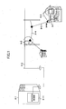
- Fig. 1 shows an example of a configuration of a power line carrier communication system.
- a power line includes a high-voltage distribution power line 9-2 of 6.6 kV provided between a power distribution transformer substation 9-1 and a pole transformer 9-3, and a 100V/200V low-voltage power distribution line 9-4 and a service line 9-5 provided between the pole transformer 9-3 and a house 9-6.
- an optical fiber is provided between an access node 9-11 of the power distribution transformer substation 9-1 and a modem inside the pole transformer 9-3 so as to enable data transmission with an optical signal. Further, data transmission can be performed between the pole transformer 9-3 and a modem of the house 9-6 whose plug is inserted into an outlet of the house 9-6, via the low-voltage power distribution line 9-4, the service line 9-5, and wiring 9-7 in the house 9-6.
- Plural home electric appliances are connected to the low-voltage power distribution line 9-4, the service line 9-5, and the wiring 9-7, so that switching power sources and inverter circuits of these home electric appliances randomly generate noises to deteriorate communication quality in the above data transmission. For this reason, the following techniques are applied. That is, an FM modulation method, an FSK modulation method, a PSK modulation method, a spectrum diffusion method, and the like that are robust against noises are used. Alternatively, a multi-carrier modulation method, OFDM (Orthogonal Frequency Division Multiplexing), and the like are introduced to perform communication while avoiding use of carrier bands having many noises.
- OFDM Orthogonal Frequency Division Multiplexing
- a radiated leak electromagnetic field generated from the power line at the time of the signal transmission can adversely affect broadcasting media or other communications.
- the noises can adversely affect a receiver for short-wave broadcasting to deteriorate quality in a voice of the broadcasting.
- the transmission level in the power line carrier communication may be lowered.
- communication quality in the power line carrier communication is substantially lowered by noises generated from the switching sources and the inverters of the various home electric appliances.
- Fig. 2 shows an equivalent circuit of the power line in which the reflected waves are generated by the multi-paths.
- the reference number 10-1 designates a transmission unit of the modem of the pole transformer
- the reference number 10-2 designates a reception unit of the modem of the house.
- the pole transformer modem transmission unit 10-1 is connected to the house modem reception unit 10-2 by the power line 10-3 having many branching points.
- the "n" number of reflected waves that are generated by the reflection at many branching points spend respective delay times ⁇ t1 through ⁇ tn, and then are returned to the power line at the side of the pole transformer modem transmission unit 10-1 to be combined.
- the reflected wave and the carrier wave of the transmission signal overlap to generate a point where a voltage value becomes zero, that is, a point where the impedance becomes zero. Accordingly, at this point, a large current signal flows to generate a large leak electromagnetic field.
- a low-voltage power distribution line can function as an inductor for the pole transformer modem, and a service line and wiring in a house can function as a condenser for the pole transformer modem.
- a noise preventing condenser of each home electronic appliance connected to the wiring in the house is provided between AC 100V lines, so that each home electric appliance generates a large capacitance load.
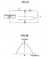
- the power line can function as a series resonance circuit including an output impedance, i.e., including R, L, and C.
- Fig. 3A shows this equivalent circuit of the power line from the viewpoint of the pole transformer modem.
- Fig. 3B shows frequency characteristics of a signal current flowing in the power line.
- R designates the output impedance of the pole transformer modem
- L designates an inductor of the low-voltage power distribution line
- C designates a condenser produced by the service line and the wiring in the house.
- R, C, and L constitute the series resonance circuit.
- the signal having this resonance frequency causes a large current to flow, so that a large leak electromagnetic field wave is generated.
- Figs. 4A and 4B show a plurality of resonance points in the range of the frequency band of the transmission signal.
- Figs. 4A and 4B show the change in the impedance and the flowing current that depend on a frequency value.
- the impedance takes minimum values at several points indicated by the arrows in Figs. 4A and 4B. Accordingly, at the minimum values of the impedance, the current takes maximum values to generate a large leak electromagnetic wave.
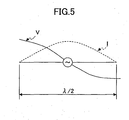
- each branching circuit functions as an antenna.
- the resonance frequency is 30 MHz
- the transmission speed of the radio wave becomes 3 ⁇ 10 8 [m/s]
- the wave length of the radio wave becomes 10 m.
- a node is generated at intervals of the half wave length that is 5 m.
- the maximum current or the maximum voltage is generated.
- frequencies having values that are integral multiples of the resonance frequency also cause the resonance. Accordingly, large leak electromagnetic fields are generated at intervals of half wave lengths of these resonance frequencies. Since the electric home appliance has capacity load, a large electromagnetic field is ' generated at intervals of the half wave length of the resonance frequency larger than about 100 kHz.
- a communication line such as a power line, a telephone line, and a coaxial transmission line that generates a reflected wave
- a large current caused by the reflected wave and caused by intersymbol interference can be prevented from flowing to suppress the leak electromagnetic field.
- a method of transmitting data comprising the steps of:
- the step (a) comprises the step (c) of performing the predetermined processing on the transmission data on the frequency axis such that the inverted signal and at least one zero signal point are inserted between the transmission signals on the time axis.
- the step (a) comprises the step (d) of copying the transmission data on the frequency axis
- the step (b) comprises the step (e) of processing the transmission data and the copied transmission data in parallel.
- the step (a) comprises the step (f) of performing the predetermined processing on the transmission data such that the transmission signal of the transmission data is delayed by a predetermined time, and the delayed transmission signal is subtracted from the transmission signal.
- the method further comprises the step (g) of decreasing a roll-off rate of frequency characteristics in the processing of the step (f).
- the step (b) comprises the step (h) of transforming the transmission data processed in the step (a) into the time-axis signal by using inverse fast Fourier transform processing.
- the step (d) comprises the step (i) of determining a first number of points that are assigned to the transmission data such that data of both the transmission data and the copied transmission data corresponds to a second number of points that is a number of carriers used in the inverse fast Fourier transform processing.
- the step (d) comprises the step (j) of adjusting the number of times of copying the transmission data, the number of times of copying being the number of times of generating transmission data by copying the transmission data.
- a data transmission device comprising:
- the frequency-axis processing means perform the predetermined processing on the transmission data on the frequency- axis such that the inverted signal and at least one zero signal point are inserted between the transmission signals of the transmission data on the time axis.
- the frequency-axis processing means comprise copying means for copying the transmission data on the frequency axis, and the time-axis transform means process the transmission data and the copied transmission data in parallel.
- the frequency-axis processing means comprise delay finite-difference means for delaying the transmission signal, and subtracting the delayed transmission signal from the transmission signal.
- the delay finite-difference means use a decreased roll-off rate of frequency characteristics in the frequency-axis processing means.
- the time-axis transform means transform the transmission data processed by the frequency-axis processing means into the time-axis signal by using inverse fast Fourier transform processing.
- the copying means determine a first number of points that are assigned to the transmission data such that data of both the transmission data and the copied transmission data corresponds to a second number of points that is a number of carriers used in the inverse fast Fourier transform processing.
- the copying means adjust the number of copies of the transmission data generated by the copying means.
- the zero point inserting process or the inverted signal point inserting process can be performed before the data on the frequency axis can be transformed into the data on the time axis by an inverse fast Fourier transform process and the like. Furthermore, the number of signal points to which the transmission data is assigned can be determined such that the data obtained after the zero point inserting process or the inverted signal point inserting process agrees with the number (the carrier number) of the points that are used when the data on the frequency axis is transformed into the data on the time axis. Accordingly, the configuration for transforming the data on the frequency axis into the data on the time axis can be made so as to process the fixed number of the points, resulting in the simplified configuration.
- a power line becomes an equivalent circuit as shown in Fig. 6A due to a branching circuit.
- Consecutively transmitted signals and the reflected and returned signals that are generated by the reflection of the transmitted signals are combined while the reflected signals have the opposite phases of those of the transmission signals.
- maximum currents are generated at several points.
- the width (period) of the thus-generated impulse response wave in the power line becomes about 2 ⁇ s at most, for example.
- the impulse corresponding to the transmission data is transmitted at the intervals of 2 ⁇ s, as shown in Fig. 6C.
- Nyquist transmission of the impulse is performed by the high band region (e.g., 30 M baud) that is allowed in the power line.
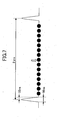
- Zero points indicated by the filled circles of Fig. 7 are provided at the Nyquist intervals (e.g., about 33 ns) between the impulses, as shown in Fig. 7.
- the impulses are transmitted at the intervals that are the impulse response periods (about 2 ⁇ s) of the power line, in order to prevent respective impulse responses from overlapping. In this manner, it is possible to suppress the reflected wave interference and the intersymbol interference, and to prevent a large current from flowing, reducing a leak electromagnetic field.
- a first impulse is transmitted, and a second impulse having a phase (inverted phase) that is shifted from the phase of the first impulse by 180 degrees is then transmitted so as to reduce the reflected waves and suppress a leak electromagnetic field.
- This leak electromagnetic field suppression is shown in Figs. 8a through 8F.
- the reflected wave generated by the first impulse is returned as shown in Fig. 8B.
- a second impulse having the phase that is shifted from the phase of the first impulse by 180 degrees is transmitted as shown in Fig. 8C immediately after the first impulse is transmitted.
- the reflected wave generated by the reflection of the second impulse is returned with this reflected wave appearing to have an inverted wave shape of the reflected wave (shown in Fig. 8B) of the first impulse.
- the reflected wave shape of the first impulse and the reflected wave shape of the second impulse are inverted from each other to negate each other, so that a leak electromagnetic field generated by the reflected wave can be reduced, as shown in Fig. 8E.
- Fig. 8F shows the wave shape formed when the first impulses and the second impulses having the phases shifted from those of the first impulses by 180 degrees immediately after the first impulses are alternately and consecutively transmitted. Also in this case, a polarity of the reflected waves of the consecutively transmitted impulses is consecutively inverted, so that the reflected waves negate each other to reduce the leak electromagnetic field.
- Fig. 9 shows an example of a configuration of a pole transformer modem to which a method of transmitting impulses at impulse response intervals disclosed in the above Japanese Patent Application is applied.
- a scrambler SCR S/P performs a scrambling process on a transmission signal SD, converts a serial signal into a parallel signal, and outputs the parallel signal to a vector sum circuit (G/N sum).
- the vector sum circuit performs signal conversion from a Gray binary code G into a natural binary code (N) on the input parallel signal. Further, the vector sum circuit performs a vector sum operation corresponding to a vector difference circuit (difference N/G) used at the reception side for detecting a phase, and outputs the processed signal to a signal point generation unit 4-1.
- a vector difference circuit difference N/G
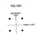
- these signal points are generated as impulses of real parts and imaginary parts. These impulses are generated at intervals (e.g., 2 ⁇ s) for which the reflected wave well vanishes.
- a zero point inserting unit 4-2 inserts a zero point signal between one transmission signal and the next transmission signal, and a roll-off filter (ROF1) limits the band to a band allowed in a power line carrier communication, and adjusts the wave shape.
- ROF1 roll-off filter
- the thus-output transmission signal is modulated by a modulation circuit (MOD), and is converted from a digital signal into an analog signal by a D/A converter (D/A). Thereafter, a low pass filter (LPF) extracts a signal of a low frequency band including a frequency band of the power line carrier wave, and outputs the extracted signal to a transmission line (TX-line).
- MOD modulation circuit
- D/A D/A converter
- LPF low pass filter
- a corresponding modem receives, via a reception line (RX-line), the transmission signal output to the transmission line (TX-line).
- a band pass filter (BPF) extracts only predetermined frequency band components
- an A/D converter (A/D) converts the signal into the digital signal.
- This digitalized reception signal is converted into a signal of a baseband by a demodulation circuit (DEM), and the wave shape of this signal is then adjusted by a roll-off filter (ROF2). Thereafter, the roll-off filter outputs the signal to a VCXO (Voltage Controlled Crystal Oscillator) type phase lock loop circuit (PLL VCXO).
- DEM demodulation circuit
- ROF2 roll-off filter
- PLL VCXO Voltage Controlled Crystal Oscillator
- This VCXO type phase lock loop circuit extracts the phase of the zero point, and provides the phase of the zero point as a sampling timing signal to the A/D converter (A/D) and to a clock (RX-CLK) distribution unit 4-3 of the reception unit.
- the zero point of the signal output from the roll-off filter (ROF2) of the reception unit is deleted by a zero point deleting unit 4-4, and the gain of the signal is then controlled to be a predetermined level by an automatic gain controlling unit (AGC). Thereafter, an automatic carrier phase controlling unit (CAPC) aligns the phase. Furthermore, a determining circuit (DEC) performs signal determination of the reception signal, and outputs a result of the signal determination to a vector difference circuit (difference N/G).
- AGC automatic gain controlling unit
- CAC automatic carrier phase controlling unit
- This vector difference circuit performs a vector difference operation on the signal corresponding to the signal output with the natural binary code (N) by the vector sum circuit (G/N) of the transmission unit. Then, this vector difference circuit returns the code to the Gray binary code (G), and outputs this signal to a descrambler (P/S DSCR).
- the descrambler (P/S DSCR) converts this parallel gray code into a serial signal to perform a descrambling process so as to obtain a reception signal (RD).
- a transmission clock distribution circuit (TX-CLK) distributes the transmission clock signal to the zero point inserting unit 4-2, the D/A converter (D/A), and other transmission circuit units.
- a reception clock (RX-CLK) distribution unit 4-3 extracts a reception clock signal from the VCXO type phase lock loop circuit (PLL VCXO), and distributes the extracted reception clock signal to the zero point deleting unit 4-4, and other reception circuit unit.
- the reception clock (RK-CLK) distribution unit 4-3 only passes the sampling timing signal that indicates the phase of the zero point and is extracted from the VCXO type phase lock loop circuit (PLL VCXO). This sampling timing signal is a mere symbol timing signal.
- Fig. 11 shows a configuration for negating reflected waves by multi-path equalizing according to the above Japanese Patent Application.
- a transmission signal is transmitted to a communication line 6-2 of a power line via a multi-path equalizing unit 6-1 in a pole transformer modem.
- the "n" number of reflected waves that return by the reflection at many branching points after respective delay times are combined, as shown in Fig. 2.
- a transferfunction of the communication line 6-2 is: 1/(1 + k 1 ⁇ Z -1 + k 2 ⁇ Z -2 + ⁇ + k n ⁇ Z -n ) .
- the multi-path equalizing unit 6-1 is configured so as to include a filter of a transfer function that is the inverse function of the transfer function of the communication line 6-2 so that the modem of the pole transformer can negate the reflected waves. That is, a FIR (Finite Pulse Response) filter whose transfer function is "1+C 1 ⁇ Z -1 +C 2 ⁇ Z -2 + ... +C n ⁇ Z -n )" is used as the filter of the multi-path equalizing unit 6-1.
- FIR Finite Pulse Response
- the multi-path equalizing unit 6-1 includes the "n" number of delay elements 6-11 corresponding to estimated maximum delay times, and a multiplying unit 6-12 that multiplies, by predetermined coefficients, respective output from the "n” number of the delay elements 6-11.
- the multi-path equalizing unit 6-1 further includes a coefficient correction unit 6-13 that calculates and corrects each coefficient by a least square method (LSM), and an error calculating unit 6-14 that compares the input transmission signal with the output transmission signal to output an error signal generated based on this comparison to the coefficient correcting unit 6-13.
- the multi-path equalizing unit 6-1 further includes a combining adding unit 6-15 that adds the combined signal to the transmission signal with the phase of the combined signal being opposite. This combined signal is generated by combining the respective signals that are produced by multiplying the output from the respective delay elements by the respective predetermined coefficients.
- the coefficient correcting unit 6-13 calculates the respective coefficients C 1 , C 2 , ... C n so as to minimize the error signal output from the error calculating unit 6-14.
- K 1 becomes equal to C 1
- K 2 becomes equal to C 2
- ... and K n becomes equal to C n , so that a transfer function of an entire transmission that includes the multi-path equalizing unit 6-1 and the communication line 6-2 becomes "1".
- the resonance points where the impedance becomes zero are not generated, so that it is possible to prevent a strong leak electromagnetic field from being generated.
- Fig. 12 shows another example of the pole transformer modem disclosed in the above Japanese Patent Application.
- This pole transformer modem has a function of providing impulse response intervals as described with reference to Figs. 6A through 6D and a function of negating reflected waves as described with reference to Figs. 8A through 8F.
- This configuration example of Fig. 12 is made such that the multi-path equalizing unit 6-1 is added to the transmission unit of the configuration of Fig. 9, an inverse fast Fourier transform unit 7-1 for performing orthogonal frequency division multiplexing (OFDM) and a guard time adding unit 7-2 are provided to the transmission unit of Fig. 9, and a high speed Fourier transform unit 7-3 for performing multiplex dividing by orthogonal frequency division multiplexing is provided to the reception unit of Fig. 9.
- OFDM orthogonal frequency division multiplexing
- the multi-path equalizing unit 6-1 compares the signal from the reception line (the receiving side) with the output signal (the output side), and calculates coefficients of the FIR filter such that the transfer function of the FIR filter becomes the inverse function of the transfer function of the multi-path power line. In this manner, the multi-path equalizing unit 6-1 eliminates the disadvantage produced by the multi-paths.
- the orthogonal frequency division multiplexing is a communication method in which the multiplexing transmission signals that are synchronizing orthogonal multiplexing digital modulated signals having a carrier wave frequency of a minimum frequency interval are consecutively transmitted.
- the transmission signals are multi-carrier modulated signals, so that a symbol period can be made to be longer compared with the case of transmitting a single carrier wave.
- a guard time adding unit 7-2 adds a guard interval on the time axis to reduce intersymbol interference even when there are the multi-paths as shown in Fig. 2. Accordingly, it is possible to reduce degrading in the transmission characteristics, and to suppress the transmission from being affected by a ghost.
- the symbol period is made to be longer by the guard interval that is determined based on an assumed delay time of the multi-path wave.
- symbol data of the guard interval part that is assumed to be affected by the intersymbol interference is not used, and the remaining symbol data is used to demodulate orthogonal frequency division multiplexing (OFDM) data, so that the influence by the noises can be removed.
- OFDM orthogonal frequency division multiplexing
- a data transmission method in which a leak electromagnetic field in the power line carrier system can be more effectively suppressed.
- Fig. 14 is a block diagram showing a part of the transmission unit of the above Japanese Patent Application shown in Fig. 12.
- a circuit configuration of Fig. 14 includes the inverse fast Fourier transform unit 7-1 that performs the orthogonal frequency division multiplexing (OFDM), and the inverse fast Fourier transform unit 7-1 performs signal transform from a frequency axis to a time axis on the signal including signal points generated by a signal point generating unit 4-1.
- a zero point inserting unit 4-2 inserts a zero point into the signal produced by the inverse fast Fourier transform unit 7-1, as shown in Fig. 7. Accordingly, as shown in Figs.
- the finite-difference function unit 6-1 as the multi-path equalizing unit 6-1 adds each signal having the opposite phase of the each reflected wave such that the added signal and the reflected wave negate each other.
- the reflected signals generated by the multi-paths can be effectively negated, so that it is possible to effectively suppress a leak electromagnetic field from being generated.
- one of the multi-paths in the finite-difference function unit 6-1 is shown in Fig. 14.
- the number of the zero points inserted by the zero point inserting unit 4-2 is determined by an environment to which the data transmission device is applied, types of the power lines for the power line carrier, the length of the power line, and the like. However, the number of points that is the number of carriers (carrier waves) in the inverse fast Fourier transform unit needs to be changed depending on the number of the inserted zero points. In other words, for example, when no zero point is inserted between two signal points, the inverse fast Fourier transform is performed with a process of 128 points (this. is assumed to be a standard condition).
- the signal transmission speed becomes the half of the signal transmission speed in the standard condition, so that the inverse fast Fourier transform needs to be performed by a process of 64 points that is half of the number in the standard condition.
- the inverse fast Fourier transform needs to be performed by a process of 32 points that is the one fourth of the number in the standard condition.
- the inverse fast Fourier transform needs to be performed by a process of 16 points that is one eighth of the number in the standard condition.
- the finite-difference function unit 6-1 generally has finite-difference function characteristics in Figs.- 15A and 15B that show a real component and a imaginary component. Accordingly, a signal amplitude is low in a low frequency range. A signal-to-noise ratio S/N is deteriorated in this region. The reason of this is as follows.
- the finite-difference function unit 6-1 shown in Fig. 14 has the characteristics as shown in Figs. 15 A and 15B.
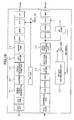
- Fig. 16 shows a configuration of a modem functioning as a data transmission device according to a first embodiment of the present invention.
- the circuit configuration in the first embodiment is basically the same as that shown in Fig. 12, but in the first embodiment, a copying unit 8-1 is provided instead of the zero point inserting unit 4-2 of the circuit configuration in Fig. 12. Furthermore, in the first embodiment, the inverse fast Fourier transform unit 7-1 and the guard time inserting unit 7-2 are provided in the downstream side of the copying unit 8-1 and the finite-difference function unit (multi-path equalizing unit) 6-1.
- the copying unit 8-1 copies signal points that are generated by the signal point generating unit 4-1.
- the inverse fast Fourier transform unit 7-1 performs the inverse Fourier transform on the thus-obtained signal in the frequency region. In this manner, as described later, the same advantage as that achieved by the zero point inserting is obtained on the time axis.
- the finite-difference function unit 6-1 is provided between the copying unit 8-1 and the inverse fast Fourier transform unit 7-1 so as to perform a vector multiplication process by the finite-difference function.
- the zero point inserting advantage that is obtained by signal point copying will be described with reference to Figs. 17A through 17H.
- the zero point inserting advantage is achieved by the copying unit 8-1 in the circuit configuration of Fig. 16.
- Fig. 17A when zero point data on the frequency axis is input in parallel with the data that is constituted by a set of signal points as shown in Fig. 17B, the frequency band becomes twice as long as the original frequency band.
- Fig. 17C the signal on the time axis is obtained.
- the copied data is input to the inverse fast Fourier transform function unit 7-1 as shown in Fig.
- the inverse fast Fourier transform unit 7-1 when the data constituted by 64 points is copied once, and the data corresponding to a total of 128 points on the frequency axis is input to the inverse fast Fourier transform unit 7-1, the signal in which one zero point is inserted between two signal points on the time axis is formed.
- the inverse fast Fourier transform unit may be configured so as to always perform the process corresponding to 128 points. Accordingly, it is possible to simplify the configuration of the inverse fast Fourier transform unit. 7-1.
- Fig. 18 shows the state where signal points generated by the signal point generating unit 4-1 of Fig. 16 are copied by the copying unit 8-1.
- the inverse fast Fourier transform for 64 points is shown in Fig. 16.
- One half of the frequency band in the inverse fast Fourier transform unit 7-1 is assigned to the original signal, and the other half of the frequency band in the inverse fast Fourier transform unit 7-1 is assigned to the copied signal.
- the frequency characteristics of the inverse fast Fourier transform are cosine square characteristics in terms of the inclination. Accordingly, it is possible to obtain the cosine square impulse response having a wide response width, and to obtain the output signal in which one zero point is inserted between two signal points.
- the finite-difference function unit 6-1 is provided between the copying unit 8-1 and the inverse fast Fourier transform unit 7-1.
- the finite-difference function unit 6-1 has characteristics as shown in Figs. 15A and 15B. Accordingly, when the signal on the frequency axis as shown in Fig. 18 is input to the finite-difference unit 6-1 from the copying unit 8-1, the vector multiplication is performed on this input signal by the finite-difference function shown in Figs. 15A and 15B. Next, the function of the finite-difference function unit 6-1 will be described.
- the finite-difference function unit 6-1 is not provided, and the output from the copying unit 8-1 is input directly to the inverse fast Fourier transform unit 7-1.
- the inverse fast Fourier transform unit 7-1 performs the inverse fast Fourier transform on the input signal thereof so as to produce the transformed signal shape on the time axis shown in Fig. 19.
- the original signal So and the zero point Z alternately appear in the signal on the time axis.
- the output from the copying unit 8-1 is input to the finite-difference function unit 6-1 where the finite-difference function process is performed. Thereafter, the output from the finite-difference function unit 6-1 is input to the inverse fast Fourier transform unit 7-1 where the inverse fast Fourier transform is performed to transform the input signal into the signal on the time axis shown in Fig. 20.
- the signal produced by the inverse fast Fourier transform unit 7-1 includes the inverted signal data Si. That is, the zero points Z are inserted by the copying unit 8-1, and are transformed into the inverted signal data Si. In other words, the original signal So and the inverted signal Si are alternately output as the cosine square impulse response.
- the number of times/of the copying is one, but the number of times of the copying by the copying unit 8-1 may be increased so that one or more zero points Z are inserted between the original signal and the inverted signal to appropriately adjust the leak electromagnetic field suppressing effect. This case will be described in the following.
- Fig. 21 shows an example in the inverse fast Fourier transform by 64 points.
- One fourth of the frequency band of the inverse fast Fourier transform unit 7-1 is assigned to the original signal, and each of the remaining three fourths of this frequency band is assigned to one copied signal.
- Fig. 22 shows the signal obtained by the inverse fast Fourier transform when the finite-difference function process is not performed by the finite-difference function unit 6-1.
- the process by the finite-difference function unit 6-1 causes one of the three zero points Z inserted between two signal points to become the inverted signal Si.
- two zero points Z are inserted between the original signal So and the inverted signal Si.
- Fig. 24 shows an example in the inverse fast Fourier transform by 64 points.
- one eighth of the frequency band of the inverse fast Fourier transform unit 7-1 is assigned to the original signal, and each of the seven other eighths of the frequency band is assigned to one copied signal.
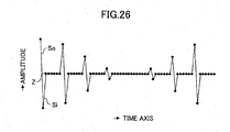
- Fig. 26 in the output signal from the inverse fast Fourier transform unit 7-1, six zero points Z are inserted between two signal points.
- Fig. 25 shows a wave shape obtained by the inverse fast Fourier transform when the finite-difference function process is not performed by the finite-difference function unit 6-1.
- the process by the finite-difference function unit 6-1 causes one of the seven zero points Z inserted by the copying process to become the inverted signal Si. Accordingly, as shown in Fig. 26, when the original signal So and the inverted signal Si of the original signal are alternately output as the cosine square impulse response, six zero points Z are inserted between the original signal So and the inverted signal Si.
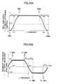
- the 100 percent cosine square characteristics (shown in Figs. 15A and 15B) in the inclination of the finite-difference function of the finite-difference function unit 6-1 are changed, the characteristics of the finite-difference function unit 6-1 have a flat region as shown in Figs. 27A and 27B, arid this flat region may be further widened. In this manner, it is possible to suppress degrading in a signal-to-noise ratio S/N at the low frequency side.
- the finite-difference function characteristics shown in Figs. 27A and 27B can be realized by decreasing a roll-off rate of the cosine square characteristics in the finite-difference function unit 6-1.
- the inverse fast Fourier transform with the same point number either in the case where one or more zero points are inserted between two signal points of the original signal without outputting the inverted signal as shown in Figs. 7, 19, 22, 25, and so on, or in the case where the signal inverted from the original signal by 180 degrees is output after the original signal as shown in Figs. 20, 23, 26, and so on. Accordingly, it is possible to simplify the configuration of the inverse fast Fourier transform unit 7-1.
- the vector multiplication is performed on the signal points as the inverse fast Fourier transform input. In this manner, it is possible to easily obtain the signal that is inverted by 180 degrees from the original signal.
- the roll-off rate of the cosine square characteristics may be decreased so as to minimize the signal attenuation in the used band. Thereby, it is possible to improve the signal-to-noise ratio S/N.
Landscapes
- Engineering & Computer Science (AREA)
- Computer Networks & Wireless Communication (AREA)
- Signal Processing (AREA)
- Power Engineering (AREA)
- Physics & Mathematics (AREA)
- Spectroscopy & Molecular Physics (AREA)
- Cable Transmission Systems, Equalization Of Radio And Reduction Of Echo (AREA)
- Digital Transmission Methods That Use Modulated Carrier Waves (AREA)
Applications Claiming Priority (2)
| Application Number | Priority Date | Filing Date | Title |
|---|---|---|---|
| JP2002246840A JP3986929B2 (ja) | 2002-08-27 | 2002-08-27 | 電力線搬送通信における漏洩電磁界抑圧送信方法及び漏洩電磁界抑圧送信装置 |
| JP2002246840 | 2002-08-27 |
Publications (1)
| Publication Number | Publication Date |
|---|---|
| EP1395013A1 true EP1395013A1 (de) | 2004-03-03 |
Family
ID=31492539
Family Applications (1)
| Application Number | Title | Priority Date | Filing Date |
|---|---|---|---|
| EP03015653A Withdrawn EP1395013A1 (de) | 2002-08-27 | 2003-07-17 | Verfahren und Vorrichtung zur Datenübertragung über eine Versorgungsleitungsträgerwelle |
Country Status (3)
| Country | Link |
|---|---|
| US (1) | US7286600B2 (de) |
| EP (1) | EP1395013A1 (de) |
| JP (1) | JP3986929B2 (de) |
Cited By (4)
| Publication number | Priority date | Publication date | Assignee | Title |
|---|---|---|---|---|
| US5932438A (en) * | 1994-04-21 | 1999-08-03 | Urquima, S.A. | Preparation of thaumatin sweeteners |
| EP1919111A4 (de) * | 2005-08-23 | 2010-03-24 | Mitsubishi Electric Corp | Drahtloses kommunikationssystem und kommunikationsvorrichtung |
| RU2467478C1 (ru) * | 2011-04-28 | 2012-11-20 | Михаил Анатольевич Ксенофонтов | Способ увеличения скорости передачи информации по линии электроснабжения |
| CN105516047A (zh) * | 2015-12-07 | 2016-04-20 | 湖南工业大学 | 自动抄表系统ofdm载波通信模块符号分组检测方法 |
Families Citing this family (6)
| Publication number | Priority date | Publication date | Assignee | Title |
|---|---|---|---|---|
| JP3925213B2 (ja) * | 2002-01-24 | 2007-06-06 | 富士通株式会社 | 漏洩電磁界抑圧方法並びに漏洩電磁界抑圧送信方法及び装置 |
| WO2007015317A1 (ja) * | 2005-08-02 | 2007-02-08 | Sumitomo Electric Industries, Ltd. | 送信機、受信機、通信方法及び送受信システム |
| US8162230B2 (en) * | 2006-10-17 | 2012-04-24 | Powerid Ltd. | Method and circuit for providing RF isolation of a power source from an antenna and an RFID device employing such a circuit |
| TW200835044A (en) * | 2006-10-17 | 2008-08-16 | Powerid Ltd | Method and circuit for providing RF isolation of a power source and an RF device employing such a circuit |
| US20100265041A1 (en) * | 2009-04-16 | 2010-10-21 | Powerid Ltd. | Rfid transponder |
| CN114025254B (zh) * | 2021-11-09 | 2024-01-23 | 国网四川省电力公司营销服务中心 | 不同支路电流的同步采样方法及系统 |
Citations (3)
| Publication number | Priority date | Publication date | Assignee | Title |
|---|---|---|---|---|
| EP1073241A2 (de) * | 1999-07-29 | 2001-01-31 | Matsushita Electric Industrial Co., Ltd. | Synchronisieren von Symbolen bei Mehrträgerübertragung |
| US20020001340A1 (en) * | 2000-03-29 | 2002-01-03 | Symmetricom, Inc. | Asymmetric digital subscriber line methods suitable for long subscriber loops |
| US20020114270A1 (en) * | 1994-12-15 | 2002-08-22 | Inmarsat Ltd | Multiplex communication |
Family Cites Families (9)
| Publication number | Priority date | Publication date | Assignee | Title |
|---|---|---|---|---|
| US6014412A (en) * | 1996-04-19 | 2000-01-11 | Amati Communications Corporation | Digital radio frequency interference canceller |
| US6035000A (en) * | 1996-04-19 | 2000-03-07 | Amati Communications Corporation | Mitigating radio frequency interference in multi-carrier transmission systems |
| US5995567A (en) * | 1996-04-19 | 1999-11-30 | Texas Instruments Incorporated | Radio frequency noise canceller |
| JP4536170B2 (ja) * | 1996-12-27 | 2010-09-01 | シャープ株式会社 | 撮像装置 |
| JP4272309B2 (ja) | 1998-10-29 | 2009-06-03 | パナソニック株式会社 | Ofdm通信装置 |
| US6657950B1 (en) * | 1999-02-19 | 2003-12-02 | Cisco Technology, Inc. | Optimal filtering and upconversion in OFDM systems |
| US6597745B1 (en) * | 1999-04-06 | 2003-07-22 | Eric M. Dowling | Reduced complexity multicarrier precoder |
| US6487253B1 (en) * | 1999-10-04 | 2002-11-26 | Cisco Technology, Inc. | OFDM channel estimation in the presence of interference |
| US6614864B1 (en) * | 1999-10-12 | 2003-09-02 | Itran Communications Ltd. | Apparatus for and method of adaptive synchronization in a spread spectrum communications receiver |
-
2002
- 2002-08-27 JP JP2002246840A patent/JP3986929B2/ja not_active Expired - Lifetime
-
2003
- 2003-07-16 US US10/620,819 patent/US7286600B2/en not_active Expired - Fee Related
- 2003-07-17 EP EP03015653A patent/EP1395013A1/de not_active Withdrawn
Patent Citations (3)
| Publication number | Priority date | Publication date | Assignee | Title |
|---|---|---|---|---|
| US20020114270A1 (en) * | 1994-12-15 | 2002-08-22 | Inmarsat Ltd | Multiplex communication |
| EP1073241A2 (de) * | 1999-07-29 | 2001-01-31 | Matsushita Electric Industrial Co., Ltd. | Synchronisieren von Symbolen bei Mehrträgerübertragung |
| US20020001340A1 (en) * | 2000-03-29 | 2002-01-03 | Symmetricom, Inc. | Asymmetric digital subscriber line methods suitable for long subscriber loops |
Cited By (6)
| Publication number | Priority date | Publication date | Assignee | Title |
|---|---|---|---|---|
| US5932438A (en) * | 1994-04-21 | 1999-08-03 | Urquima, S.A. | Preparation of thaumatin sweeteners |
| EP1919111A4 (de) * | 2005-08-23 | 2010-03-24 | Mitsubishi Electric Corp | Drahtloses kommunikationssystem und kommunikationsvorrichtung |
| US8265179B2 (en) | 2005-08-23 | 2012-09-11 | Mitsubishi Electric Corporation | Wireless communication system and communication apparatus |
| RU2467478C1 (ru) * | 2011-04-28 | 2012-11-20 | Михаил Анатольевич Ксенофонтов | Способ увеличения скорости передачи информации по линии электроснабжения |
| CN105516047A (zh) * | 2015-12-07 | 2016-04-20 | 湖南工业大学 | 自动抄表系统ofdm载波通信模块符号分组检测方法 |
| CN105516047B (zh) * | 2015-12-07 | 2018-10-09 | 湖南工业大学 | 自动抄表系统ofdm载波通信模块符号分组检测方法 |
Also Published As
| Publication number | Publication date |
|---|---|
| JP3986929B2 (ja) | 2007-10-03 |
| US7286600B2 (en) | 2007-10-23 |
| US20040042391A1 (en) | 2004-03-04 |
| JP2004088421A (ja) | 2004-03-18 |
Similar Documents
| Publication | Publication Date | Title |
|---|---|---|
| JP3427381B2 (ja) | 雑音キャンセル方法及び装置 | |
| KR100655345B1 (ko) | 잡음 제거 방법 및 장치 | |
| Faulkner | The effect of filtering on the performance of OFDM systems | |
| US8571118B2 (en) | Transmission line directional coupling | |
| US5757854A (en) | In-band on-channel digital broadcasting | |
| EP0847643B1 (de) | Verfahren zur vereinfachung der demodulation in einem mehrfachträger-übertragungssystem | |
| EP1109328B1 (de) | DSL-Übertragungsystem mit Fernnebensprechkompensation | |
| JP3387919B2 (ja) | データ伝送方法及び装置 | |
| EP1395013A1 (de) | Verfahren und Vorrichtung zur Datenübertragung über eine Versorgungsleitungsträgerwelle | |
| EP1333593A1 (de) | Versorgungsvertrangungstechnik | |
| US20020186715A1 (en) | Master-slave data transmission in orthogonal frequency-division multiplexing | |
| CN100449972C (zh) | 正交频分复用信号解调装置 | |
| JP3747415B1 (ja) | 多重伝送装置及び多重伝送方法 | |
| Daikoku | Asynchronous Demodulation Method for Four SS Barranged on Frequency Axis in Mobile Radio Path using Hilbert Transform | |
| GB2457967A (en) | Acoustic multicarrier OFDM for shallow water communication |
Legal Events
| Date | Code | Title | Description |
|---|---|---|---|
| PUAI | Public reference made under article 153(3) epc to a published international application that has entered the european phase |
Free format text: ORIGINAL CODE: 0009012 |
|
| AK | Designated contracting states |
Kind code of ref document: A1 Designated state(s): AT BE BG CH CY CZ DE DK EE ES FI FR GB GR HU IE IT LI LU MC NL PT RO SE SI SK TR |
|
| AX | Request for extension of the european patent |
Extension state: AL LT LV MK |
|
| 17P | Request for examination filed |
Effective date: 20040823 |
|
| AKX | Designation fees paid |
Designated state(s): DE FR GB |
|
| 17Q | First examination report despatched |
Effective date: 20080917 |
|
| STAA | Information on the status of an ep patent application or granted ep patent |
Free format text: STATUS: THE APPLICATION IS DEEMED TO BE WITHDRAWN |
|
| 18D | Application deemed to be withdrawn |
Effective date: 20090128 |