EP1395695B1 - Lave-linge entierement automatique et procede de commande de celui-ci - Google Patents
Lave-linge entierement automatique et procede de commande de celui-ci Download PDFInfo
- Publication number
- EP1395695B1 EP1395695B1 EP02731007A EP02731007A EP1395695B1 EP 1395695 B1 EP1395695 B1 EP 1395695B1 EP 02731007 A EP02731007 A EP 02731007A EP 02731007 A EP02731007 A EP 02731007A EP 1395695 B1 EP1395695 B1 EP 1395695B1
- Authority
- EP
- European Patent Office
- Prior art keywords
- shaft
- washing machine
- coupling
- full automatic
- automatic washing
- Prior art date
- Legal status (The legal status is an assumption and is not a legal conclusion. Google has not performed a legal analysis and makes no representation as to the accuracy of the status listed.)
- Expired - Lifetime
Links
Images














Classifications
-
- D—TEXTILES; PAPER
- D06—TREATMENT OF TEXTILES OR THE LIKE; LAUNDERING; FLEXIBLE MATERIALS NOT OTHERWISE PROVIDED FOR
- D06F—LAUNDERING, DRYING, IRONING, PRESSING OR FOLDING TEXTILE ARTICLES
- D06F37/00—Details specific to washing machines covered by groups D06F21/00 - D06F25/00
- D06F37/30—Driving arrangements
- D06F37/40—Driving arrangements for driving the receptacle and an agitator or impeller, e.g. alternatively
Definitions
- the present invention relates to a full automatic washing machine, and more particularly, to a new driving mechanism, and washing and spinning methods thereof, in a full automatic washing machine, in which washing and rinsing are made by a slow pulsator, and spinning is made by fast spinning tub.
- the washing machine in general removing various dirt stuck to clothes, beddings, and the like by using softening action of detergent, friction caused by water circulation coming from rotation of the pulsator, and impact given to laundry by the pulsator, carries out washing after sensing amount and kind of the laundry by sensors, to make automatic setting of a washing method, and supplying water to proper level according to the amount and kind of the laundry.
- US 5 887 458A discloses a washing machine having a power switching device comprising of a rotatable cam lever and first and second clutch levers.
- An object of the present invention devised for solving the foregoing various problems, is to provide a full automatic washing machine having a driving mechanism in which a stable rotation power transmission from a driving part with a stator and a rotor to a pulsator, or a spinning tub is change-over controlled positively without noise, and within a short time period.
- Another object of the present invention is to provide a control method which can release a seizure caused by an inserted coupling in various situations of after water supply, before progressing a main washing, at finish of washing, before progressing a main spinning, and the like in a full automatic washing machine having a new form of driving mechanism in which a stable rotation power transmission from a driving part with a stator and a rotor to a pulsator, or a spinning tub is change-over controlled positively without noise, and within a short time period.
- a full automatic washing machine including the combination of the features of claim 1.
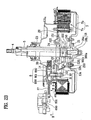
- FIG. 1 illustrates a section of a full automatic washing machine having a clutch mechanism applied thereto in accordance with a first preferred embodiment of the present invention schematically
- FIGS. 2A - 2C illustrate sections of key parts each showing an operation of a clutch mechanism in accordance with a first preferred embodiment of the present invention
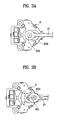
- FIG. 3A illustrates a bottom view across a line I-I in FIG. 2A
- FIG. 3B illustrates a bottom view across a line II-II in FIG. 2B .
- the full automatic washing machine in accordance with a first preferred embodiment of the present invention includes a spinning tub 2 rotatably fitted to an inside of an outer tub 1 of a main body, a pulsator 3 fitted to an inside of the spinning tub 2 rotatable independent from the spinning tub 2, a spinning shaft 5 rotatably held in a shaft holding bearing case 20 for transmission of a rotating power to the spinning tub 2, a washing shaft 6 for transmission of the rotating power to the pulsator 3, a motor 7 having a stator 7a and a rotor 7b in which the rotor 7b rotates as the stator 7a is provided with an electric power, and a clutch mechanism for switching a power transmission path of the motor 7 to the washing shaft 6 or the spinning shaft 5.
- the clutch mechanism includes a clutch motor 6 fitted under the outer tub 1, a cam 600 coupled with a driving shaft 602 of the clutch motor 6, a lever guide 30 fixed to the shaft holding bearing case 20, a lever 8 having a recess 800 with a sloped surface 801, and a flat surface 802 horizontally extended from a lower end of the sloped surface 801 for making a linear movement guided by the lever guide 30 when the clutch motor 6 is turned on/off, a connecting rod 17 between the cam 600 and lever 8 of the clutch motor 6 for pulling the lever 8 toward the clutch motor side when the clutch motor 6 is turned on, a return spring 14 having one end fixed to a fore end of the lever guide 30, and the other end fixed to a fixed projection from one side of the lever 8, for providing a return force to the lever 8, a hollow mover 9 for being brought into contact with the recess 800 with the sloped surface 801 of the lever 8 when the clutch motor 6 is turned off, and moving down along the sloped surface 801 until being positioned under the flat surface 802 when the clutch motor 6
- the clutch motor 6 is a geared motor for transferring a power to the driving shaft 602 coupled to the cam 600 at a reduced speed by means of gears.
- the connecting rod 17 has one end coupled to the cam 600 and the other end hinge coupled to the lever 8.
- the coupling 15 includes an upper part having gear teeth 151 formed thereon for engagement with the gear teeth 221 on the coupling stopper 22, and an inside circumferential surface having a serration 150 formed therein for engagement with the serration in the spinning shaft 5 and a serration 161b in an outside circumferential surface in an upper part of an inner connector 16b of the connector assembly 16.
- the connector assembly 16 includes an outer connector 16a of a resin fastened to the rotor with bolts, and an inner connector 16b injection molded of a metal as a unit with the outer connector 16a at an inside thereof having a serration 160b in an inside circumferential surface thereof for engagement with the serration in a lower part of the washing shaft 6, and a serration 161b in an outside circumferential surface of an upper part thereof exposed to an outside of the outer connector 16a.
- the inner connector 16b is formed of an aluminum alloy sintering, for improvement of strength.
- torsion spring 13a on the support bracket 220 of the coupling stopper 22 the fixing pin 12b is coupled thereto as an elastic member for providing a rotational force such that the movable rod 12 rotates in a clockwise direction around the fixing pin 12b when the clutch motor 6 is turned off.
- Unexplained reference symbol 23 refers to an upper shaft support bearing.
- the foregoing clutch mechanism in accordance with a preferred embodiment of the present invention maintain a state as shown in FIGS. 2B and 3B before washing is started as it is a turned off state when there is no power provided to the clutch motor 6.
- the mover 9 rests in the recess 800 with the sloped surface 801 of the lever 8, and the coupling 15 is at a lowest position.
- the mover 9 When the mover 9 moves down following the movement of the lever 8, the mover 9 compresses the buffer spring 11, according to which the plunger 10, fitted to move up and down along the guide groove of the mover 9, also moves down.
- the movable rod 12 hinge coupled to the plunger 10 rotates in a counter clockwise direction when the drawing is seen from above around the fixing pin 12b passed through the support bracket 220 of the coupling stopper 22 fixed to the underside of the shaft bearing holding case 20.
- the movable rod 12 hinge coupled to the plunger 10 rotates in a clockwise direction when the drawing is seen from above around the fixing pin 12b fitted to pass through the support bracket 220 of the coupling stopper 22 fixed to the underside of the shaft holding bearing case 20.
- the coupling moves down by gravity and the pushing force of the compression spring 40, to disengage the gear teeth 151 of the coupling 15 from the gear teeth 221 of the coupling stopper 22. (see FIGS. 2B and 4B ).
- the serration 150 in the inside circumferential surface of the coupling 15 is engaged both with the serration 161b in the outside circumferential surface of the upper part of the inner connector 16b coupled to the washing shaft 6, and the serration in the lower part of the spinning shaft 5, such that both the washing shaft 6 and the spinning shaft 5 rotate at a high speed when the rotor 7b rotates at a high speed, to progress the spinning.
- positions of the gear teeth 221 are fixed as the coupling stopper 22 is fixed to the shaft holding bearing case 20, positions of the gear teeth 151 vary when the gear teeth are standstill as the coupling 15 is rotatable with the spinning shaft 5.
- the coupling 15 slightly engaged with the serration 161 b in the outside circumferential surface of the upper part of the inner connector 16b, rotates until the crests and spaces of the teeth meet, when the gear teeth 151 of the coupling 15 and the gear teeth 221 of the coupling stopper 22 engage smoothly as the buffer spring 11 between the mover 9 and the plunger 10 in the clutch mechanism of the present invention pushes, to free the momentary seizure of the coupling 15.
- the lower part of the washing shaft is formed to be square, and the inside of the inner connector 16b is formed to be a square hollow fit to the square shaft, so that the square shaft and the square hollow are shaft coupled.
- the foregoing embodiment shows a case when the connecting rod 17 and the lever 8 are hinge coupled, if the coupling of the connecting rod 17 with the lever 8 is not the hinge coupling, it is required that the connecting rod is formed of a flexible material.
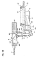
- FIGS. 5A - 5B illustrate sections of key parts each showing an operation of a clutch mechanism in accordance with a second preferred embodiment of the present invention
- FIGS. 6A - 6B illustrate enlarged views of FIGS. 5A - 5B respectively
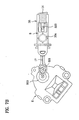
- FIG. 7A illustrates a bottom view across a line I-I in FIG. 5A
- FIG. 7B illustrates a bottom view across a line II-II in FIG. 5B .
- the full automatic washing machine in accordance with a second preferred embodiment of the present invention also includes a washing and spinning tub 2 rotatably fitted to an inside of an outer tub 1, a pulsator 3 fitted to an inside of the spinning tub 2 so as to be rotatable independent from the spinning tub 2, a spinning shaft 5 rotatably held by a shaft holding bearing case 20 (see FIG.
- a washing shaft 4 for transmission of the rotating power to the pulsator 3
- a BLDC motor 7 having a stator 7a and a rotor 7b for rotating the rotor 7b as electric power is provided to the stator 7a
- a clutch mechanism for switching a power transmission path from the BLDC motor 7 either to the washing shaft 4 or to the spinning shaft 5 in correspondence to a washing cycle, or a spinning cycle.
- the clutch mechanism includes a clutch motor 6 fitted under the outer tub 1, a cam 600 coupled with a driving shaft 602 of the clutch motor 6, a lever guide 30 fixed to the shaft holding bearing case 20, a lever 8 having a recess 800 with a sloped surface 801, and a flat surface 802 horizontally extended from a lower end of the sloped surface 801 for making a linear movement guided by the lever guide 30 when the clutch motor 6 is in operation, a connecting rod 17 between the cam 600 and lever 8 of the clutch motor 6 for pulling the lever 8 toward the clutch motor side when the clutch motor 6 is turned on, a return spring 14 having one end fixed to a fore end of the lever guide 30, and the other end fixed to a catch projection at one side of the lever 8, for providing a return force to the lever 8, a hollow cylindrical mover 9 for being in contact with the recess 800 with the sloped surface 801 of the lever 8 in spinning, and moving down along the sloped surface 801 until being positioned under the flat surface 802 in switching to a washing mode, a plunger 10
- the clutch motor 6 is a geared motor having a reduction gear therein for transferring a power to the driving shaft 602 coupled to the cam 600 at a reduced speed.
- the connector assembly 16 includes an outer connector 16a of a resin fastened to the rotor with bolts, and an inner connector 16b injection molded of a metal as a unit with the outer connector 16a at an inside thereof having a serration 160b in an inside circumferential surface thereof for engagement with the serration in a lower part of the washing shaft 6, and a serration 161b in an outside circumferential surface of an upper part thereof exposed to an outside of the outer connector 16a.
- the inner connector 16b is formed of an aluminum alloy sintering, for improvement of strength.
- the outer connector 16a has an annular elastic member seat 162a in a center part of a top surface, and a rubber ring 18, the elastic member, is seated on the seat 162a.
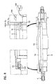
- FIG. 8 illustrates an enlarged view showing structures of a washing shaft and a spinning shaft in FIG. 5A .
- the spinning shaft 5 includes a lower shaft part 5b with a large inside diameter, and an upper shaft part 5a press fit inside of an upper part of the lower shaft part 5b.
- An upper part of the lower shaft part 5b is held by the upper shaft holding bearing 23 which holds the spinning shaft 5.
- the washing shaft 4 has a step 400 in a lower part thereof, and the inner connector 16b has a step fit to the step 400 on the washing shaft 4 in an inside circumferential surface thereof for defining a fastening position when the connector 16b is coupled to the lower part of the washing shaft 4 and fastened with a nut.
- the gap G1 between the inner connector 16b and the spinning shaft 5 is formed smaller than a gap G2 between a ball bearing 51 supporting a lower part of the washing shaft 4 in a radial direction and a C-ring 52.
- the sealing member 53 has at least three lips 530 provided at an inside thereof for securing a sealing reliability.
- FIG. 9 illustrates an enlarged view of 'A' part in FIG. 5A .
- the sealing member 54 has at least four lips 540a fitted to an inside thereof and at least three lips 540b fitted to an outside thereof, for securing a sealing reliability.
- FIG. 10 illustrates a section for explaining a process for assembling key parts of a clutch mechanism in accordance with a second preferred embodiment of the present invention
- FIG. 11 illustrates a perspective view of a state after assembly of one in FIG. 10 .
- the plunger 10, to be inserted in the mover 9, has a projection 101 from an outside circumference of an upper part thereof for preventing the plunger 10 from falling off the mover 9 when the plunger 10 and the mover 9 are assembled with the buffer spring 11 inserted between the plunger 10 and the mover 9.
- the plunger 10, to be inserted in the mover 9 has a radial direction projection 101 from an outside circumference of an upper part thereof, if the plunger 10 is pressed into the mover 9 in a state the compression spring, the buffer spring 11, is inserted in an outside circumferential surface of the plunger 10, such that the projection 101 from the plunger 10 is inserted in a guide long hole 901 formed in one side of an outside circumferential surface of the mover 9, the falling off of the plunger 10 from the mover 9 can be prevented, as a lower end of the projection 101 is caught at a lower end of the guide long hole 901 in the mover 9 even if the mover 9 is pushed upward by a restoring force of the buffer spring 11.
- the mover 9 has guide ribs 902 on an outside circumferential surface thereof each extended along an axis direction, and the lever guide 30, the mover 9 is to be inserted therein, has guide grooves 30a-1 in an inside circumferential surface of a guide part 30a formed to fit to the guide ribs 902 for guiding linear movement of the mover 9.
- the mover 9 has a sloped surface at a top part thereof in correspondence to the sloped surface 801 of the lever 8, for making the mover 9 to move in a vertical direction when the lever 8 moves in a horizontal direction.
- the return spring 14 has one end in a form of a hook for hooking a hooking projection 803 of the lever 8, and the other end wound to a larger diameter D2 than the other part of diameter D1 for being caught at a rear end of the lever guide 30, and thereby fixing a position of the return spring 14.
- the connecting rod 17 has one end coupled with the cam 600, and the other end hinge coupled with the lever 8, and there is stopper 805 at a bottom of one end of the lever 8, the connecting rod is coupled thereto, for defining an insertion position of the lever 8 in the lever guide when a restoration force of the return spring 14 is applied thereto.
- FIGS. 5A - 6B , 10 , and 11 there is a projection 222 from an outer side of the coupling stopper 22 to be positioned between the plunger 10 and the support bracket 220 of the coupling stopper 22.
- a tension spring 13b between the projection 222 and the connecting part 12a for providing a rotation force so that the movable rod 12 rotates in a clockwise direction around the fixing pin 12b.
- a fore end of the movable rod 12 to come into contact with the underside of the flange part 152 of the coupling 15 is rounded for reducing friction.
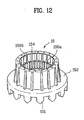
- FIG. 12 illustrates a perspective view of the coupling 15, including a flange part 152 in an upper part of a cylindrical body thereof extended in a radial direction, gear teeth 151 at an edge of a top surface of the flange part 152 along a circumference thereof for engagement with the gear teeth 221 of the coupling stopper 22, and serrations 150a, and 150b in an inside surface thereof for engagement with the serration in the spinning shaft 5, and the serration 161b in the outside circumferential surface of the upper part of the inner connector 16b of the connector assembly 16.
- Pitches of the serrations 150a and 150b in the inside surface of a body of the coupling 15 are made to have different modules from each other, wherein the serrations 150a and 150b are called as an upper serration 150a and a lower serration 150b with reference to a top of the inner connector 16b at a time the coupling 15 moves down fully, and engages with the inner connector 16b.
- the pitches of the serrations in the inside surface of a body of the coupling 15 are made such that the module of the serration 150b positioned in a lower part with reference to the top of the inner connector 16b when engaged is greater.
- a module ratio of the serration 150a in the upper part of the inside of the body of the coupling 15 to the serration 150b in a lower part thereof is 1:1.5.
- the lower ends of the rounded lower side serration 150b are rounded to be involute profile surfaces for easy clutching with the serration of the inner connector 16b.
- a region lower ends of the upper side serration 150a and bottom lands of the lower side serration 150b are met therein is rounded to reduce rapid sectional area transition for increasing a strength against a torsional stress.
- the projections 154 from a lower end of the body of the coupling 15 along a circumference thereof serve to reduce a contact area of the coupling 15 with the rubber ring 18, the elastic member, seated in the elastic member seat 162a in the outer connector 16a.
- FIG. 13 illustrates a perspective view of a rubber ring
- FIG. 14 illustrates a section of one in FIG. 13 .
- the rubber ring 18 includes an elastic rib 180 under an inside ring thereof having a dimension slightly smaller than an outside diameter of the inner connector 16b, an annular groove 181 in a lower surface thereof on an outer side, and in a radial direction of the elastic rib 180, for providing.an allowance of radial direction deformation of the elastic rib 180, and a groove 182 in a part in contact with the underside of the coupling 15 on the rubber ring for preventing the rubber ring from sticking to the underside of the coupling 15, and moving together with the coupling 15, and providing a cushion.
- the groove 182 in the upper surface of the coupling 15 is formed by annular ribs 183 spaced in a radial direction.
- the clutch mechanism in accordance with a second preferred embodiment of the present invention is in a turned off state when no power is provided to the clutch motor 6, when the coupling 15 is in a moved down state as shown in FIGS. 5B and 6B .
- the mover 9 rests in the recess 800 with the sloped surface 801 of the lever 8, and the coupling 15 is at the lowest position.
- the movable rod 12, hinge coupled to the plunger 10 rotates in a counter clockwise direction when the drawing is seen from above around the fixing pin 12b at the one point of the intermediate part passing through the support bracket 220 of the coupling stopper 22 fixed to the underside of the shaft holding bearing case 20.
- the coupling 15 decouples from the connector assembly 16, allowing rotation of the washing shaft 4 only, when the rotor 7b rotates.
- the turned off state of the clutch motor 6 held when the washing machine is switched to the washing mode to progress washing is made available by the system and operation of the clutch motor of the present invention.
- the system and operation of the clutch motor of the present invention which can hold a position of the cam 600 even in a turned off state will be explained in detail, later.
- the coupling 15 moves down by gravity and the restoration force of the compression spring 40, to disengage the gear teeth 151 of the coupling 15 from the gear teeth 221 of the coupling stopper 22.
- the serrations 150a and 150b in the inside circumferential surface of the coupling 15 respectively engage with the serration 161b in the outside circumferential surface of the upper part of the inner connector 16b coupled to the washing shaft 4, and the serration in the lower part of the spinning shaft 5, such that both the washing shaft 4 and the spinning shaft 5 rotate at a high speed when the rotor 7b rotates at a high speed, to progress the spinning.
- positions of the gear teeth 221 are fixed as the coupling stopper 22 is fixed to the shaft holding bearing case 20, positions of the gear teeth 151 vary when the gear teeth are standstill as the coupling 15 is rotatable with the spinning shaft 5.
- the coupling 15 slightly engaged with the serration 161b in the outside circumferential surface of the upper part of the inner connector 16b, rotates until the crests of the coupling and spaces of the teeth of the inner connector meet, when the gear teeth 151 of the coupling 15 and the gear teeth 221 of the coupling stopper 22 engage smoothly as the buffer spring 11 between the mover 9 and the plunger 10 in the clutch mechanism of the present invention pushes, to free the momentary seizure of the coupling 15.
- the lower part of the washing shaft is formed to be square, and the inside of the inner connector 16b is formed to be a square hollow fit to the square shaft, so that the square shaft and the square hollow are shaft coupled.
- the foregoing second embodiment shows a case when the connecting rod 17 and the lever 8 are hinge coupled, if the coupling of the connecting rod 17 with the lever 8 is not the hinge coupling, it is required that the connecting rod is formed of a flexible material.
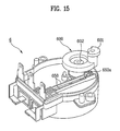
- FIG. 15 illustrates a perspective view of a clutch motor
- FIG. 16 illustrates a disassembled perspective view of one in FIG. 13 , referring to which a structure and operation of the clutch motor of the present invention will be explained.
- the clutch motor 6 of the present invention has the cam 600 directly coupled to the driving shaft 602, such that the cam 600 rotates at an angular speed the same as the driving shaft 602, and the cam 600 also stops at a position the driving shaft 602 stops.
- the clutch motor 6 of the present invention a modified version of a drain motor used in general for driving a drain valve, has an identical motor driving part system, inclusive of the rotor and the stator.
- the clutch motor 6 of the present invention being an assembled structure having no slip between the cam 600 and the driving shaft 602 at all, prevents the quick return, and has a range of cam groove formation angle in the cam 600 different from the related art drain motor cam.
- the formation angle of the cam groove in the cam 600 of the clutch motor of the present invention may be set within a range of 90 degrees to 250 degrees, and preferably within a range of 180 degree to 210 degrees.
- the cam 600 can not rotate as far as the driving shaft does not rotate. Since the quick return of cam 600 is prevented even when the clutch motor 6 is turned off due to a torque required for rotation of the driving shaft greater and a restoration force of the return spring 14, noise of impact caused by the quick return of the coupling 15, the lever 8, and the like is prevented, implementing low noise in clutch operation.
- the clutch motor 6 of the present invention requires no sustaining power in carrying out a macerating course, or the like, that takes a long time period, since the cam 600 also stops at a position the driving shaft 602 stops.
- FIGS. 17A - 17C illustrate operative relations of a driving cam and a switch in a clutch motor of the present invention schematically, wherein FIG. 17A illustrates a cam and switch state at a washing mode holding point, FIG. 17B illustrates a cam and switch state just before switching to a spinning mode, and FIG. 17C illustrates a cam and switch state at an initial point.
- FIG. 18 illustrates a timing diagram showing operative relations between a clutch motor, cam, and switch in the present invention. Referring to the foregoing drawings, the operative relations of the cam and the switch of the clutch motor will be explained.
- the switch 650 In a state the cam 600 is at an initial point, the switch 650 is in a turned off state.
- the state the cam 600 is at an initial point is a state a rod connecting shaft 601 of the cam 600 is directed to an initial point.
- the switch 650 When the rotation angle of the cam 600 reaches to a preset angle (for an example, 150 degrees) from the initial point, the switch 650 is turned on as the projection 650a of the switch 650 comes out of the cam groove surface 600a of the cam 600.
- a preset angle for an example, 150 degrees
- a turn on state maintenance time period of the clutch motor 6 can be calculated by dividing a rotation angle (i.e., 20 degrees) from a switch 650 turn on point to the holding point with one rotation period, since the one rotation period of the clutch motor 6 is constant.
- the clutch motor 6 is turned on again to turn the cam 600 in the clockwise direction, when the switch is in a turned on state until the cam 600 passes a point (a point 158 degrees from the holding point in the clockwise direction) 328 degrees from the initial point in the clockwise direction when the projection 650a of the switch 650 is on the cam groove surface 600a, to turn the switch 650 off as contact points thereof come apart (see FIG. 17B ).
- a turn on state maintenance time period of the clutch motor 6 can be calculated by dividing a rotation angle (i.e., 32 degrees) from a switch 650 turn off point to the initial point with one rotation period, since one rotation period of the clutch motor 6 is constant.
- FIG. 19 illustrates a timing diagram showing operation of a BLDC motor and a clutch motor at an initial stage of washing in a washing machine in accordance with a preferred embodiment of the present invention, referring to which the decoupling of the coupling 15 to be made before and after the switching from the spinning mode to the washing mode will be explained.
- moving up of the coupling 15 may be seized since the serrations 150a and 150b in the inside circumferential surface of the coupling 15 receive opposite facial pressures from the serration in the lower part of the spinning shaft 5 and the serration 161b in the upper part of the inner connector 16b as the spinning shaft 5 and the inner connector 16b engaged with the coupling 15 set in opposite directions in a previous stop.
- the step for alternating rotation of the BLDC motor 7 is carried out, for preventing the seize of the upward movement of the coupling 15, before carrying out the step of moving up the coupling 15 to the washing mode position by turning on the clutch motor 6 after the water supply for washing.
- rotation direction of the BLDC motor 7 is alternated for a time period at rotation angles smaller than a rotation angle in the washing.
- the rotation direction of the BLDC motor 7 is also alternated for a time period at short intervals before the main washing having regular reversing periods is carried out for prevention of overload on the system at an initial stage of washing.
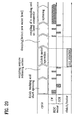
- FIG. 20 illustrates a timing diagram showing operation of a BLDC motor and a clutch motor at finish of washing and at an initial stage of spinning in a washing machine in accordance with a preferred embodiment of the present invention.
- move down of the coupling 15 may be seized when the clutch motor 6 is put into operation because there may be opposite facial pressures to the gear teeth 151 of the coupling 15 and the gear teeth 221 of the coupling stopper 22 caused by setting of the coupling 15 to the coupling stopper 22 in a seized state in the previous stop.
- the step of alternating a rotation direction of the BLDC motor 7 is carried out for releasing the coupling 15 from the seizure just before the step of moving down the coupling 15 to the spinning mode position is carried out by turning on the clutch motor 6 for switching to the spinning mode after finishing the washing.
- the BLDC motor 7 is controlled to alternate a rotation direction for a time period at rotation angles smaller than a rotation angle in washing.
- FIG. 21 illustrates a flow chart showing the steps of a process for controlling a clutch motor in change over of a washing mode in accordance with a preferred embodiment of the present invention
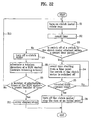
- FIG. 22 illustrates a flow chart showing the steps of a process for controlling a clutch motor in change over of a spinning mode in accordance with a preferred embodiment of the present invention.
- water is supplied for the washing (a first step), when the cam 600 of the clutch motor is at the initial point, with the switch 650 in a turned off state.
- the clutch motor 6 is turned on, to rotate the cam 600 (a second step), and, on the same time with this, a time period is counted (a third step).
- step 4 attainment of change to a turned on state of the switch 650 of the clutch motor 6 within a preset time period following rotation of the cam 600 is checked continuously starting from the time counting (step 4).
- step 6 reach of a counted pulse number to a preset pulse number is determined (step 6), and, when the number of pulses is reached to the preset pulse number as a result of the determination, the clutch motor 6 is turned off for holding a cam position (step 7).
- the cam 600 is at a setting point for carrying out the washing mode.
- step 4 in a case the change to a turned on state of the switch 650 is not attained even if the preset time period is exceeded, the clutch motor 6 is turned off (step 8), and a rotation direction of the BLDC motor is alternated for a time period at short intervals, to make a seizure releasing action (step 9).
- a number of the seizure releasing actions made by the BLDC motor 7 is checked (step 1.0), to return to the step 2 to turn on the clutch motor 6 again to drive the cam 600 when the number of the seizure releasing actions made by the BLDC motor 7 is failed to reach to the preset number of seizure releasing actions (step 11), and, contrary to this, if the number of the seizure releasing actions made by the BLDC motor 7 is reached to the preset number of seizure releasing actions, an error is displayed on a display part (not shown), and the washing machine is stopped (step 12).
- a time period required for changing the switch 650 in the clutch motor 6 to the turned on state, when the clutch motor 6 is turned on after the water supply is finished, is set to be within five seconds for application to 50Hz or 60Hz of a frequency of a rated voltage provided to the clutch motor 6 in common. That is; a time period required for rotating the cam 600 of the clutch motor 6 one turn is set to be 12 seconds when the frequency is 50Hz, and 10 seconds when the frequency is 60Hz due to a speed reduction by a reduction gear in the clutch motor 6.
- the time period required for changing the switch 650 in the clutch motor 6 to the turned on state is set to be five second, for application both to 50Hz case, and 60Hz for rotation as much as this angle.
- time period required for one turn of the cam 600 is applicable to a process for controlling the clutch motor 6 in spinning, explained later.
- the clutch motor 6 When the washing is finished, the clutch motor 6 is in a turned off state, and the switch 650 in the clutch motor 6 is in a turned on state as the cam 600 is at the washing holding point.
- the clutch motor 6 is turned on to rotate the cam 600 at first in a state the switch 650 is turned on when the cam 600 of the clutch motor 6 is at the holding point (step 1), and, on the same time with this, a time period is counted (step 2).
- step 3 attainment of change to a turned off state of the switch 650 of the clutch motor 6 within a preset time period following rotation of the cam 600 is checked continuously starting from the time counting (step 3).
- a driving time of the clutch motor 6 is counted newly starting from a time right after the change of the switch 650 to the turned off state (step 4).
- step 5 reach of a counted driving time of the clutch motor 6 to a preset time is determined (step 5), and, when the newly counted driving time period of the clutch motor 6 starting from a time right after the change of the switch 650 to the turned off state is reached to the preset time period as a result of the determination, the clutch motor 6 is turned off for holding a cam position at the initial point (step 6).
- step 7 in a case the change to a turned off state of the switch 650 is not attained even if the preset time period is exceeded, the clutch motor 6 is turned off (step 7), and a rotation direction of the BLDC motor is alternated for a time period at short intervals, to make a seizure releasing action (step 8).
- a number of the seizure releasing actions made by the BLDC motor 7 is checked (step 9), to return to the step 1 to turn on the clutch motor 6 again to drive the cam 600 when the number of the seizure releasing actions made by the BLDC motor 7 is failed to reach to the preset number of seizure releasing actions (step 10), and, contrary to this, if the number of the seizure releasing actions made by the BLDC motor 7 is reached to the preset number of seizure releasing actions, an error is displayed, and the washing machine is stopped (step 11).
- a time period required for switching the switch 650 in the clutch motor 6 to the turned off state is set to be within seven seconds for application to 50Hz or 60Hz of a frequency of a rated voltage provided to the clutch motor 6 in common. That is, a time period required for rotating the cam 600 of the clutch motor 6 one turn is set to be 12 seconds when the frequency is 50Hz, and 10 seconds when the frequency is 60Hz due to a speed reduction by a reduction gear in the clutch motor 6.
- the time period required for changing the switch 650 in the clutch motor 6 to the turned off state is set to be seven seconds, for application both to 50Hz case, and 60Hz case for rotation as much as this angle.
- This clutch motor 6 initializing process is required because, when the power is failed in the middle of rotation of the cam 600 as the clutch motor 6 is turned on for switching to the washing mode, or the spinning mode, there may be a case the cam 600 of the clutch motor 6 rests at, not the initial point or the holding point, but other point, to fail a regular progress of the washing or the spinning cycle if the power to the washing machine is turned on again in above state to turn on the clutch motor again, since control of the clutch motor 6 is made in a state no seizure of the coupling is detected and no seizure releasing action is made even if the coupling is seized.
- the present invention facilitates to make regular switching to the washing mode or the spinning mode by initializing the cam 600 of the clutch motor, such that the cam 600 of the clutch motor always positions at the initial point in the cases power is provided again after black out, or a power plug is fallen off, to fail in providing power to the washing machine, of which detailed initializing process of the clutch motor 6 will be explained.
- FIG. 23 illustrates a flow chart showing the steps of a process for initializing a clutch motor in accordance with a preferred embodiment of the present invention.
- step 2 when a power switch (not shown) is turned on newly (step 1), turn on/off of the switch 650 inside of the clutch motor 6 is detected at a time point the power switch is turned on (step 2).
- a driving time of the clutch motor 6 is counted newly, starting from a time point right after the switch off (step 6).
- step 7 reach of a counted driving time period of the clutch motor 6 to a preset time period is determined (step 7), and the clutch motor 6 is turned off to hold the cam at the initial point (step 8) in a case the clutch motor 6 driving time period counted newly starting from a time point right after the switch off reaches to the preset time period.
- a number of times of the seizure releasing actions carried out by the BLCD motor 7 are checked (step 11).
- the process returns back to the step 3, to turn on the clutch motor 6 again to drive the cam 600 (step 12), and, opposite to this, in a case the number of times of the carried out seizure releasing actions is reached to the preset number of times of the carried out seizure releasing actions, an error is displayed, and the washing machine is stopped (step 13).
- Change of the clutch motor 6 to the switch 650 on state within a preset time period is made is checked continuously starting from a time the time is counted (step 16). In a case when it is checked that the change of the clutch motor 6 to the switch 650 on state is made within a preset time period, the process returns back to the step 3, and steps thereafter is progressed (step 17).
- step 16 when.the switch 650 is not changed to a turned on state even if the preset time period is exceeded, the clutch motor 6 is turned off (step 18), and direction of rotation of the BLDC motor 7 alternates for a time period at short intervals, for carrying of a seizure releasing actions (step 19).
- a number of times of the seizure releasing actions carried out by the BLCD motor 7 are checked (step 20). In a case the number of times of the carried out seizure releasing actions is not reached to the preset number of times of the carried out seizure releasing actions, the process returns back to the step 14 again, to turn on the clutch motor 6 again to drive the cam 600 (step 21), and, opposite to this, in a case the number of times of the carried out seizure releasing actions is reached to the preset number of times of the carried out seizure releasing actions, an error is displayed, and the washing machine is stopped (step 22).
- the full automatic washing machine of the present invention can always make an exact operation of the clutch motor 6 even if in a power turned off state caused by black out and the like by initializing the clutch motor 6.
- the present invention has an advantage in that a stable transmission/switching of a rotating power from a driving part having a stator and a rotor to a pulsator or spinning tub through a washing shaft or a spinning shaft is achieved within a short time period by means of a new driving mechanisim.
- the present invention implements a high efficiency clutch mechanism since the driving shaft and cam rotate at the same angular speed when the clutch motor is turned on, no restoration action of the cam is required at a time the clutch motor is turned off, removing impact noise caused by the rapid restoration, to permit a low noise power switch, and no sustaining power is required after the power switching to the washing mode, that reduces power consumption.
- the washing machine of the present invention permits more stable and positive clutching action by alternating a direction of rotation of the BLDC motor before switching to washing or spinning mode for carrying out the switching to the washing or spinning mode in a state seizure of the coupling is released, and, in a case seizure of the clutch motor is occurred in the switching to the washing, or spinning, by putting the clutch motor after detecting the coupling seizure by switching time control of the clutch motor and releasing the seizure again.
- the present invention is very useful for industries.
Landscapes
- Engineering & Computer Science (AREA)
- Textile Engineering (AREA)
- Main Body Construction Of Washing Machines And Laundry Dryers (AREA)
- Control Of Washing Machine And Dryer (AREA)
Claims (52)
- Lave-linge entièrement automatique comprenant:une cuve d'essorage (2) installée en rotation dans l'intérieur d'une cuve extérieure (1);un pulsateur (3) installé dans un intérieur de la cuve d'essorage apte à tourner indépendamment de la cuve d'essorage ;un arbre d'essorage (5) retenu en rotation dans un boîtier de palier de retenue d'arbre pour la transmission d'une puissance de rotation à la cuve d'essorage;un arbre de lavage (4) pour la transmission de la puissance de rotation au pulsateur;un moteur (7) ayant un stator (7a) et un rotor (7b) pour faire tourner le rotor en fournissant de la puissance électrique au stator; etun mécanisme d'embrayage pour commuter un chemin de transmission de puissance du moteur à l'arbre de lavage ou à l'arbre d'essorage, caractérisé en ce que le mécanisme d'embrayage inclutun plongeur (10) agencé pour être déplaçable dans les directions ascendante et descendante le long d'une rainure de guidage (900);une tige mobile (12) agencée pour être entraînée en rotation par le plongeur lorsque le plongeur (10) se déplace vers le haut et vers le bas;un couplage (15) pour commuter le chemin de transmission de puissance de rotation du moteur (7) lors d'un déplacement vers le haut ou vers le bas le long de l'arbre d'essorage, en fonction d'une direction de rotation de la tige mobile (12).
- Lave-linge entièrement automatique selon la revendication 1, où le mécanisme d'embrayage inclut en outre:un moteur à embrayage (6) installé sous la cuve extérieure (1),une came (600) couplée à l'arbre d'entraînement (602) du moteur à embrayage,un guide de levier (30) fixé au boîtier de palier de retenue d'arbre (20),un levier (8) ayant un évidement (800) avec une surface inclinée (801), et une surface plate (802) s'étendant horizontalement d'une extrémité inférieure de la surface inclinée pour exécuter un mouvement linéaire guidé par le guide de levier lorsque le moteur à embrayage est mis en/hors service,une tige de connexion (17) entre la came et le levier du moteur à embrayage pour tirer le levier vers le côté du moteur à embrayage lorsque le moteur à embrayage est mis en service,un ressort de rappel (14) ayant une extrémité fixée à une extrémité avant de guide de levier et l'autre extrémité fixée à une saillie fixe depuis un côté du levier, pour conférer une force de rappel au levier,un organe de déplacement creux (9) destiné à être amené en contact avec un évidement avec la surface inclinée du levier lorsque le moteur à embrayage est mis hors service, et se déplaçant vers le bas le long de la surface inclinée jusqu'à ce qu'il soit positionné sous la surface plate lorsque le moteur à embrayage est mis en service,le plongeur (10) étant déplaçable dans les directions ascendante et descendante le long d'une rainure de guidage (900) dans l'organe de déplacement,un ressort tampon (11) entre l'organe de déplacement et le plongeur,la tige mobile (12) ayant une charnière d'extrémité couplée à une extrémité inférieure du plongeur,une butée d'arrêt de couplage (22) fixée à un côté inférieur du boîtier de palier de retenue d'arbre ayant des dents d'engrenage (221) formées le long de sa circonférence,un axe fixe, fixé à un élément de support (220) de la butée d'arrêt de couplage pour servir de centre de rotation à la tige mobile lorsque le plongeur se déplace vers le haut et vers le bas etun ensemble de connecteurs (16) pour transférer une puissance de rotation du rotor (7b) à l'arbre de lavage (4).
- Lave-linge entièrement automatique selon la revendication 2, où le couplage (15) inclut:des dents d'engrenage (151) sur sa partie supérieure destinées à être mises en prise avec les dents d'engrenage (221) sur la butée d'arrêt de couplage (22), etune dentelure (150a, 150b) dans sa surface circonférentielle intérieure pour une mise en prise avec une dentelure dans l'arbre d'essorage (5) ou une dentelure dans une surface circonférentielle extérieure dans l'ensemble de connecteurs (16).
- Lave-linge entièrement automatique selon la revendication 2, où l'ensemble connecteur (16) inclut:un connecteur extérieur (16a) en résine fixé au rotor avec des éléments de fixation, etun connecteur intérieur (16b) moulé par injection en un métal comme une unité avec le connecteur extérieur à son côté intérieur ayant une dentelure (160b) dans sa surface circonférentielle intérieure pour la mise en prise avec la dentelure (150a, 150b) dans une partie inférieure de l'arbre de lavage (4), et une dentelure (161b) dans une surface circonférentielle extérieure de sa partie supérieure exposée vers l'extérieur du connecteur extérieur pour le couplage avec le couplage (15).
- Lave-linge entièrement automatique selon la revendication 2, où le connecteur intérieur (16b) est formé par frittage d'un alliage d'aluminium.
- Lave-linge entièrement automatique selon la revendication 2, comprenant en outre un ressort de compression (40) entre la surface supérieure du couplage (15) et le palier de retenue (42) de l'arbre inférieur pour pousser le couplage vers le bas lorsque l'embrayage est mis hors service.
- Lave-linge entièrement automatique selon la revendication 2, comprenant en outre une butée d'arrêt sur un élément de support (220) de la butée d'arrêt de couplage (22) couplée avec l'axe fixe (12b) pour limiter une position de descente du couplage en limitant un angle de rotation de la tige mobile.
- Lave-linge entièrement automatique selon la revendication 2, où le mécanisme d'embrayage comprend en outre un élément élastique (13) pour conférer une force de rotation de telle sorte que le levier (8) tourne autour de l'axe fixe (12b) dans le sens des aiguilles d'une montre lorsque le moteur à embrayage (6) est mis hors service.
- Lave-linge entièrement automatique selon la revendication 8, où l'élément élastique est un ressort de torsion (13) monté sur l'élément de support (220) de la butée d'arrêt de couplage (22), l'axe fixe (12b) est couplé à celui-ci pour conférer une force de rotation de telle sorte que le levier (8) tourne autour de l'axe fixe dans le sens des aiguilles d'une montre lorsque le moteur à embrayage (6) est mis hors service.
- Lave-linge entièrement automatique selon la revendication 2, où le moteur à embrayage (6) est un moteur à engrenage pour transmettre une puissance à la came (600) à une vitesse réduite par des engrenages.
- Lave-linge entièrement automatique selon la revendication 2, où la tige de connexion (17) présente une extrémité couplée à la came (600) et l'autre extrémité couplée au levier (8).
- Lave-linge entièrement automatique selon la revendication 10, où la came (600) du moteur à embrayage (6) est couplée directement à l'arbre d'entraînement (602) de sorte que la came tourne à une vitesse angulaire qui est la même que celle de l'arbre d'entraînement.
- Lave-linge entièrement automatique selon la revendication 10 ou 12, où la came (600) présente une rainure de came dans une plage angulaire dans sa surface circonférentielle extérieure.
- Lave-linge entièrement automatique selon la revendication 13, où la plage angulaire de la rainure de came est de 90 degrés à 250 degrés.
- Lave-linge entièrement automatique selon la revendication 1, où le mécanisme d'embrayage comprend en outre:un moteur à embrayage (6) installé sous la cuve extérieure (1),une came (600) couplée à un arbre d'entraînement (602) du moteur à embrayage,un guide de levier (30) fixé au boîtier de palier de retenue d'arbre (20),un levier (8) ayant un évidement (800) avec une surface inclinée (801) et une surface plate (802) s'étendant horizontalement d'une extrémité inférieure de la surface inclinée pour effectuer un mouvement linéaire guidé par le guide de levier lorsque le moteur à embrayage est mis en/hors service,une tige de connexion (17) entre la came et le levier du moteur à embrayage pour tirer le levier vers le côté du moteur à embrayage lorsque le moteur à embrayage est mis en service,un ressort de rappel (14) ayant une extrémité fixée à une extrémité avant du guide de levier, et l'autre extrémité fixée à une saillie fixe depuis un côté du levier, pour conférer une force de retour au levier,un organe de déplacement creux (9) destiné à être mis en contact avec l'évidement avec la surface inclinée du levier lors de l'essorage, et descendant le long de la surface inclinée jusqu'à ce qu'il soit positionné sous la surface plate lorsque le mode est commuté au lavage,le plongeur (10) étant déplaçable dans les directions ascendante et descendante le long d'une rainure de guidage (900) dans l'organe de déplacement,un ressort tampon (11) entre l'organe de déplacement et le plongeur,une butée d'arrêt de couplage (22) fixée à un côté inférieur du boîtier de palier de retenue d'arbre (20) ayant des dents d'engrenage (221) formées le long de sa circonférence,la tige mobile (12) ayant une charnière d'extrémité couplée à une extrémité inférieure du plongeur, l'autre extrémité étant en contact avec un côté inférieur du couplage,et un ensemble de connecteurs (16) pour transférer une puissance de rotation du rotor à l'arbre de lavage.
- Lave-linge entièrement automatique selon la revendication 15, où le moteur à embrayage (6) est un moteur à engrenage pour la transmission de puissance à un arbre d'entraînement (602) relié à la came (600) à une vitesse réduite par un engrenage réducteur prévu dans celui-ci.
- Lave-linge entièrement automatique selon la revendication 16, où le moteur à embrayage (6) possède un couple requis pour faire tourner l'arbre d'entraînement (602), plus grand qu'une force de rappel du ressort de rappel (14), de sorte que la came (600) reste à une position lorsque le moteur à embrayage est mis hors service.
- Lave-linge entièrement automatique selon la revendication 15, où l'ensemble de connecteurs (16) inclut:un connecteur extérieur (16a) en résine fixé au rotor avec des éléments de fixation, etun connecteur intérieur (16b) moulé par injection en un métal comme une unité avec le connecteur extérieur à son côté intérieur ayant une dentelure (160b) dans sa surface circonférentielle intérieure pour la mise en prise avec la dentelure (150a, 150b) dans une partie inférieure de l'arbre de lavage (4) et une dentelure (161b) dans une surface circonférentielle extérieure de sa partie supérieure exposée vers un extérieur du connecteur extérieur pour le couplage avec le couplage (15).
- Lave-linge entièrement automatique selon la revendication 18, où le connecteur intérieur (16b) est formé par frittage d'un alliage d'aluminium pour améliorer la résistance.
- Lave-linge entièrement automatique selon la revendication 18, où le connecteur extérieur (16a) possède un siège d'élément élastique annulaire (162a) dans une partie centrale de sa surface supérieure pour la réception d'un élément élastique.
- Lave-linge entièrement automatique selon la revendication 16, où, à la différence de l'arbre d'essorage de l'art antérieur, l'arbre d'essorage (5) inclut:une partie d'arbre inférieure (5b) d'un grand diamètre intérieur,une partie d'arbre supérieure (5a) ajustée d'une manière serrée à l'intérieur d'une partie supérieure de la partie d'arbre inférieure (5b), etune partie supérieure de l'arbre inférieur retenue partiellement par le palier de retenue d'arbre supérieur (23) qui retient l'arbre d'essorage.
- Lave-linge entièrement automatique selon la revendication 21, où il y a un espace entre une extrémité inférieure de la partie d'arbre inférieure (5b) de l'arbre d'essorage et une extrémité supérieure du connecteur interne (16b) pour guider le connecteur interne et l'extrémité inférieure de la partie d'arbre inférieure de l'arbre d'essorage (5) pour qu'ils soient mis en contact, tout d'abord pour empêcher une courbure de l'arbre lorsque le lave-linge fait une chute pendant l'expédition, ou est soumis à un impact dans d'autres occasions.
- Lave-linge entièrement automatique selon la revendication 1, où l'arbre de lavage présente un gradin (400) dans sa partie inférieure, et le connecteur interne présente un gradin adapté au gradin sur l'arbre de lavage (4) dans sa surface circonférentielle intérieure pour définir une position de fixation lorsque le connecteur est couplé à la partie inférieure de l'arbre de lavage et est fixé avec un écrou.
- Lave-linge entièrement automatique selon la revendication 23, où l'espace entre le connecteur interne (16b) et l'arbre d'essorage (5) est réalisé pour être plus petit qu'un espace entre un roulement à billes (51) supportant une partie inférieure de l'arbre de lavage dans une direction radiale et un anneau en C (52).
- Lave-linge entièrement automatique selon la revendication 1 ou 23, comprenant en outre un élément d'étanchéité (53) dans la partie supérieure de l'arbre de lavage (4) pour empêcher une infiltration d'eau entre l'arbre de lavage et l'arbre d'essorage (5).
- Lave-linge entièrement automatique selon la revendication 25, où l'élément d'étanchéité (53) présente au moins trois lèvres (530) réalisées à son intérieur pour assurer une étanchéité fiable.
- Lave-linge entièrement automatique selon la revendication 1, comprenant en outre un élément d'étanchéité (54) dans la partie supérieure du palier de retenue d'arbre supérieur (23) qui retient l'arbre d'essorage (5) en vue de l'étanchéité entre l'arbre d'essorage et le boîtier de palier de retenue d'arbre (20), l'élément d'étanchéité ayant au moins quatre lèvres (540a) montées sur un intérieur de celui-ci et au moins trois lèvres (540b) montées sur un extérieur de celui-ci.
- Lave-linge entièrement automatique selon la revendication 15, où le plongeur (10), à insérer dans l'organe de déplacement, présente une saillie (101) de direction radiale depuis une circonférence extérieure de sa partie supérieure, pour empêche une chute du plongeur de l'organe de déplacement (9) lorsque l'extrémité inférieure de la saillie est prise à une extrémité inférieure du trou long de guidage dans l'organe de déplacement même si l'organe de déplacement est poussé vers le haut par une force de rappel du ressort tampon (11).
- Lave-linge entièrement automatique selon la revendication 15 ou 28, où l'organe de déplacement (9) comprend:des nervures de guidage (902) sur sa surface circonférentielle extérieure, chacune s'étendant dans la direction d'axe, et le levier de guidage (30), l'organe, de déplacement devant être inséré dans celui-ci, comprend des rainures de guidage (30a-1) dans une surface circonférentielle intérieure d'une partie de guidage (30a) formée pour s'adapter aux nervures de guidage pour guider le mouvement linéaire de l'organe de déplacement.
- Lave-linge entièrement automatique selon la revendication 15 ou 28, où l'organe de déplacement (9) présente une surface inclinée à sa partie supérieure correspondant à la surface inclinée (801) du levier (8) pour amener l'organe de déplacement à se déplacer dans une direction verticale lorsque le levier se déplace dans une direction horizontale.
- Lave-linge entièrement automatique selon la revendication 15, où le ressort de rappel (14) présente une extrémité sous une forme de crochet pour accrocher une saillie d'accrochage du levier (8), et l'autre extrémité enroulée sur un diamètre plus grand que l'autre partie du diamètre pour être saisie à une extrémité arrière du guide de levier, et en fixant ainsi une position du ressort de rappel.
- Lave-linge entièrement automatique selon la revendication 15, où la tige de connexion (17) présente une extrémité couplée avec la came (600), et l'autre charnière d'extrémité couplée au levier (8), et le levier présente une butée d'arrêt à un fond d'une extrémité du levier, la tige de connexion est couplée à celle-ci, pour définir une position d'insertion du levier dans le guide de levier lorsqu'une force de rappel du ressort de rappel est appliquée à celui-ci.
- Lave-linge entièrement automatique selon la revendication 15, comprenant en outre un ressort de compression (40) entre la surface supérieure du couplage (15) et le palier de retenue d'arbre inférieur (24) pour pousser le couplage vers le bas lors de la commutation à un mode d'essorage.
- Lave-linge entièrement automatique selon la revendication 15, où la butée d'arrêt de couplage (22) présente une saillie (222) de son côté extérieur destinée à être positionnée entre le plongeur (10) et l'élément de support (220) de la butée d'arrêt de couplage, la tige mobile (12) possède une partie de connexion (12a) sur la forme de fourche de celle-ci juste sous la saillie pour relier les deux tiges dans une direction transversale, et il y a un élément élastique (13b) entre la saillie et la partie de connexion pour conférer une force de rotation de sorte que la tige mobile tourne dans le sens des aiguilles d'une montre autour de l'axe fixe (12b).
- Lave-linge entièrement automatique selon la revendication 34, où l'élément élastique (13b) est un ressort de tension.
- Lave-linge entièrement automatique selon la revendication 33, où le couplage (15) comprend:une partie de bride (152) dans une partie supérieure de son corps cylindrique s'étendant dans une direction radiale,des dents d'engrenage (151) à un bord d'une surface supérieure de la partie de bride le long de sa circonférence pour l'engrènement avec les dents d'engrenage de la butée d'arrêt de couplage (22), etdes dentelures (150a, 150b) dans sa surface intérieure pour la mise en prise avec la dentelure dans l'arbre d'essorage (5) et la dentelure (161b) dans la surface circonférentielle extérieure de la partie supérieure du connecteur interne (16b) de l'ensemble de connecteurs (16).
- Lave-linge entièrement automatique selon la revendication 25, où les dentelures (150a, 150b) dans la surface intérieure d'un corps du couplage (15) ont des pas formés pour avoir des modules différents les uns des autres lorsque les dentelures sont appelées dentelure supérieure et dentelure inférieure par rapport à un dessus du connecteur interne (16b) au moment où le couplage (15) descend entièrement et vient en prise avec le connecteur interne.
- Lave-linge entièrement automatique selon la revendication 37, où les pas des dentelures (150a, 150b) dans la surface intérieure d'un corps du couplage (15) sont réalisés de telle sorte que le module de la dentelure positionnée dans une partie inférieure par rapport au dessus du connecteur interne (16b), lorsqu'il est en prise, est plus grand.
- Lave-linge entièrement automatique selon la revendication 37 ou 38, où un rapport de module de la dentelure (150a) dans la partie supérieure de l'intérieur du corps du couplage (15) à la dentelure (150b) dans sa partie inférieure et de 1:1,5.
- Lave-linge entièrement automatique selon la revendication 37 ou 38, où, parmi les dentelures (150a, 150b) dans la surface circonférentielle intérieure du corps du couplage, les extrémités inférieures de la dentelure dans le côté inférieur ayant un plus grand pas sont arrondies pour faciliter la mise en/hors prise avec la dentelure (161b) dans le connecteur interne (16b).
- Lave-linge entièrement automatique selon la revendication 40, où les extrémités inférieures de la dentelure (150b) au côté inférieur sont arrondies pour être des surfaces à développante pour un embrayage facile avec la dentelure (161b) du connecteur interne (16b).
- Lave-linge entièrement automatique selon la revendication 37 ou 38, où une région dans laquelle les extrémités inférieures de la dentelure côté supérieur (150a) et les zones de fond de la dentelure côté inférieur (150b) se rencontrent est arrondie pour réduire une transition de zone de section rapide afin d'augmenter une résistance contre des contraintes de torsion.
- Lave-linge entièrement automatique selon la revendication 36, où le couplage (15) comprend une pluralité de saillies (154) depuis une extrémité inférieure d'un corps le long de sa circonférence.
- Lave-linge entièrement automatique selon la revendication 20, où l'élément élastique (18) situé dans le siège (162a) de l'élément élastique dans le connecteur externe (16a) est un anneau en caoutchouc.
- Lave-linge entièrement automatique selon la revendication 44, où l'anneau en caoutchouc (18) comprend:une nervure élastique (180) sous un anneau intérieur de celle-ci ayant une dimension légèrement plus petite qu'un diamètre extérieur du connecteur interne (16b),une nervure saillante espacée de la nervure élastique dans la direction radiale pour former une rainure annulaire (181) dans sa surface inférieure sur un côté extérieur, et dans une direction radiale de la nervure élastique, pour réaliser une tolérance de déformation dans la direction radiale de la nervure élastique.
- Lave-linge entièrement automatique selon la revendication 45, où l'anneau en caoutchouc (18) comprend en outre une rainure (182) dans une partie en contact avec le côté inférieur du couplage (15) sur l'anneau en caoutchouc pour empêcher que l'anneau en caoutchouc colle au côté inférieur du couplage et se déplace ensemble avec le couplage, et pour réaliser un coussinet.
- Lave-linge entièrement automatique selon la revendication 15 ou 16, où la came (600) du moteur à embrayage (6) est couplée avec l'arbre d'entraînement (602) directement, pour une rotation à une vitesse angulaire identique à celle de l'arbre d'entraînement.
- Lave-linge entièrement automatique selon la revendication 47, où la came (600) présente une rainure de came (600a) dans une plage angulaire dans sa surface circonférentielle extérieure.
- Lave-linge entièrement automatique selon la revendication 48, où la plage angulaire de la rainure de came (601) est de 90 degrés à 250 degrés.
- Lave-linge entièrement automatique selon la revendication 48, où la plage angulaire de la rainure de came (600a) est de 180 degrés à 210 degrés.
- Procédé de commande d'un lave-linge entièrement automatique incluant un moteur CC sans balais (7), une source d'entraînement du lave-linge, ayant un rotor (7b) couplé à un arbre de lavage (4) et un stator (7a) entourant le rotor dans un côté extérieur de celui-ci, un moteur à embrayage (6) pour déplacer un couplage (15) vers le haut ou vers le bas à une position de lavage ou d'essorage, et le couplage pour déplacer vers le haut ou vers le bas en association avec un mouvement du moteur à embrayage pour transmettre une puissance à l'arbre de lavage seulement lors du lavage, et à l'arbre de lavage et un arbre d'essorage (5) monté sur un côté extérieur de celui-ci en même temps lors de l'essorage, le procédé comprenant les étapes consistant à:alterner une direction de rotation du moteur CC sans balais pour relâcher la prise de couplage avant qu'une étape consistant à déplacer le couplage vers le haut à une position de mode de lavage ne soit exécutée en mettant en service le moteur à embrayage après que l'alimentation en eau est terminée pour le lavage,en empêchant ainsi une grippure du déplacement vers le haut du couplage provoquée par les dentelures dans la surface circonférentielle intérieure du couplage recevant des pressions faciales opposées de la dentelure dans la partie inférieure de l'arbre d'essorage et de la dentelure dans la partie supérieure du connecteur interne, provenant de l'établissement de l'arbre d'essorage et du connecteur interne en prise avec le couplage dans des directions opposées dans un état grippé lors d'un arrêt précédent.
- Procédé selon la revendication 51, comprenant en outre l'étape consistant à alterner une direction de rotation du moteur CC sans balais (7) pendant une période de temps à des intervalles courts directement avant qu'un lavage principal ne soit exécuté après la commutation à un mode de lavage en entraînant le moteur à embrayage (6).
Applications Claiming Priority (15)
| Application Number | Priority Date | Filing Date | Title |
|---|---|---|---|
| KR2001032864 | 2001-06-12 | ||
| KR20010032864 | 2001-06-12 | ||
| KR1020010088446A KR100820801B1 (ko) | 2001-06-12 | 2001-12-29 | 전자동 세탁기 |
| KR2001088446 | 2001-12-29 | ||
| KR1020020016504A KR20030077682A (ko) | 2002-03-26 | 2002-03-26 | 전자동 세탁기 및 그 제어방법 |
| KR2002016504 | 2002-03-26 | ||
| KR2002016795 | 2002-03-27 | ||
| KR1020020016797A KR20030077845A (ko) | 2002-03-27 | 2002-03-27 | 전자동 세탁기 |
| KR1020020016795A KR20030077843A (ko) | 2002-03-27 | 2002-03-27 | 전자동 세탁기의 클러치모터 제어방법 |
| KR1020020016796A KR20030077844A (ko) | 2002-03-27 | 2002-03-27 | 전자동 세탁기의 클러치모터 초기화방법 |
| KR1020020016794A KR20030077842A (ko) | 2002-03-27 | 2002-03-27 | 전자동 세탁기의 세탁 및 탈수 제어방법 |
| KR2002016797 | 2002-03-27 | ||
| KR2002016796 | 2002-03-27 | ||
| KR2002016794 | 2002-03-27 | ||
| PCT/KR2002/001112 WO2002101137A1 (fr) | 2001-06-12 | 2002-06-12 | Lave-linge entierement automatique et procede de commande de celui-ci |
Publications (2)
| Publication Number | Publication Date |
|---|---|
| EP1395695A1 EP1395695A1 (fr) | 2004-03-10 |
| EP1395695B1 true EP1395695B1 (fr) | 2008-12-24 |
Family
ID=36976107
Family Applications (1)
| Application Number | Title | Priority Date | Filing Date |
|---|---|---|---|
| EP02731007A Expired - Lifetime EP1395695B1 (fr) | 2001-06-12 | 2002-06-12 | Lave-linge entierement automatique et procede de commande de celui-ci |
Country Status (6)
| Country | Link |
|---|---|
| US (2) | US7171715B2 (fr) |
| EP (1) | EP1395695B1 (fr) |
| JP (2) | JP4511169B2 (fr) |
| CN (1) | CN1308533C (fr) |
| AU (1) | AU2002303034B2 (fr) |
| WO (1) | WO2002101137A1 (fr) |
Families Citing this family (33)
| Publication number | Priority date | Publication date | Assignee | Title |
|---|---|---|---|---|
| EP1772547B1 (fr) * | 2002-05-15 | 2011-04-27 | LG Electronics Inc. | Procédé de commande d'une machine à laver entraînée par un moteur et le système de contrôle |
| WO2003097921A1 (fr) * | 2002-05-16 | 2003-11-27 | Lg Electronics Inc. | Dispositif et procede pour la detection de defaillance d'embrayage de machine a laver |
| US7543464B2 (en) * | 2002-11-26 | 2009-06-09 | Lg Electronics Inc. | Apparatus and method for switching power transmission mode of washing machine |
| KR20050099352A (ko) | 2004-04-09 | 2005-10-13 | 엘지전자 주식회사 | 전면 흡토출 방식의 공기조화기용 실외기 |
| WO2006080686A1 (fr) * | 2004-10-08 | 2006-08-03 | Daewoo Electronics Corporation | Moteur du type a rotor exterieur et machine a laver de type a tambour comportant un tel moteur |
| KR100611454B1 (ko) * | 2004-10-08 | 2006-08-10 | 주식회사 대우일렉트로닉스 | 아우터 로터형 모터의 로터 |
| ES2622484T3 (es) * | 2004-11-19 | 2017-07-06 | Lg Electronics Inc. | Un motor en el que se evita una fuga eléctrica a un eje |
| DE102006056418B4 (de) * | 2005-11-30 | 2015-02-19 | Lg Electronics Inc. | Waschmaschine |
| MX2007002852A (es) * | 2007-03-08 | 2008-09-17 | Mabe Mexico S De R L De C V | Sistema de embrague para lavadora. |
| KR20100083507A (ko) * | 2009-01-14 | 2010-07-22 | 삼성전자주식회사 | 세탁기용 커플링 및 이를 구비하는 세탁기 |
| KR101422570B1 (ko) * | 2009-07-31 | 2014-07-25 | 삼성전자 주식회사 | 세탁기 및 그 제어방법 |
| US8733189B2 (en) * | 2009-12-11 | 2014-05-27 | EMZ-Hanauer GmbH & Co KGaA | Combination transmission selector and speed sensor |
| US8857227B2 (en) | 2012-02-13 | 2014-10-14 | General Electric Company | Status sensor for a clutch on a washing machine appliance |
| CN102560968B (zh) * | 2012-02-23 | 2014-01-01 | 刘富春 | 洗衣机及其工作方法 |
| US9708747B2 (en) | 2012-09-13 | 2017-07-18 | Haier Us Appliance Solutions, Inc. | Assembly and method for shifting between modes of operation for a washing machine appliance |
| JP5940423B2 (ja) * | 2012-09-28 | 2016-06-29 | 日本電産サンキョー株式会社 | 洗濯機のクラッチ機構および洗濯機 |
| CN104884699B (zh) * | 2012-12-18 | 2017-02-15 | 阿莫泰克有限公司 | 洗衣机的驱动装置及具有该驱动装置的洗衣机 |
| US9328445B2 (en) | 2012-12-19 | 2016-05-03 | General Electric Company | Mode shifter with a leaf spring yoke for a washing machine appliance |
| US9662313B2 (en) | 2013-02-28 | 2017-05-30 | Knopp Biosciences Llc | Compositions and methods for treating amyotrophic lateral sclerosis in responders |
| PL3019167T3 (pl) | 2013-07-12 | 2021-06-14 | Knopp Biosciences Llc | Leczenie podwyższonych poziomów eozynofili i/lub bazofili |
| JP6210854B2 (ja) * | 2013-11-14 | 2017-10-11 | 日本電産サンキョー株式会社 | クラッチ装置および洗濯機 |
| KR102253314B1 (ko) * | 2014-02-19 | 2021-05-17 | 엘지전자 주식회사 | 세탁방법 |
| KR102385830B1 (ko) * | 2015-06-02 | 2022-04-14 | 삼성전자주식회사 | 세탁기 및 그 제어 방법 |
| JP6297016B2 (ja) * | 2015-10-23 | 2018-03-20 | 本田技研工業株式会社 | 作業機用ベルト式無段変速機 |
| KR102507670B1 (ko) * | 2016-02-23 | 2023-03-09 | 삼성전자주식회사 | 세탁기 및 이의 제어방법 |
| US10711885B2 (en) * | 2016-08-10 | 2020-07-14 | Means Industries, Inc. | Coupling and electromechanical control assembly and electromechanical system for use therein |
| KR102339977B1 (ko) * | 2017-04-27 | 2021-12-15 | 엘지전자 주식회사 | 세탁물 처리기기 |
| CN109965983A (zh) * | 2019-05-14 | 2019-07-05 | 吴兆锋 | 一种用于耳鼻喉科临床的便于调整型检测装置 |
| KR102821259B1 (ko) * | 2019-11-06 | 2025-06-13 | 엘지전자 주식회사 | 세탁기 |
| KR102521287B1 (ko) * | 2020-12-24 | 2023-04-13 | 엘지전자 주식회사 | 의류처리장치 |
| KR102480296B1 (ko) * | 2020-12-24 | 2022-12-23 | 엘지전자 주식회사 | 의류처리장치 |
| CN112855793A (zh) * | 2021-01-28 | 2021-05-28 | 佛山市高明正一机械设备有限公司 | 一种传动离合装置 |
| KR20220109809A (ko) * | 2021-01-29 | 2022-08-05 | 엘지전자 주식회사 | 의류처리장치 |
Family Cites Families (49)
| Publication number | Priority date | Publication date | Assignee | Title |
|---|---|---|---|---|
| US2003A (en) * | 1841-03-12 | Improvement in horizontal windivhlls | ||
| US2002A (en) * | 1841-03-12 | Tor and planter for plowing | ||
| US1507416A (en) * | 1918-06-10 | 1924-09-02 | William V Orr | Washing machine |
| US1499742A (en) * | 1920-10-06 | 1924-07-01 | Landers Frary & Clark | Positively-actuated clutch for washing machines |
| US1964440A (en) * | 1931-10-27 | 1934-06-26 | Allen J Patch | Oscillating mechanical movement for washing machines and the like |
| US2019564A (en) * | 1932-05-27 | 1935-11-05 | Apex Electrical Mfg Co | Laundry machine mechanism |
| US2331897A (en) * | 1940-01-08 | 1943-10-19 | Gen Motors Corp | Domestic appliance |
| US2403233A (en) * | 1943-09-13 | 1946-07-02 | Alien J Patch | Washing machine |
| US2462657A (en) * | 1945-12-08 | 1949-02-22 | Gen Electric | Clutch and brake mechanism |
| US2656702A (en) * | 1947-12-22 | 1953-10-27 | Bryan W Chapin | Washing machine |
| US2768533A (en) * | 1952-05-22 | 1956-10-30 | Murray Corp | Control for clutch and valve on washing machines |
| US2969665A (en) * | 1955-10-20 | 1961-01-31 | Philco Corp | Fabric washing machine |
| US2869699A (en) * | 1956-12-12 | 1959-01-20 | Gen Electric | Two speed drive |
| FR1230700A (fr) * | 1958-05-28 | 1960-09-19 | ||
| US3085445A (en) * | 1960-12-05 | 1963-04-16 | Philco Corp | Drive mechanism |
| US4218899A (en) * | 1979-06-12 | 1980-08-26 | Whirlpool Corporation | Automatic washer spin delay mechanism |
| JPS60188199A (ja) * | 1984-03-09 | 1985-09-25 | 松下電器産業株式会社 | 一槽式脱水洗濯機 |
| NZ215389A (en) | 1986-03-06 | 1992-02-25 | Fisher & Paykel | Washing machine: spin tub connected to drive at low water level |
| NZ226374A (en) * | 1988-09-28 | 1994-10-26 | Fisher & Paykel | Injection moulding of electric motor rotor or stator |
| NZ230489A (en) * | 1989-08-30 | 1996-10-28 | Fisher & Paykel | Washing machine water level set by sensed loading |
| US5262241A (en) | 1991-08-26 | 1993-11-16 | Eeonyx Corporation | Surface coated products |
| KR0143223B1 (ko) | 1992-09-21 | 1998-10-01 | 윤종용 | 세탁기의 세탁 및 탈수구동장치 |
| JP3035100B2 (ja) * | 1993-01-29 | 2000-04-17 | シャープ株式会社 | 全自動洗濯機の軸受装置 |
| US5586455A (en) * | 1994-03-30 | 1996-12-24 | Kabushiki Kaisha Toshiba | Float-type clutch for automatic washing machine |
| JP2905119B2 (ja) | 1995-06-30 | 1999-06-14 | 株式会社東芝 | 洗濯機 |
| JP3139947B2 (ja) | 1995-10-30 | 2001-03-05 | 株式会社東芝 | 洗濯機 |
| US5737994A (en) * | 1996-11-27 | 1998-04-14 | Escobosa; Alfonso S. | Digital variable actuation system |
| JP4054906B2 (ja) | 1996-12-04 | 2008-03-05 | アーベー・エレクトロニーク・ゲー・エム・ベー・ハー | 回転角度センサー |
| KR100233427B1 (ko) * | 1997-02-26 | 1999-12-01 | 윤종용 | 세탁기용 동력전달장치 |
| KR100264120B1 (ko) * | 1997-05-09 | 2000-08-16 | 윤종용 | 세탁기의 구동장치 |
| TW473574B (en) * | 1997-06-06 | 2002-01-21 | Matsushita Electric Industrial Co Ltd | Washing machine |
| KR100244335B1 (ko) | 1997-07-02 | 2000-02-01 | 윤종용 | 세탁기의동력절환장치 |
| JPH1133278A (ja) | 1997-07-18 | 1999-02-09 | Toshiba Corp | 洗濯機 |
| JP3483740B2 (ja) * | 1997-08-29 | 2004-01-06 | 株式会社東芝 | 洗濯機 |
| KR100268263B1 (ko) | 1998-01-31 | 2000-10-16 | 윤종용 | 직결식 세탁기의 모터-클러치 조립체 |
| JPH11239691A (ja) | 1998-02-26 | 1999-09-07 | Toshiba Corp | 洗濯機 |
| JP3524376B2 (ja) * | 1998-03-31 | 2004-05-10 | 株式会社東芝 | 脱水兼用洗濯機 |
| JPH11290578A (ja) * | 1998-04-10 | 1999-10-26 | Matsushita Electric Ind Co Ltd | 全自動洗濯機 |
| CN1120258C (zh) | 1998-04-10 | 2003-09-03 | 松下电器产业株式会社 | 洗衣机 |
| JP3523066B2 (ja) * | 1998-06-04 | 2004-04-26 | 株式会社東芝 | 全自動洗濯機 |
| KR100359340B1 (ko) * | 1998-07-01 | 2003-01-24 | 삼성전자 주식회사 | 세탁기의동력전달장치 |
| JP2000070588A (ja) * | 1998-08-31 | 2000-03-07 | Sharp Corp | 洗濯機 |
| TW503288B (en) | 1999-03-26 | 2002-09-21 | Toshiba Corp | Washing machine serving also for dehydration |
| JP2001113088A (ja) | 1999-10-14 | 2001-04-24 | Toshiba Corp | 脱水兼用洗濯機 |
| US6354115B1 (en) * | 1999-10-21 | 2002-03-12 | Clark Seals, Ltd. | Two-component seal for a washing machine spin tub |
| JP2001017783A (ja) * | 2000-01-01 | 2001-01-23 | Matsushita Electric Ind Co Ltd | 洗濯機 |
| JP2002070588A (ja) | 2000-09-04 | 2002-03-08 | Hitachi Ltd | 電子制御スロットル装置 |
| US7089769B2 (en) | 2001-05-08 | 2006-08-15 | Lg Electronics Inc. | Direct drive washing machine |
| AU777010B2 (en) | 2002-01-17 | 2004-09-30 | Lg Electronics Inc. | Direct-drive washing machine |
-
2002
- 2002-06-12 EP EP02731007A patent/EP1395695B1/fr not_active Expired - Lifetime
- 2002-06-12 CN CNB028023595A patent/CN1308533C/zh not_active Expired - Fee Related
- 2002-06-12 JP JP2003503878A patent/JP4511169B2/ja not_active Expired - Fee Related
- 2002-06-12 AU AU2002303034A patent/AU2002303034B2/en not_active Ceased
- 2002-06-12 WO PCT/KR2002/001112 patent/WO2002101137A1/fr not_active Ceased
- 2002-06-12 US US10/344,244 patent/US7171715B2/en not_active Expired - Lifetime
-
2006
- 2006-05-15 JP JP2006135889A patent/JP2006212457A/ja active Pending
- 2006-10-13 US US11/580,046 patent/US7418841B2/en not_active Expired - Lifetime
Also Published As
| Publication number | Publication date |
|---|---|
| US7418841B2 (en) | 2008-09-02 |
| CN1308533C (zh) | 2007-04-04 |
| JP4511169B2 (ja) | 2010-07-28 |
| US7171715B2 (en) | 2007-02-06 |
| JP2004521703A (ja) | 2004-07-22 |
| US20070028399A1 (en) | 2007-02-08 |
| WO2002101137A1 (fr) | 2002-12-19 |
| AU2002303034B2 (en) | 2004-07-29 |
| EP1395695A1 (fr) | 2004-03-10 |
| JP2006212457A (ja) | 2006-08-17 |
| US20030177794A1 (en) | 2003-09-25 |
| CN1464928A (zh) | 2003-12-31 |
Similar Documents
| Publication | Publication Date | Title |
|---|---|---|
| EP1395695B1 (fr) | Lave-linge entierement automatique et procede de commande de celui-ci | |
| AU2002303034A1 (en) | Full automatic washing machine and method for controlling the same | |
| US20080263784A1 (en) | Apparatus and method for detecting malfunction of a clutch of washing machine | |
| US7543464B2 (en) | Apparatus and method for switching power transmission mode of washing machine | |
| US5884507A (en) | Clothes washing machine having drive transmission with meshable gears | |
| KR100845838B1 (ko) | 전자동세탁기의 클러치 | |
| KR20040013989A (ko) | 전자동 세탁기의 커플링 치합 구조 | |
| KR20030023316A (ko) | 전자동 세탁기용 클러치에 있어서의 슬라이더 구조 | |
| US20030056554A1 (en) | Washing machine | |
| CN100580169C (zh) | 用于检测洗衣机中离合器故障的装置及方法 | |
| KR20170018047A (ko) | 드럼식 세탁기 | |
| KR20030077682A (ko) | 전자동 세탁기 및 그 제어방법 | |
| JPH06238085A (ja) | 全自動洗濯機及びそのクラッチング確認方法 | |
| KR20040013991A (ko) | 전자동 세탁기용 클러치의 커넥팅로드 및 레버 구조 | |
| JP3205712B2 (ja) | ドラム式洗濯乾燥機 | |
| KR20030077842A (ko) | 전자동 세탁기의 세탁 및 탈수 제어방법 | |
| KR20040049160A (ko) | 직결식 세탁기의 세탁시 탈수조 회전방지 장치 | |
| AU2002236310B8 (en) | Washing machine | |
| AU2003284771B2 (en) | Apparatus and method for switching power transmission mode of washing machine | |
| KR20030077843A (ko) | 전자동 세탁기의 클러치모터 제어방법 | |
| KR20040013988A (ko) | 전자동 세탁기의 탈수축 제조방법 |
Legal Events
| Date | Code | Title | Description |
|---|---|---|---|
| PUAI | Public reference made under article 153(3) epc to a published international application that has entered the european phase |
Free format text: ORIGINAL CODE: 0009012 |
|
| 17P | Request for examination filed |
Effective date: 20030312 |
|
| AK | Designated contracting states |
Kind code of ref document: A1 Designated state(s): AT BE CH CY DE DK ES FI FR GB GR IE IT LI LU MC NL PT SE TR |
|
| AX | Request for extension of the european patent |
Extension state: AL LT LV MK RO SI |
|
| 17Q | First examination report despatched |
Effective date: 20061208 |
|
| GRAP | Despatch of communication of intention to grant a patent |
Free format text: ORIGINAL CODE: EPIDOSNIGR1 |
|
| GRAS | Grant fee paid |
Free format text: ORIGINAL CODE: EPIDOSNIGR3 |
|
| GRAA | (expected) grant |
Free format text: ORIGINAL CODE: 0009210 |
|
| AK | Designated contracting states |
Kind code of ref document: B1 Designated state(s): DE FR GB IT |
|
| REG | Reference to a national code |
Ref country code: GB Ref legal event code: FG4D |
|
| REF | Corresponds to: |
Ref document number: 60230505 Country of ref document: DE Date of ref document: 20090205 Kind code of ref document: P |
|
| PLBE | No opposition filed within time limit |
Free format text: ORIGINAL CODE: 0009261 |
|
| STAA | Information on the status of an ep patent application or granted ep patent |
Free format text: STATUS: NO OPPOSITION FILED WITHIN TIME LIMIT |
|
| 26N | No opposition filed |
Effective date: 20090925 |
|
| GBPC | Gb: european patent ceased through non-payment of renewal fee |
Effective date: 20090612 |
|
| PG25 | Lapsed in a contracting state [announced via postgrant information from national office to epo] |
Ref country code: GB Free format text: LAPSE BECAUSE OF NON-PAYMENT OF DUE FEES Effective date: 20090612 |
|
| PG25 | Lapsed in a contracting state [announced via postgrant information from national office to epo] |
Ref country code: IT Free format text: LAPSE BECAUSE OF FAILURE TO SUBMIT A TRANSLATION OF THE DESCRIPTION OR TO PAY THE FEE WITHIN THE PRESCRIBED TIME-LIMIT Effective date: 20081224 |
|
| PGFP | Annual fee paid to national office [announced via postgrant information from national office to epo] |
Ref country code: DE Payment date: 20120518 Year of fee payment: 11 |
|
| PGFP | Annual fee paid to national office [announced via postgrant information from national office to epo] |
Ref country code: FR Payment date: 20120620 Year of fee payment: 11 |
|
| REG | Reference to a national code |
Ref country code: DE Ref legal event code: R119 Ref document number: 60230505 Country of ref document: DE Effective date: 20140101 |
|
| REG | Reference to a national code |
Ref country code: FR Ref legal event code: ST Effective date: 20140228 |
|
| PG25 | Lapsed in a contracting state [announced via postgrant information from national office to epo] |
Ref country code: DE Free format text: LAPSE BECAUSE OF NON-PAYMENT OF DUE FEES Effective date: 20140101 |
|
| PG25 | Lapsed in a contracting state [announced via postgrant information from national office to epo] |
Ref country code: FR Free format text: LAPSE BECAUSE OF NON-PAYMENT OF DUE FEES Effective date: 20130701 |