EP1396206A1 - Parapluie - Google Patents
Parapluie Download PDFInfo
- Publication number
- EP1396206A1 EP1396206A1 EP02256232A EP02256232A EP1396206A1 EP 1396206 A1 EP1396206 A1 EP 1396206A1 EP 02256232 A EP02256232 A EP 02256232A EP 02256232 A EP02256232 A EP 02256232A EP 1396206 A1 EP1396206 A1 EP 1396206A1
- Authority
- EP
- European Patent Office
- Prior art keywords
- axis
- disposed
- canopy
- end portion
- wall surface
- Prior art date
- Legal status (The legal status is an assumption and is not a legal conclusion. Google has not performed a legal analysis and makes no representation as to the accuracy of the status listed.)
- Granted
Links
- 238000004873 anchoring Methods 0.000 claims abstract description 16
- 230000004888 barrier function Effects 0.000 claims description 12
- 238000005452 bending Methods 0.000 claims description 3
- 238000010276 construction Methods 0.000 claims description 3
Images


Classifications
-
- A—HUMAN NECESSITIES
- A45—HAND OR TRAVELLING ARTICLES
- A45B—WALKING STICKS; UMBRELLAS; LADIES' OR LIKE FANS
- A45B25/00—Details of umbrellas
- A45B25/02—Umbrella frames
Definitions
- This invention relates to an umbrella, more particularly to an umbrella having a stem formed with a plurality of slots for receiving anchoring ends of a plurality of ribs that are pivoted to an anchored wire.
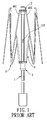
- a conventional umbrella is shown to include an elongate stem 1 and a runner 3 which is sleeved slidably on the stem 1 to connect pivotally with a stretch assembly 5 for supporting a rib assembly 4.
- a notch 2 includes a sleeve portion 201 which is sleeved on an upper end of the stem 1, and a mounting portion 202 for pivotally connecting a plurality of ribs 401 of the rib assembly 4.
- the runner 3 is movable between an upper position for stretching the rib assembly 4 and a lower position for collapsing the same.
- a spring-loaded stop 101 is disposed in the stem 1 so as to retain the runner 3 in the upper position.
- the ribs 401 cannot be brought into close proximity of the stem 1 due to the thickness of the sleeve portion 201 after being collapsed, as shown in Fig. 2, thereby resulting in inconvenient carrying and storage.
- the object of the present invention is to provide an umbrella in which ribs can be brought into close proximity of a stem after being collapsed so as to facilitate storage and carrying.
- the umbrella includes an elongate stem which has a tubular upper end portion, and.a lower end portion extending from the upper portion along an axis.
- the upper end portion has a top edge wall with inner and outer peripheries respectively surrounding the axis, an outer surrounding wall surface which extends downwardly from the outer periphery and which surrounds the axis, and an inner surrounding wall surface which extends downwardly from the inner periphery and which is disposed opposite to the outer surrounding wall surface.
- the upper end portion defines a plurality of slots which are angularly displaced from one another. Each of the slots extends radially and inwardly relative to the axis, extends from the top edge wall toward the lower end portion, and terminates at a slot edge wall.
- An anchored wire extends around the axis, and is disposed inwardly and radially of the inner surrounding wall surface.
- the wire has a plurality of anchored segments which are disposed to be respectively exposed from the slots such that each of the anchored segments is accessible radially.
- Each of the anchored segments is disposed proximate to the top edge wall along the axis.
- a canopy is mounted on the top edge wall.
- a cap member is disposed to fasten the canopy to the top edge wall.
- a rib assembly includes a plurality of ribs.
- Each rib has an anchoring end which is pivoted to a respective one of the anchored segments, a distal end which is disposed opposite to the anchoring end radial to the axis and which is disposed at an underside of the canopy to support the canopy in a spread-out position and in a collapsed position, and a bent portion which extends from the anchoring end toward the distal end.
- the bent portion is formed by bending a respective one of the ribs which is adjacent to the anchoring end towards the axis, thereby bringing the bent portion close to the slot edge wall.
- a tubular runner is slidably sleeved on the stem, and is movable between upper and lower positions respectively corresponding to the spread-out and collapsed positions of the canopy.
- a stretcher assembly is disposed to interconnect the rib assembly and the runner so as to stretch or retract the rib assembly, thereby placing the canopy in the spread-out position or the collapsed position when'the runner is moved to the upper position or the lower position,
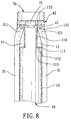
- an umbrella according to the present invention is shown to comprise an elongate tubular stem 10 which has an upper end portion 15 and a lower end portion 16 opposite to each other along an axis.
- the upper end portion 15 has a top edge wall 151 with inner and outer peripheries which respectively surround the axis, an outer surrounding wall surface 152 which extends downwardly from the outer periphery of the top edge wall 151 and which surrounds the axis, and an inner surrounding wall surface 153 which extends downwardly from the inner periphery of the top edge wall 151 and which is disposed opposite to the outer surrounding wall surface 152.
- the upper end portion 15 is of an integrally single-piece construction, and defines a plurality of slots 11 which are angularly displaced from one another.
- Each of the slots 11 extends radially and inwardly relative to the axis, extends from the top edge wall 151 toward the lower end portion 16, and terminates at a slot edge wall 111.
- An anchored wire 13 extends around the axis, and is disposed inwardly and radially of the inner surrounding wall surface 153 .
- the anchored wire 13 has a plurality of anchored segments 131 which are disposed to be respectively exposed from the slots 11 such that each of the anchored segments 131 is accessible radially.
- Each of the anchored segments 131 is disposed proximate to the top edge wall 151 along the axis.
- a support mount 40 has a lower major wall surface 43 which abuts against the top edge wall 151 of the upper end portion 15 of the stem 10, an upper major wall surface 44 which is formed with a threaded hole 42 that extends along the axis, and a plurality of elongate limiting portions 41 which extend downwardly from a periphery of the lower major wall surface 43 and which are displaced angularly from one another about the axis.
- the limiting portions 41 are disposed radially and outwardly of the outer surrounding wall surface 152 of the upper end portion 15 of the stem 10 and between two adjacent ones of the slots 11.
- a canopy 60 is mounted on the upper major wall surface 44.
- a cap member 70 has a threaded bolt 71 which extends along the axis and which engages threadedly the threaded hole 42 so as to clamp the canopy 60 between the cap member 70 and the support mount 40.
- a rib assembly 30 includes a plurality of ribs 31.
- Each rib 31 has an anchoring end 311 which is pivoted to a respective one of the anchored segments 131 of the anchored wire 13, a distal end which is disposed opposite to the anchoring end 311 radial to the axis and which is disposed at an underside of the canopy 60 to support the canopy 60 in a spread-out position and in a collapsed position, and a bent portion 312 which extends from the anchoring end 311 toward the distal end and which is formed by bending a respective one of the ribs 31 that is adjacent to the anchoring end 311, towards the axis.
- the bent portions 312 of the ribs 31 can be brought close to the slot edge walls 111 of the upper end portion 15 of the slots 11 in the stem 10.
- a tubular runner 20 is slidably sleeved on the stem 10, and is movable between upper and lower positions which respectively correspond to the spread-out and collapsed positions of the canopy 60.
- a stretcher assembly 50 is disposed to interconnect the rib assembly 30 and the runner 20 so as to stretch or retract the rib assembly 30, thereby placing the canopy 60 in the spread-out position or the collapsed position when the runner 20 is moved to the upper position or the lower position, respectively.
- a spring-loaded stop 14 is disposed in the stem 10 to retain the runner 20 in the upper position so as to spread the canopy 60.
- the anchoring ends 311 of the ribs 31 are pivoted to the anchored segments 131 which are disposed radially and inwardly of the inner surrounding wall surface 153 of the upper end portion 15 of the stem 10, and since the bent portions 312 are formed adjacent to the anchoring ends 311, the ribs 31 can be brought into close proximity of the stem 10 after the collapsing operation, thereby resulting in a compact size of the umbrella to facilitate storage and carrying.
- the upper end portion 15 of the stem 10 further has a plurality of lower slot walls 112 and a plurality of barrier walls 114.
- the lower slot walls 112 are formed integrally and respectively with the slot edge walls 111, and extend radially and inwardly therefrom relative to the axis to terminate at lower barrier edges 113, respectively.
- the barrier walls 114 are formed integrally and respectively with the lower barrier edges 113, and extend upwardly and respectively therefrom along the axis.
- Each of the barrier walls 114 is disposed inwardly and radially of a respective one of the anchored segments 131 of the anchored wire 13, and terminates at a top barrier edge 115 that is flush with and that is connected with the top edge wall 151.
Landscapes
- Walking Sticks, Umbrellas, And Fans (AREA)
Priority Applications (5)
| Application Number | Priority Date | Filing Date | Title |
|---|---|---|---|
| US10/214,075 US6722382B2 (en) | 2002-08-07 | 2002-08-07 | Umbrella |
| EP02256232A EP1396206B1 (fr) | 2002-08-07 | 2002-09-09 | Parapluie |
| AT02256232T ATE312530T1 (de) | 2002-09-09 | 2002-09-09 | Regenschirm |
| DE2002608025 DE60208025T2 (de) | 2002-09-09 | 2002-09-09 | Regenschirm |
| ES02256232T ES2252396T3 (es) | 2002-08-07 | 2002-09-09 | Paraguas. |
Applications Claiming Priority (2)
| Application Number | Priority Date | Filing Date | Title |
|---|---|---|---|
| US10/214,075 US6722382B2 (en) | 2002-08-07 | 2002-08-07 | Umbrella |
| EP02256232A EP1396206B1 (fr) | 2002-08-07 | 2002-09-09 | Parapluie |
Publications (2)
| Publication Number | Publication Date |
|---|---|
| EP1396206A1 true EP1396206A1 (fr) | 2004-03-10 |
| EP1396206B1 EP1396206B1 (fr) | 2005-12-14 |
Family
ID=32395459
Family Applications (1)
| Application Number | Title | Priority Date | Filing Date |
|---|---|---|---|
| EP02256232A Expired - Lifetime EP1396206B1 (fr) | 2002-08-07 | 2002-09-09 | Parapluie |
Country Status (3)
| Country | Link |
|---|---|
| US (1) | US6722382B2 (fr) |
| EP (1) | EP1396206B1 (fr) |
| ES (1) | ES2252396T3 (fr) |
Families Citing this family (17)
| Publication number | Priority date | Publication date | Assignee | Title |
|---|---|---|---|---|
| US6918399B2 (en) * | 2003-05-14 | 2005-07-19 | Chin Sung Ko | Automatic umbrella |
| US7210491B2 (en) * | 2003-11-12 | 2007-05-01 | Ping-Tung Su | Umbrella structure |
| US20050161068A1 (en) * | 2004-01-26 | 2005-07-28 | Ming-Gung Li | Umbrella frame |
| US20070051394A1 (en) * | 2005-09-06 | 2007-03-08 | Ming-Gung Li | Umbrella frame |
| US20070084489A1 (en) * | 2005-09-06 | 2007-04-19 | Ming-Gung Li | Umbrella frame |
| CN103371579B (zh) | 2012-04-19 | 2015-12-23 | 宁波万汇休闲用品有限公司 | 快速挂骨上下巢结构及相关伞具和快速挂骨方法 |
| US10060152B2 (en) | 2015-09-14 | 2018-08-28 | Oliver Joen-An Ma | Components for shade structures |
| US10631603B2 (en) | 2015-09-14 | 2020-04-28 | Oliver Joen-An Ma | Quick assembly methods and components for shade structures |
| DE202016008013U1 (de) | 2016-10-25 | 2017-03-07 | Qingdao Activa Shade Inc. | Schirmrippen Verbindungsanordnung |
| CN207561480U (zh) | 2016-12-07 | 2018-07-03 | 宁波万汇休闲用品有限公司 | 伞毂装配结构 |
| USD814173S1 (en) | 2016-12-21 | 2018-04-03 | ZHUN-AN Ma | Umbrella runner grip |
| USD826543S1 (en) | 2016-12-21 | 2018-08-28 | ZHUN-AN Ma | Umbrella housing |
| USD813525S1 (en) | 2016-12-21 | 2018-03-27 | ZHUN-AN Ma | Umbrella runner grip |
| USD828995S1 (en) | 2016-12-21 | 2018-09-25 | ZHUN-AN Ma | Umbrella housing |
| USD833137S1 (en) | 2017-09-27 | 2018-11-13 | ZHUN-AN Ma | Umbrella hub |
| US10653218B1 (en) | 2020-02-05 | 2020-05-19 | Dee Volin | Umbrella with projector lighting device |
| USD1119794S1 (en) | 2022-07-22 | 2026-03-24 | ZHUN-AN Ma | Combined umbrella crank housing and battery assembly |
Citations (4)
| Publication number | Priority date | Publication date | Assignee | Title |
|---|---|---|---|---|
| US5193566A (en) * | 1992-02-28 | 1993-03-16 | Ocean Import Export Inc. | Umbrella frame |
| US5253666A (en) * | 1992-09-10 | 1993-10-19 | Yung Shun Umbrella Co., Ltd. | Umbrella opening and closing device without use of spring latches |
| US5611233A (en) * | 1992-06-19 | 1997-03-18 | Crown Gear, B.V. | Transmission unit for driving two shafts lying essentially parallel |
| US5964235A (en) * | 1998-03-11 | 1999-10-12 | Wang; Max | Umbrella with an improved runner fastener |
Family Cites Families (2)
| Publication number | Priority date | Publication date | Assignee | Title |
|---|---|---|---|---|
| US449716A (en) * | 1891-04-07 | Thomas j | ||
| DE3346672C2 (de) * | 1983-12-23 | 1985-10-31 | Kortenbach & Rauh Kg, 5650 Solingen | Schirm |
-
2002
- 2002-08-07 US US10/214,075 patent/US6722382B2/en not_active Expired - Fee Related
- 2002-09-09 EP EP02256232A patent/EP1396206B1/fr not_active Expired - Lifetime
- 2002-09-09 ES ES02256232T patent/ES2252396T3/es not_active Expired - Lifetime
Patent Citations (4)
| Publication number | Priority date | Publication date | Assignee | Title |
|---|---|---|---|---|
| US5193566A (en) * | 1992-02-28 | 1993-03-16 | Ocean Import Export Inc. | Umbrella frame |
| US5611233A (en) * | 1992-06-19 | 1997-03-18 | Crown Gear, B.V. | Transmission unit for driving two shafts lying essentially parallel |
| US5253666A (en) * | 1992-09-10 | 1993-10-19 | Yung Shun Umbrella Co., Ltd. | Umbrella opening and closing device without use of spring latches |
| US5964235A (en) * | 1998-03-11 | 1999-10-12 | Wang; Max | Umbrella with an improved runner fastener |
Also Published As
| Publication number | Publication date |
|---|---|
| US6722382B2 (en) | 2004-04-20 |
| ES2252396T3 (es) | 2006-05-16 |
| EP1396206B1 (fr) | 2005-12-14 |
| US20040025915A1 (en) | 2004-02-12 |
Similar Documents
| Publication | Publication Date | Title |
|---|---|---|
| EP1396206B1 (fr) | Parapluie | |
| US5749386A (en) | Golf umbrella and support | |
| US6145523A (en) | Spread position securing device for beach parasols | |
| US7082953B2 (en) | Umbrella actuator | |
| KR102165164B1 (ko) | 우산 | |
| US20060151019A1 (en) | Electric spreading device for a parasol | |
| US7537016B1 (en) | Golf bag umbrella with a flexible joint threadedly secured to an intermediate portion of a telescopic center post | |
| GB2408450A (en) | Umbrella top notch or crown | |
| US8011379B2 (en) | Portable and compact umbrella | |
| US6948506B2 (en) | Umbrella with a rotatable canopy | |
| US6810893B1 (en) | Umbrella mechanism | |
| US6725870B1 (en) | Simple hanging parasol | |
| US7261112B2 (en) | Firm automatic multi-sectional collapsible umbrella structure | |
| CN202664507U (zh) | 伞套和伞装置 | |
| US20070062568A1 (en) | Umbrella with dome shape | |
| US20030221714A1 (en) | Umbrella | |
| US6910490B1 (en) | Umbrella apparatus | |
| KR101868080B1 (ko) | 지팡이를 구비한 우산 | |
| EP1486136B1 (fr) | Parapluie avec une structure couvrante rotative | |
| KR100508777B1 (ko) | 우산 | |
| KR100913419B1 (ko) | 휴대용 콤팩트 우산 | |
| EP1396205B1 (fr) | Parapluie | |
| US20050072452A1 (en) | Bumper for an umbrella | |
| KR20190127131A (ko) | 역방향으로 접히는 살없는 내장형 우산 | |
| US7401616B2 (en) | Umbrella with a foldable stem |
Legal Events
| Date | Code | Title | Description |
|---|---|---|---|
| PUAI | Public reference made under article 153(3) epc to a published international application that has entered the european phase |
Free format text: ORIGINAL CODE: 0009012 |
|
| 17P | Request for examination filed |
Effective date: 20020921 |
|
| AK | Designated contracting states |
Kind code of ref document: A1 Designated state(s): AT BE BG CH CY CZ DE DK EE ES FI FR GB GR IE IT LI LU MC NL PT SE SK TR |
|
| AX | Request for extension of the european patent |
Extension state: AL LT LV MK RO SI |
|
| AKX | Designation fees paid |
Designated state(s): AT BE BG CH CY CZ DE DK EE ES FI FR GB GR IE IT LI LU MC NL PT SE SK TR |
|
| GRAP | Despatch of communication of intention to grant a patent |
Free format text: ORIGINAL CODE: EPIDOSNIGR1 |
|
| GRAS | Grant fee paid |
Free format text: ORIGINAL CODE: EPIDOSNIGR3 |
|
| GRAA | (expected) grant |
Free format text: ORIGINAL CODE: 0009210 |
|
| AK | Designated contracting states |
Kind code of ref document: B1 Designated state(s): AT BE BG CH CY CZ DE DK EE ES FI FR GB GR IE IT LI LU MC NL PT SE SK TR |
|
| PG25 | Lapsed in a contracting state [announced via postgrant information from national office to epo] |
Ref country code: CZ Free format text: LAPSE BECAUSE OF FAILURE TO SUBMIT A TRANSLATION OF THE DESCRIPTION OR TO PAY THE FEE WITHIN THE PRESCRIBED TIME-LIMIT Effective date: 20051214 Ref country code: LI Free format text: LAPSE BECAUSE OF FAILURE TO SUBMIT A TRANSLATION OF THE DESCRIPTION OR TO PAY THE FEE WITHIN THE PRESCRIBED TIME-LIMIT Effective date: 20051214 Ref country code: SK Free format text: LAPSE BECAUSE OF FAILURE TO SUBMIT A TRANSLATION OF THE DESCRIPTION OR TO PAY THE FEE WITHIN THE PRESCRIBED TIME-LIMIT Effective date: 20051214 Ref country code: BE Free format text: LAPSE BECAUSE OF FAILURE TO SUBMIT A TRANSLATION OF THE DESCRIPTION OR TO PAY THE FEE WITHIN THE PRESCRIBED TIME-LIMIT Effective date: 20051214 Ref country code: FI Free format text: LAPSE BECAUSE OF FAILURE TO SUBMIT A TRANSLATION OF THE DESCRIPTION OR TO PAY THE FEE WITHIN THE PRESCRIBED TIME-LIMIT Effective date: 20051214 Ref country code: AT Free format text: LAPSE BECAUSE OF FAILURE TO SUBMIT A TRANSLATION OF THE DESCRIPTION OR TO PAY THE FEE WITHIN THE PRESCRIBED TIME-LIMIT Effective date: 20051214 Ref country code: NL Free format text: LAPSE BECAUSE OF FAILURE TO SUBMIT A TRANSLATION OF THE DESCRIPTION OR TO PAY THE FEE WITHIN THE PRESCRIBED TIME-LIMIT Effective date: 20051214 Ref country code: CH Free format text: LAPSE BECAUSE OF FAILURE TO SUBMIT A TRANSLATION OF THE DESCRIPTION OR TO PAY THE FEE WITHIN THE PRESCRIBED TIME-LIMIT Effective date: 20051214 |
|
| REG | Reference to a national code |
Ref country code: GB Ref legal event code: FG4D |
|
| REG | Reference to a national code |
Ref country code: CH Ref legal event code: EP |
|
| REG | Reference to a national code |
Ref country code: IE Ref legal event code: FG4D |
|
| REF | Corresponds to: |
Ref document number: 60208025 Country of ref document: DE Date of ref document: 20060119 Kind code of ref document: P |
|
| PG25 | Lapsed in a contracting state [announced via postgrant information from national office to epo] |
Ref country code: DK Free format text: LAPSE BECAUSE OF FAILURE TO SUBMIT A TRANSLATION OF THE DESCRIPTION OR TO PAY THE FEE WITHIN THE PRESCRIBED TIME-LIMIT Effective date: 20060314 Ref country code: SE Free format text: LAPSE BECAUSE OF FAILURE TO SUBMIT A TRANSLATION OF THE DESCRIPTION OR TO PAY THE FEE WITHIN THE PRESCRIBED TIME-LIMIT Effective date: 20060314 Ref country code: GR Free format text: LAPSE BECAUSE OF FAILURE TO SUBMIT A TRANSLATION OF THE DESCRIPTION OR TO PAY THE FEE WITHIN THE PRESCRIBED TIME-LIMIT Effective date: 20060314 Ref country code: BG Free format text: LAPSE BECAUSE OF FAILURE TO SUBMIT A TRANSLATION OF THE DESCRIPTION OR TO PAY THE FEE WITHIN THE PRESCRIBED TIME-LIMIT Effective date: 20060314 |
|
| PG25 | Lapsed in a contracting state [announced via postgrant information from national office to epo] |
Ref country code: PT Free format text: LAPSE BECAUSE OF FAILURE TO SUBMIT A TRANSLATION OF THE DESCRIPTION OR TO PAY THE FEE WITHIN THE PRESCRIBED TIME-LIMIT Effective date: 20060515 |
|
| REG | Reference to a national code |
Ref country code: ES Ref legal event code: FG2A Ref document number: 2252396 Country of ref document: ES Kind code of ref document: T3 |
|
| NLV1 | Nl: lapsed or annulled due to failure to fulfill the requirements of art. 29p and 29m of the patents act | ||
| REG | Reference to a national code |
Ref country code: CH Ref legal event code: PL |
|
| PGFP | Annual fee paid to national office [announced via postgrant information from national office to epo] |
Ref country code: ES Payment date: 20060703 Year of fee payment: 5 Ref country code: GB Payment date: 20060703 Year of fee payment: 5 |
|
| ET | Fr: translation filed | ||
| PG25 | Lapsed in a contracting state [announced via postgrant information from national office to epo] |
Ref country code: IE Free format text: LAPSE BECAUSE OF NON-PAYMENT OF DUE FEES Effective date: 20060911 |
|
| PG25 | Lapsed in a contracting state [announced via postgrant information from national office to epo] |
Ref country code: MC Free format text: LAPSE BECAUSE OF NON-PAYMENT OF DUE FEES Effective date: 20060930 |
|
| PGFP | Annual fee paid to national office [announced via postgrant information from national office to epo] |
Ref country code: IT Payment date: 20060930 Year of fee payment: 5 |
|
| PLBE | No opposition filed within time limit |
Free format text: ORIGINAL CODE: 0009261 |
|
| STAA | Information on the status of an ep patent application or granted ep patent |
Free format text: STATUS: NO OPPOSITION FILED WITHIN TIME LIMIT |
|
| PGFP | Annual fee paid to national office [announced via postgrant information from national office to epo] |
Ref country code: DE Payment date: 20061031 Year of fee payment: 5 |
|
| 26N | No opposition filed |
Effective date: 20060915 |
|
| REG | Reference to a national code |
Ref country code: FR Ref legal event code: ST Effective date: 20070531 |
|
| PG25 | Lapsed in a contracting state [announced via postgrant information from national office to epo] |
Ref country code: FR Free format text: LAPSE BECAUSE OF NON-PAYMENT OF DUE FEES Effective date: 20061002 |
|
| GBPC | Gb: european patent ceased through non-payment of renewal fee |
Effective date: 20070909 |
|
| PG25 | Lapsed in a contracting state [announced via postgrant information from national office to epo] |
Ref country code: EE Free format text: LAPSE BECAUSE OF FAILURE TO SUBMIT A TRANSLATION OF THE DESCRIPTION OR TO PAY THE FEE WITHIN THE PRESCRIBED TIME-LIMIT Effective date: 20051214 |
|
| PG25 | Lapsed in a contracting state [announced via postgrant information from national office to epo] |
Ref country code: LU Free format text: LAPSE BECAUSE OF NON-PAYMENT OF DUE FEES Effective date: 20060909 Ref country code: TR Free format text: LAPSE BECAUSE OF FAILURE TO SUBMIT A TRANSLATION OF THE DESCRIPTION OR TO PAY THE FEE WITHIN THE PRESCRIBED TIME-LIMIT Effective date: 20051214 Ref country code: DE Free format text: LAPSE BECAUSE OF NON-PAYMENT OF DUE FEES Effective date: 20080401 |
|
| PG25 | Lapsed in a contracting state [announced via postgrant information from national office to epo] |
Ref country code: CY Free format text: LAPSE BECAUSE OF FAILURE TO SUBMIT A TRANSLATION OF THE DESCRIPTION OR TO PAY THE FEE WITHIN THE PRESCRIBED TIME-LIMIT Effective date: 20051214 Ref country code: GB Free format text: LAPSE BECAUSE OF NON-PAYMENT OF DUE FEES Effective date: 20070909 |
|
| REG | Reference to a national code |
Ref country code: ES Ref legal event code: FD2A Effective date: 20070910 |
|
| PG25 | Lapsed in a contracting state [announced via postgrant information from national office to epo] |
Ref country code: ES Free format text: LAPSE BECAUSE OF NON-PAYMENT OF DUE FEES Effective date: 20070910 |
|
| PG25 | Lapsed in a contracting state [announced via postgrant information from national office to epo] |
Ref country code: IT Free format text: LAPSE BECAUSE OF NON-PAYMENT OF DUE FEES Effective date: 20070909 |