EP1396218A1 - Oreiller avec un remplissage gazeux - Google Patents
Oreiller avec un remplissage gazeux Download PDFInfo
- Publication number
- EP1396218A1 EP1396218A1 EP03020245A EP03020245A EP1396218A1 EP 1396218 A1 EP1396218 A1 EP 1396218A1 EP 03020245 A EP03020245 A EP 03020245A EP 03020245 A EP03020245 A EP 03020245A EP 1396218 A1 EP1396218 A1 EP 1396218A1
- Authority
- EP
- European Patent Office
- Prior art keywords
- chamber
- air
- filling
- pillow
- chambers
- Prior art date
- Legal status (The legal status is an assumption and is not a legal conclusion. Google has not performed a legal analysis and makes no representation as to the accuracy of the status listed.)
- Withdrawn
Links
- 230000002093 peripheral effect Effects 0.000 claims abstract description 34
- 239000004753 textile Substances 0.000 claims abstract description 19
- 239000011888 foil Substances 0.000 claims abstract description 16
- 238000004519 manufacturing process Methods 0.000 claims abstract description 5
- 239000002245 particle Substances 0.000 claims abstract description 4
- 239000000835 fiber Substances 0.000 claims abstract description 3
- 239000013013 elastic material Substances 0.000 claims abstract 2
- 238000003466 welding Methods 0.000 claims description 25
- 238000010438 heat treatment Methods 0.000 claims description 16
- 238000000034 method Methods 0.000 claims description 5
- 230000035699 permeability Effects 0.000 claims description 5
- 238000009423 ventilation Methods 0.000 claims description 5
- 239000000853 adhesive Substances 0.000 claims description 3
- 230000001070 adhesive effect Effects 0.000 claims description 3
- 230000008569 process Effects 0.000 claims description 2
- 238000004080 punching Methods 0.000 claims 1
- 230000005855 radiation Effects 0.000 claims 1
- 244000144992 flock Species 0.000 abstract 1
- 239000007789 gas Substances 0.000 description 22
- 239000000463 material Substances 0.000 description 8
- 239000006260 foam Substances 0.000 description 7
- 239000004033 plastic Substances 0.000 description 7
- 229920003023 plastic Polymers 0.000 description 7
- 230000037396 body weight Effects 0.000 description 5
- 239000003292 glue Substances 0.000 description 5
- 230000000694 effects Effects 0.000 description 4
- 239000007788 liquid Substances 0.000 description 4
- 239000004743 Polypropylene Substances 0.000 description 3
- 239000004744 fabric Substances 0.000 description 3
- 229920001155 polypropylene Polymers 0.000 description 3
- 230000006978 adaptation Effects 0.000 description 2
- 238000004026 adhesive bonding Methods 0.000 description 2
- 230000008901 benefit Effects 0.000 description 2
- 238000009826 distribution Methods 0.000 description 2
- 239000000945 filler Substances 0.000 description 2
- 239000002985 plastic film Substances 0.000 description 2
- 229920006255 plastic film Polymers 0.000 description 2
- 239000002984 plastic foam Substances 0.000 description 2
- -1 polypropylene Polymers 0.000 description 2
- 239000004814 polyurethane Substances 0.000 description 2
- 238000007789 sealing Methods 0.000 description 2
- 241000894006 Bacteria Species 0.000 description 1
- 206010011985 Decubitus ulcer Diseases 0.000 description 1
- 206010033799 Paralysis Diseases 0.000 description 1
- 206010037180 Psychiatric symptoms Diseases 0.000 description 1
- 239000003570 air Substances 0.000 description 1
- 238000007664 blowing Methods 0.000 description 1
- 210000000988 bone and bone Anatomy 0.000 description 1
- 238000004140 cleaning Methods 0.000 description 1
- 239000012459 cleaning agent Substances 0.000 description 1
- 239000002817 coal dust Substances 0.000 description 1
- 239000011248 coating agent Substances 0.000 description 1
- 238000000576 coating method Methods 0.000 description 1
- 230000006835 compression Effects 0.000 description 1
- 238000007906 compression Methods 0.000 description 1
- 238000005520 cutting process Methods 0.000 description 1
- 239000000645 desinfectant Substances 0.000 description 1
- 210000004177 elastic tissue Anatomy 0.000 description 1
- 238000005516 engineering process Methods 0.000 description 1
- 239000008187 granular material Substances 0.000 description 1
- 239000011261 inert gas Substances 0.000 description 1
- 244000005700 microbiome Species 0.000 description 1
- 230000005012 migration Effects 0.000 description 1
- 238000013508 migration Methods 0.000 description 1
- 230000000149 penetrating effect Effects 0.000 description 1
- 229920000642 polymer Polymers 0.000 description 1
- 238000009417 prefabrication Methods 0.000 description 1
- 230000009467 reduction Effects 0.000 description 1
- 230000000717 retained effect Effects 0.000 description 1
- 238000005096 rolling process Methods 0.000 description 1
- 238000007665 sagging Methods 0.000 description 1
- 230000003319 supportive effect Effects 0.000 description 1
- 238000005406 washing Methods 0.000 description 1
- XLYOFNOQVPJJNP-UHFFFAOYSA-N water Substances O XLYOFNOQVPJJNP-UHFFFAOYSA-N 0.000 description 1
Images



Classifications
-
- A—HUMAN NECESSITIES
- A47—FURNITURE; DOMESTIC ARTICLES OR APPLIANCES; COFFEE MILLS; SPICE MILLS; SUCTION CLEANERS IN GENERAL
- A47G—HOUSEHOLD OR TABLE EQUIPMENT
- A47G9/00—Bed-covers; Counterpanes; Travelling rugs; Sleeping rugs; Sleeping bags; Pillows
- A47G9/10—Pillows
- A47G9/1027—Details of inflatable pillows
-
- A—HUMAN NECESSITIES
- A47—FURNITURE; DOMESTIC ARTICLES OR APPLIANCES; COFFEE MILLS; SPICE MILLS; SUCTION CLEANERS IN GENERAL
- A47G—HOUSEHOLD OR TABLE EQUIPMENT
- A47G9/00—Bed-covers; Counterpanes; Travelling rugs; Sleeping rugs; Sleeping bags; Pillows
- A47G2009/003—Bed-covers; Counterpanes; Travelling rugs; Sleeping rugs; Sleeping bags; Pillows with inflatable members
Definitions
- the invention relates to a cushion filled with gas, in particular filled with air.
- Such pillows are well known. They are regularly inflatable pillows.
- the disadvantage of these pillows is the dosage of the air filling. If the filling is too large, the pillow feels hard. If the cushion is insufficiently filled, the cushion will lie through, ie you can feel the surface under the cushion. There is always a wobble on conventional inflatable cushions, which affects the lying comfort. With increasing pillow size, the name changes from pillow to mattress. In the following this distinction is not made and the term "pillow" also includes mattresses.
- Pillows are already known which are filled with air, gas, granules, liquid or other materials.
- Air-filled pillows are also known, the air filling of which is adjustable before use. Every known air mattress is adjustable. From DE 29719434 pillows are also known from which the air filling can escape partially under load until the pillow has placed itself on a body in the desired manner.
- pillows are known from GB-1035490 A with different chambers, the walls of which are permeable to air, so that air can escape from the loaded chambers into other chambers under load. When the cushions are relieved, the cushions are largely deformed again.
- DE 69611701 A2 a pillow with several chambers is described, with differently used chambers being used in parallel. In the example, chambers with liquid filling are used, which are connected to one another in such a way that the liquid flows from one chamber into other chambers under chamber load. The same applies to the air filling of the chambers provided for the rest.
- the invention is therefore based on the object of an air-filled or gas-filled cushion create that has a greater lying comfort.
- the invention is based on that from the GB 1035490 A known concept.
- the invention has recognized that compliance and Adaptation of the cushion areas to the user in the system is still not satisfactory Show results.
- the feeling of comfort is correspondingly low.
- the pillow has a main chamber, for example as a central chamber, which is provided with an air filling or a gas filling in the initial situation.
- the central chamber is surrounded by a peripheral chamber.
- the pillow wall between the two chambers is air-permeable or gas-permeable, so that when the pillow is used, the air or gas under body weight partially escapes from the central chamber into the peripheral chamber.
- the air or gas permeability is explained below.
- the pillow adapts to the surface by the escape of air or gas Body part very well.
- the body part slowly sinks.
- the air or gas flows from the central chamber into the peripheral chamber repressed. With each movement, a new adjustment takes place. That gives a high Comfort feeling.
- the slow escape of the air filling from the central chamber into the peripheral chamber, as well as the backflow of air results in an additional feeling of comfort when the cushion is partially relieved or when the user changes position.
- the dimensions of the chambers can be different or the same.
- the connection of the chambers causes the self-regulating air distribution / migration of air.
- a central or central chamber is preferably provided in the cushion, which is surrounded by an annular chamber.
- the central chamber is the main chamber in this example. Both chambers experience a special volume behavior in the initial position before use. Without stress, an elastic filling, preferably in the main chamber, ensures that the main chamber is maximally expanded. In the closed system of both chambers, the main chamber only fills with air from the other chamber.
- this is the annular chamber, the peripheral chamber.
- the annular, peripheral chamber is partially or largely emptied. With a smaller volume of the annular, peripheral chamber, this chamber is practically completely emptied in the starting position.
- the main chamber experiences a load which causes the main chamber to compress and escape from the main chamber into the annular peripheral chamber. For example, a volume ratio of 50:60 between the two chambers can result.
- the system according to the invention can also be used on neck pillows, which Surround the user's neck in a horseshoe shape.
- the peripheral Contribute chamber to support the main chamber as described above.
- a setting of the air content is optionally found in the system according to the invention the user's body weight instead. This can make an attitude towards men, women and children are done.
- the pillows of the invention are according to the Body weight hard with high body weight or soft with low body weight.
- the system according to the invention can advantageously be used without adjustment Air exchange with the surrounding atmosphere.
- the air or gas permeability is optionally achieved by perforating the Chamber wall and / or by an air or gas permeable textile Chamber wall and / or due to incomplete connection of foils from which the air or gas-permeable chamber wall is formed.
- the desired one can be perforated Adjust air or gas permeability exactly.
- the use of an air or gas-permeable textile is preferably of a certain desired size for the Exit flow from the central chamber.
- the air or gas filling is preferably atmospheric in the unloaded state Print. Deviating from this, a slight overpressure can also be selected.
- the pressure must in any case be relatively close to the atmospheric pressure, because that Pillow otherwise does not experience significant deformation during use and the feeling of comfort does not occur.
- the right pressure can be achieved with just a few tries based on the feeling of comfort be determined.
- the volume of the central chamber and the peripheral chamber is thus one on top of the other agreed that the user is not sagging. That too can be done with a few tries Reduction or enlargement of the peripheral chamber can be determined.
- the cushion according to the invention also includes an airtight and waterproof cushion cover.
- the cushion cover is preferably also elastic and stretchable. Suitable for such covers for example a plastic film.
- a film made of polyurethane (PU) Application are e.g. with a thickness of 0.2 mm and a width of 150 cm available in any color.
- plastics are also suitable for the film.
- from multilayer films can be advantageous.
- the individual layers can be different Take over functions, e.g. can a film with a high sealing effect on the outside with a soft film layer, e.g. a foam layer can be combined.
- the film is at least up to 50 degrees Celsius, preferably up to 100 degrees Celsius temperature resistant.
- Plastic films are also sensitive to cleaning agents and Disinfectant insensitive. There is also a mechanically very resistant one Plastics such as polypropylene used for high pressure cleaning and for others Washing processes are suitable and can be brushed.
- the pillow according to the invention has hygienic advantages. There is no air or Moisture exchange with the environment takes place. This will cause bacteria and other Microorganisms prevented from settling in the pillow.
- the central chamber preferably consists of two film sections which lie one on top of the other and are glued or welded together at the edge.
- the welding or gluing can with filling included.
- the filling is preferably carried out only after Prefabrication of the central chamber through an open filling opening, which after the Filling is closed.
- the film sections can be perforated at the edge.
- For perforating is suitable for Example a needle roller.
- the perforation alone can provide the desired air passage cause so that the film sections are welded or glued all around the edge can.
- the film sections can also only be provided with windows at the edge that pass through a welded or glued textile are closed.
- All air passages or gas passages are designed in the opening width that the Filling a chamber is not carried out with the escaping gas. Is optional also the particle size of the filling chosen so large that the particles at the smaller opening be stopped for the escaping gas.
- the peripheral chamber is optionally attached to the edge of the central chamber by two circumferential film tabs with their inner edge on the upper and lower film for the central chamber can be welded or glued on. Alternatively, this can be done after the central chamber has been completed. It is both possible to have one To weld or glue the film tabs to the central chamber and then to weld or glue the foil tabs together at the edge, as well Conversely, first glue the foil tabs together at the edge and then on to weld or glue the central chamber.
- foil tab cutting instead of two foil tabs for the peripheral chamber, a single one can also be used Use foil tab cutting. This blank is then cut with the inner edge welded or glued to the finished central chamber. The outer edge is after that while leaving a sufficient margin for the peripheral chamber around the knocked around the outer edge of the central chamber and welded in place or glued to which otherwise the welding of the inner edge of the second film tab he follows.
- the covering foil sections are first welded together to effect the central chamber and then the overlapping foil sections at the edge to weld together.
- the overlapping film sections form with the Two-ply not just an additional sealing effect. They also contribute to the feeling of comfort at, because in the overlapping film sections a disturbing material impact between the Foils of the central chamber and the peripheral chamber is avoided.
- the pillows of the invention are also manufactured so that initially Uniform parts emerge, both as a pillow top and as a pillow bottom Use the central or after the whole or part of it Form chamber and the peripheral chamber.
- the plastic foils are welded together by heating the welding surfaces.
- the necessary heat can be used as contact heat or as radiant heat or by means of Hot gas or hot air or using high-frequency welding technology.
- heating stamps and heating blades and heating shoes or heating wedges and heating rollers are suitable, which are either placed on the welding surfaces or guided on the welding surfaces in a sliding or rolling manner. After the welding surfaces have warmed up to plasticization, the welding surfaces are pressed together.
- the film sections, film tabs and film cuts on the welding surfaces are heated simultaneously and uniformly by means of a heating stamp and are pressed against one another immediately after removal of the heating stamp.
- a heating shoe or heating wedge is advantageous for smaller quantities.
- the film sections, film tabs and film cuts can lie one above the other and the heating shoe or heating wedge moves between the welding surfaces along the intended weld seam.
- pressure tools preferably rollers, are provided, which generate the welding pressure necessary for the welding.
- the welding surfaces are prepared in such a way that they react to the vibrations. This is preferably done by coating with a reactive material.
- the material can be applied firmly. But it can also be a Liquid, e.g. Water, or a powdery material, e.g. Coal dust, act.
- the film sections, film tabs and film cuts are glued or welded to one another lying flat and the chamber is filled with restoring means and air or gas through a filling opening after completion.
- the filling opening is then closed, preferably by gluing or welding.
- air as the means of transport, for example, and to provide a ventilation opening in addition to the filling opening.
- the ventilation opening can be limited to the peripheral chamber.
- the fibers, flakes and other restoring means mentioned above can be carried into the central chamber with appropriate air pressure. The excess air then escapes through the air-permeable chamber wall into the peripheral chamber and there through the ventilation opening.
- the return means is retained by the air-permeable chamber wall.
- the filler opening can be formed by a thin plastic tube which, in the case of film sections, film tabs and film cuts lying flat on top of one another, has one end in the weld seam / adhesive seam of the central chamber and the other end in the weld seam / adhesive seam of the peripheral chamber. Then a blowing device with a corresponding mouthpiece can penetrate the hose and blow in the filling.
- a ventilation opening can be omitted if the central chamber is filled first is completed and film sections, film tabs and film cuts for the peripheral Chamber are then attached.
- Gases with particularly long-chain molecules are also suitable, which have a particularly high resistance when penetrating through the plastic opposes.
- the pillow according to the invention can be combined with any pillowcases and the pillow can have a round shape or a different shape, especially body have adapted shapes.
- the cushion also includes an upper film tab 4 and a lower film tab 8. Both film tabs form a rectangular ring. At the inner edge, the two film tabs 4 and 8 are welded to the film sections 1 and 2 of the central chamber 7. The weld seam is designated 10. In addition, the two film tabs 4 and 8 are welded together at the outer edge. The weld seam is designated 12. As a result, the two film tabs 4 and 8 form a peripheral chamber 6 at the edge of the central chamber 7. The wall between the chambers 6 and 7 is permeable, so that air can escape from the central chamber 7 into the peripheral chamber 6 and flow back again. Furthermore, there is a filling with shredded plastic foam in the central chamber 7. In the exemplary embodiment, it is polyurethane (PU) foam. All foils are made of polypropylene (PP). The plastic foam gives the central chamber 7 a resilience with a force of 1 kg per square meter.
- PU polyurethane
- FIG. 3 The use of the pillow according to the invention is shown in Fig. 3.
- An overlying body part brings about a compression of the central chamber 7.
- the central chamber 7 adapts to the shape of the body part in the exemplary embodiment within a few minutes, here 5 minutes, with the escape of air into the peripheral chamber 6.
- the restoring force causes an independent reshaping of the pillow in the initial shape.
- the air flows from the peripheral chamber 6 into the central chamber 7 back.
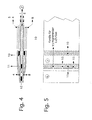
- Fig. 4 shows a procedure in pillow manufacturing. First, the film sections 1 and 2 are placed on top of one another and welded together. Subsequently, the film sections 1 and 2 are enclosed between the film sections 4 and 8 lying flat and the film sections 4 and 8 are welded together to produce the weld seam 12.
- Fig. 5 shows in plan view that the weld 11 consists of sections.
- the Sections are created by interrupting the welding process. Between the sections there are channels 15.
- the channels 15 give the wall between the chambers 6 and 7 permeability described. In the exemplary embodiment, a large number of channels are small Diameter provided. In other embodiments, fewer channels are included provided larger diameter.
- the opening width of the channels determines the Duration of air outflow into the peripheral chamber.
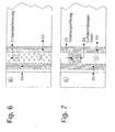
- the embodiment according to FIG. 6 differs from the embodiment according to FIGS. 4 and 5 by a continuous weld seam 20 instead of the weld seam 11. Furthermore, instead of the channels 15, an edge perforation 21 of the film sections 1 and 2 is provided between the weld seams 20 and 10. The perforation is achieved with needles. The needle diameter is preferably selected so that permanent openings are created. In other embodiments, the openings are punched.
- the embodiment according to FIG. 7 differs from the embodiments 5 and 6 that instead of the channels 15 and instead of the perforation 21 in windows or openings 25 between the weld seams 10 and 20 at regular intervals are provided in the film sections 1 and 2 and that the openings 25 with a air-permeable textile 26 are covered.
- the textile 26 is associated with the Foil section welded.
- the textile 26 is a fabric and consists of the same Plastic like the foils.
- FIG. 8 shows, instead of the film sections 1 and 2, other film sections 30 and 31 with textile edge strips 32 and 33.
- the edge strips 32 and 33 consist of a fabric.
- a finer fabric is provided in order to generate the same total resistance when flowing through with air as in the other exemplary embodiments.
- the weld seams between the film sections 30 and 31 and the edge strips 32 and 33 are denoted by 37.
- further film sections 34 and 35 are shown in FIG. 8, which surround the central chamber in a closed manner.
- the film sections 40 are enclosed by further film sections 43.
- the weld seams between the edges of the film sections 40 are designated 41, the weld seams between the film sections 43 are designated 42.
- the film sections 43 cover the central chamber like the film sections 34 and 35.
- Welding seams 39 are nevertheless provided at the points at which the welding seams 10 are located in the other exemplary embodiments.
- a fill opening 44 is also shown.
- the filling opening 44 is formed by a tube made of the same material as the foils.
- the hose extends through the weld seams 41 and 42.
- the foam chips provided as filling for the central chamber are blown through the filling opening 44.
- the dimensions of the foam chips are adapted to the filling opening.
- the soft nature of the foam chips makes filling easier.
- the soft nature of the foam chips is the result of a low density of 20 kg per cubic meter in the exemplary embodiment, based on an unshaved foam block.
- FIG. 9 also shows schematically the pillow side which lies opposite the filling opening 44.
- the weld seam between the edges of the film sections 43 is designated 51 and a vent 50 is provided.
- This opening is also through a hose educated.
- the vent 50 allows the injected transport air to escape while the filled schnitzel on the air-permeable wall between the central chamber and in the peripheral chamber.
- the pillows shown have a rectangular shape and a narrow side of 500mm and one Long side or broad side of 650 mm.
- the peripheral chamber has one Cross-sectional width of 56 mm and a thickness of 260 mm when the pillow is loaded.
Landscapes
- Health & Medical Sciences (AREA)
- General Health & Medical Sciences (AREA)
- Otolaryngology (AREA)
- Pulmonology (AREA)
- Bedding Items (AREA)
Applications Claiming Priority (2)
| Application Number | Priority Date | Filing Date | Title |
|---|---|---|---|
| DE10241631 | 2002-09-08 | ||
| DE2002141631 DE10241631A1 (de) | 2002-09-08 | 2002-09-08 | Kissen mit Gasfüllung |
Publications (1)
| Publication Number | Publication Date |
|---|---|
| EP1396218A1 true EP1396218A1 (fr) | 2004-03-10 |
Family
ID=31502489
Family Applications (1)
| Application Number | Title | Priority Date | Filing Date |
|---|---|---|---|
| EP03020245A Withdrawn EP1396218A1 (fr) | 2002-09-08 | 2003-09-06 | Oreiller avec un remplissage gazeux |
Country Status (2)
| Country | Link |
|---|---|
| EP (1) | EP1396218A1 (fr) |
| DE (1) | DE10241631A1 (fr) |
Cited By (2)
| Publication number | Priority date | Publication date | Assignee | Title |
|---|---|---|---|---|
| CN103431695A (zh) * | 2013-07-16 | 2013-12-11 | 江苏爱伦家纺有限公司 | 立体舒颈气囊枕 |
| CN107296444A (zh) * | 2017-08-23 | 2017-10-27 | 海门市月彩纺织科技有限公司 | 一种新型多功能充气抱枕 |
Families Citing this family (1)
| Publication number | Priority date | Publication date | Assignee | Title |
|---|---|---|---|---|
| DE102011084870A1 (de) * | 2011-10-20 | 2013-04-25 | Sanders Gmbh | Kissen, Verwendung und Herstellung desselben |
Citations (5)
| Publication number | Priority date | Publication date | Assignee | Title |
|---|---|---|---|---|
| WO1992010966A1 (fr) * | 1990-12-19 | 1992-07-09 | Mackworth Medical Products Limited | Repose-tete |
| EP0976349A2 (fr) * | 1998-07-30 | 2000-02-02 | Sandra Seidl | Surface profilée gonflable de siège ou de lit comprenant support et/ou enveloppe |
| US6131219A (en) * | 1999-03-03 | 2000-10-17 | Roberts; Janet H. | Inflatable pillow |
| US6401279B1 (en) * | 2000-03-10 | 2002-06-11 | Jesse F. Vaughn | Neck supporting pillow |
| US20020092097A1 (en) * | 2001-01-12 | 2002-07-18 | Lee Marion O. | Orthotic pillow |
Family Cites Families (4)
| Publication number | Priority date | Publication date | Assignee | Title |
|---|---|---|---|---|
| GB1035490A (en) * | 1962-12-04 | 1966-07-06 | Ernest William Sidebottom | Thermal insulation material |
| US5638565A (en) * | 1995-04-07 | 1997-06-17 | Dielectrics Industries | Inflatable cushion |
| DE29618055U1 (de) * | 1996-10-18 | 1997-03-20 | METAMORPH GmbH modellierbare Kissen-Technik, 60489 Frankfurt | Abform und Lagerungsvorrichtung |
| DE29620216U1 (de) * | 1996-11-20 | 1997-02-20 | Wegener Gmbh, 52074 Aachen | Vorrichtung zum Verschweißen von Folienrändern |
-
2002
- 2002-09-08 DE DE2002141631 patent/DE10241631A1/de not_active Ceased
-
2003
- 2003-09-06 EP EP03020245A patent/EP1396218A1/fr not_active Withdrawn
Patent Citations (5)
| Publication number | Priority date | Publication date | Assignee | Title |
|---|---|---|---|---|
| WO1992010966A1 (fr) * | 1990-12-19 | 1992-07-09 | Mackworth Medical Products Limited | Repose-tete |
| EP0976349A2 (fr) * | 1998-07-30 | 2000-02-02 | Sandra Seidl | Surface profilée gonflable de siège ou de lit comprenant support et/ou enveloppe |
| US6131219A (en) * | 1999-03-03 | 2000-10-17 | Roberts; Janet H. | Inflatable pillow |
| US6401279B1 (en) * | 2000-03-10 | 2002-06-11 | Jesse F. Vaughn | Neck supporting pillow |
| US20020092097A1 (en) * | 2001-01-12 | 2002-07-18 | Lee Marion O. | Orthotic pillow |
Cited By (2)
| Publication number | Priority date | Publication date | Assignee | Title |
|---|---|---|---|---|
| CN103431695A (zh) * | 2013-07-16 | 2013-12-11 | 江苏爱伦家纺有限公司 | 立体舒颈气囊枕 |
| CN107296444A (zh) * | 2017-08-23 | 2017-10-27 | 海门市月彩纺织科技有限公司 | 一种新型多功能充气抱枕 |
Also Published As
| Publication number | Publication date |
|---|---|
| DE10241631A1 (de) | 2004-04-15 |
Similar Documents
| Publication | Publication Date | Title |
|---|---|---|
| DE69631672T2 (de) | Mit einem oberflächenmaterial versehener, mehrschichtiger sitz mit unterschiedlicher härte, und sein herstellungsverfahren | |
| DE2535058C2 (de) | Wegwerfwindel | |
| DE3337009C2 (fr) | ||
| DE69929599T2 (de) | Verfahren und vorrichtung zur herstellung von selbstaufblasbaren matratzen und kissen | |
| DE2758538C2 (fr) | ||
| EP2826663B1 (fr) | Dispositif de climatisation pour un siège de véhicule | |
| DE69327872T2 (de) | Luftlagerungssysteme | |
| DE19857386C2 (de) | Verfahren zur Herstellung eines luftbeaufschlagbaren Kissens | |
| DE2712580A1 (de) | Verfahren zur herstellung eines sitzes | |
| EP0945090A2 (fr) | Matelas | |
| DE1629485B2 (de) | Verfahren zum herstellen eines mit einem polsterueberzug versehenen kissens mit schaumstoffkern | |
| DE102004059806A1 (de) | Unterlage für den menschlichen Körper und Verfahren zur Herstellung derselben | |
| DE1879067U (de) | Einlegesohle. | |
| EP1554158A1 (fr) | Coussin pneumatique d'assise et de dossier adaptatif destine a des vehicules et des avions | |
| DE202005003539U1 (de) | Papiersack | |
| DE2641209A1 (de) | Verfahren zur herstellung von sitzteilen fuer fahrzeugsitze | |
| DE2018781A1 (de) | Verfahren zur Herstellung gasgefüllter Hohlkörper^ | |
| DE3330760A1 (de) | Polster mit luftdurchlaessigem bezug und schaumstoffkern | |
| DE3623728A1 (de) | Sitzelement und verfahren zur herstellung desselben | |
| DE1486677A1 (de) | Huelle aus Schaumstoff und Vorrichtung zu ihrer Herstellung | |
| DE2442528B2 (de) | Matratze aus geschäumtem Kunststoff | |
| EP1396218A1 (fr) | Oreiller avec un remplissage gazeux | |
| DE60113748T2 (de) | Reitsattel | |
| DE2362521A1 (de) | Polsterung und verfahren zu deren herstellung | |
| EP1205131B1 (fr) | Elément en mousse avec des creux |
Legal Events
| Date | Code | Title | Description |
|---|---|---|---|
| PUAI | Public reference made under article 153(3) epc to a published international application that has entered the european phase |
Free format text: ORIGINAL CODE: 0009012 |
|
| AK | Designated contracting states |
Kind code of ref document: A1 Designated state(s): AT BE BG CH CY CZ DE DK EE ES FI FR GB GR HU IE IT LI LU MC NL PT RO SE SI SK TR |
|
| AX | Request for extension of the european patent |
Extension state: AL LT LV MK |
|
| AKX | Designation fees paid |
Designated state(s): AT BE BG CH CY CZ DE DK EE ES FI FR GB GR HU IE IT LI LU MC NL PT RO SE SI SK TR |
|
| STAA | Information on the status of an ep patent application or granted ep patent |
Free format text: STATUS: THE APPLICATION IS DEEMED TO BE WITHDRAWN |
|
| 18D | Application deemed to be withdrawn |
Effective date: 20040911 |