EP1396222A2 - Sauggerät, insbesondere Vorsatz oder Teil eines Elektro-Staubsaugers - Google Patents
Sauggerät, insbesondere Vorsatz oder Teil eines Elektro-Staubsaugers Download PDFInfo
- Publication number
- EP1396222A2 EP1396222A2 EP03020058A EP03020058A EP1396222A2 EP 1396222 A2 EP1396222 A2 EP 1396222A2 EP 03020058 A EP03020058 A EP 03020058A EP 03020058 A EP03020058 A EP 03020058A EP 1396222 A2 EP1396222 A2 EP 1396222A2
- Authority
- EP
- European Patent Office
- Prior art keywords
- suction device
- bristle
- bristle roller
- actuator
- particular according
- Prior art date
- Legal status (The legal status is an assumption and is not a legal conclusion. Google has not performed a legal analysis and makes no representation as to the accuracy of the status listed.)
- Granted
Links
- 230000009471 action Effects 0.000 claims description 18
- 230000000694 effects Effects 0.000 abstract description 6
- 230000001419 dependent effect Effects 0.000 abstract description 2
- 239000000428 dust Substances 0.000 description 13
- 238000010521 absorption reaction Methods 0.000 description 9
- 230000008859 change Effects 0.000 description 7
- 239000000463 material Substances 0.000 description 3
- 238000000034 method Methods 0.000 description 3
- 230000008901 benefit Effects 0.000 description 2
- 230000005540 biological transmission Effects 0.000 description 2
- 238000006073 displacement reaction Methods 0.000 description 2
- 238000005259 measurement Methods 0.000 description 2
- 230000036316 preload Effects 0.000 description 2
- 230000008569 process Effects 0.000 description 2
- 230000035945 sensitivity Effects 0.000 description 2
- 238000010792 warming Methods 0.000 description 2
- 230000001680 brushing effect Effects 0.000 description 1
- 238000004140 cleaning Methods 0.000 description 1
- 230000006835 compression Effects 0.000 description 1
- 238000007906 compression Methods 0.000 description 1
- 230000001010 compromised effect Effects 0.000 description 1
- 230000003247 decreasing effect Effects 0.000 description 1
- 238000001514 detection method Methods 0.000 description 1
- 238000011156 evaluation Methods 0.000 description 1
- 238000009408 flooring Methods 0.000 description 1
- 230000006872 improvement Effects 0.000 description 1
- 239000002689 soil Substances 0.000 description 1
Images


Classifications
-
- A—HUMAN NECESSITIES
- A47—FURNITURE; DOMESTIC ARTICLES OR APPLIANCES; COFFEE MILLS; SPICE MILLS; SUCTION CLEANERS IN GENERAL
- A47L—DOMESTIC WASHING OR CLEANING; SUCTION CLEANERS IN GENERAL
- A47L9/00—Details or accessories of suction cleaners, e.g. mechanical means for controlling the suction or for effecting pulsating action; Storing devices specially adapted to suction cleaners or parts thereof; Carrying-vehicles specially adapted for suction cleaners
- A47L9/02—Nozzles
- A47L9/04—Nozzles with driven brushes or agitators
- A47L9/0405—Driving means for the brushes or agitators
- A47L9/0411—Driving means for the brushes or agitators driven by electric motor
-
- A—HUMAN NECESSITIES
- A47—FURNITURE; DOMESTIC ARTICLES OR APPLIANCES; COFFEE MILLS; SPICE MILLS; SUCTION CLEANERS IN GENERAL
- A47L—DOMESTIC WASHING OR CLEANING; SUCTION CLEANERS IN GENERAL
- A47L9/00—Details or accessories of suction cleaners, e.g. mechanical means for controlling the suction or for effecting pulsating action; Storing devices specially adapted to suction cleaners or parts thereof; Carrying-vehicles specially adapted for suction cleaners
- A47L9/02—Nozzles
- A47L9/04—Nozzles with driven brushes or agitators
- A47L9/0427—Gearing or transmission means therefor
- A47L9/0444—Gearing or transmission means therefor for conveying motion by endless flexible members, e.g. belts
Definitions
- the invention first relates to a suction device, in particular attachment or part an electric vacuum cleaner, preferably a suction brush device with a suction channel for the care of carpets, with a suction channel and an electric motor and one or more bristle rollers driven thereby, wherein the bristle rollers in the vertical direction for different effects are movably supported on the carpet.
- an electric vacuum cleaner preferably a suction brush device with a suction channel for the care of carpets, with a suction channel and an electric motor and one or more bristle rollers driven thereby, wherein the bristle rollers in the vertical direction for different effects are movably supported on the carpet.
- Suction devices in particular suction brush devices of the type in question known and serve in particular the suction brush cleaning of carpets
- the suction is supported by electric motor driven, rotating bristle rollers, the bristle tufts by mechanical action loosen the dust / dirt in the carpet.
- the interpretation of the action force Such bristle rollers are compromised because on the one hand a high dust absorption and on the other hand a gentle action on the Carpet is desired.
- Benefit from high dust absorption as stiff as possible bristles or tufts of bristles and a high bristle board over the underbody and high speeds. In this way high mechanical force can be brought from the bristles into the carpet become.
- such an interpretation has a negative effect on the carpet damage.
- the parameter for keeping the force introduced constant the vacuum detected in the suction channel or in the suction mouth area used.
- the Measurement signals of a pressure sensor actively set the action of the bristle roller become.
- the negative pressure is direct for active control, for example of a pneumatically acting on the bristle roller Adjustment element is used.
- the invention further relates to a suction device according to the features of Preamble of claim 1.
- the action can be influenced by changing the speed of the bristle roller.
- the speed of the electric motor driving the bristle rollers is corresponding controlled, so preferably by changing the speed by means of a electronic speed control of the electric motor.
- a leading edge control, a plus-width modylation or others appropriate procedures are used.
- the action by changing the board position of the bristle roller in vertical Direction.
- the bristle roller can do this be stored in a vertical slot.
- a solution is preferred in which the bristle roller is attached to a rocker. proposed In this regard, the management board position of the bristle roller will change a spring action on the bristle roller acting in the vertical direction can be influenced. For example, via an actuator or the like adjusted the spring preload acting on the bristle roller the measured rotational resistance and / or negative pressure can be varied.
- the adjustment path describes the bristle roller axis a circular line section, but the radius is chosen so large that a change in the bristle board position in the The sense of the invention is achieved in the vertical direction.
- the adjustment of the bristle roller in the vertical direction can be done by an actuator which, for example. in the form of an electromechanically operating actuating stamp is.
- This actuator can thus be an electrically extendable element. Is conceivable also a pneumatically extendable element or a bimetal element. Further In this regard, a piezo actuator or electrochemical actuator is also conceivable. It is further proposed that without the influence of the influence of Bristle roller in the carpet actively adjustable element the bristle roller is lifted off the carpet rather than pressed on it.
- the vertical control of the bristle roller can also be used to For example, the bristle rollers in the hard floor area manually by the user or by automatic floor covering detection from the suction mouth area with which coarser suction goods pass this area can.
- Another significant advantage of the present invention is that that the force brought into the carpet is independent of the particular one Degree of wear of the bristles is, which means over the entire permissible operating time the bristle rollers always care for carpets differently Type is guaranteed.
- Through the configuration according to the invention is an improvement in the dust absorption of robust carpets achieved without increasing carpet wear on sensitive carpets.
- a system is created that applies the contact pressure of the bristles the carpet and thus the height relative to the chassis of the suction device is active, i.e. without manual influence by the user.
- FIG. 1 A motor-driven one is shown and described with reference to FIG Suction device 1 in the form of a suction brush device, which is shown in the Embodiment is designed as an attachment for a vacuum cleaner.
- the brush device 1 essentially consists of a housing 2 and a Pipe connection piece 3 together.
- a suction channel extends in the housing 2 4 starting from the pipe connection piece 3 into a suction space 5.
- the latter is located in a front area, which is the pipe connection piece 3 faces away and extends almost over the entire width of the housing.
- the toothed belt drive or the belt housing 9 extends approximately from the Center of the suction chamber 5 starting perpendicular to the drive shaft 8 up to the axis x.
- the toothed belt 7 engages at the end assigned to the drive shaft 8, at least within a receiving part 10, on a drive pulley 11, of the two-sided drive shaft 8 goes out. The latter extends so each starting from the drive pulley 11 into a lateral end region the suction chamber 5.
- the device base 13 partially broken open in FIG. 1 becomes on the suction space 5 opposite side, d. H. at the level of the pipe connection 3, from two rollers 14 arranged on both sides of the pipe connecting piece 3 pass through.
- the brush device 1 is for use as a conventional attachment for an electric vacuum cleaner for caring for carpets, especially for vacuuming the like, equipped with bristle rollers 16.
- These bristle rollers 16 are in 1 shown in broken lines.
- Each bristle roller 16 is a hollow body formed and is on the outside with two rows of bristles offset by 180 ° 18, which extend from an end region of the bristle roller 16 extend spirally around 180 ° starting from the latter.
- the bristle rollers 16 are pushed onto the drive shafts 8 and extend in the installed state starting from the receiving part 10 to in the end area of the suction chamber 5.
- the drive shafts 8 carrying belt housing 9 mounted like a seesaw about the axis x of the electric motor 6.
- the alignment is selected here so that the bristles of the rows of bristles 18 are separated by a the bottom 13 provided suction chamber opening 19 of the suction chamber 18 down protrude above the bottom 13, whereby the bristles when the bristle rollers rotate 16 engage mechanically in the carpet 20 to be cleaned.
- a schematically indicated measuring device 21 is provided, with which the rotational resistance of the bristle rollers 16 is determined, this by evaluating the motor current that is in turn dependent is of the type of carpet to be cared for 20.
- About control algorithms is introduced into the carpet 20 via the bristle rollers 16 Force kept at a constant value. This can be done, for example, by changing the speed of the electric motor 6, this speed change is preferably achieved by a phase control.
- the bristle board b adjustable to keep the force applied constant.
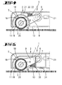
- FIG. 3 An alternative solution is shown in FIG. 3. This solution is about the measuring device 21 controls a servomotor, not shown, by means of which an eccentric disc acting on the rocker-like belt housing 9 24 is rotatable. This also means that the bristle board b is through Change of the bristle roller axis y variable in the vertical direction (arrow a) adjustable.
- Another option is to combine speed adjustment and change in the board position of the bristle rollers 16 depending from the determined values within the measuring device 21.
- a force-generating air spring 30 in the form of a pneumatic bellows provided that depending on the prevailing in the suction chamber 5 Negative pressure affects the vertical position of the bristle roller 16.
- An increased Vacuum is detected when the carpet is partially in the suction mouth the suction chamber 5 is sucked in and the brushes deeper into the carpet pile intervene when a gentle carpet treatment allows.
- Corresponding the air spring adjusting element 30 is used to adjust the lifting Bristle roller 16. In the event of insufficient vacuum in the suction chamber 5 the engagement of the bristles is increased by lowering the bristle roller 16.
- So 4 is the pneumatic unit (air spring 30) according to the embodiment in FIG. arranged in the ambient pressure range, the interior of the air spring 30 connected via a line 31 to the suction chamber 5, which is subject to negative pressure is.
- the air spring 30 is supported at one end on the underside of a housing cover and with a free end on the top on the rocker-like belt housing 9 from.
- the control behavior is based on the area and material of the bellows of the air spring 30 and the force of the pneumatic element adjustable.
- FIG. 5 shows a further embodiment with a pneumatic control element, where the air spring 30 in the room under negative pressure, i.e. in the Suction chamber 5 is arranged and the interior of the bellows-shaped air spring 30 is connected to the ambient pressure via a power 31.
- the air spring 30 is arranged on the underside of the rocker-like belt housing 9 and presses About this belt housing 9, the bristle rollers 16 tend to be up.
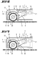
- actuators 32 for adjusting the Bristle roller vertical position are provided.
- These actuators 32 can be a bimetal element, a piezo actuator, a motor, an electrochemical actuator or be the same, both the arrangement of the actuator 32 above the Belt housing 9 according to FIG. 6 and on the underside thereof - as in FIG. 7 shown - is possible.
- These actuators also preferably do not work with one illustrated, oppositely acting spring together.
- the actuation of the actuator 32 takes place via the evaluation of the recorded Motor current and / or by evaluating the detected negative pressure, this vacuum being arranged above in the vacuum-laden suction chamber 5 Pressure sensor 33 is determined.
- the measuring device 21 processes the signals of the pressure sensor 33 and the Measurement data of the motor current for a control signal for the actuator.
- the bristle roller can be operated via an external actuation switch 34 (automatic button) 16 e.g. deliberately lifted off the ground and so on guarantee a hard floor operation or the self-regulating system activate.
- a spring or a spring-like material can have the effect of Support or dampen the actuator or protect it from damage.
- the motor needs Carpet an increased volume flow, but the bristle roller 16 accesses far into the carpet pile. To avoid damage to carpets and doing so The bristle roller will reduce the pushing forces and engine warming 16 raised accordingly. With high negative pressure and low Motor current is a dense carpet, the bristle roller 16 with their The bristles do not engage enough in the carpet pile. The bristle roller 16 is lowered which maintains the brushing effect.
Landscapes
- Engineering & Computer Science (AREA)
- Mechanical Engineering (AREA)
- Nozzles For Electric Vacuum Cleaners (AREA)
Abstract
Description
- Fig. 1
- ein erfindungsgemäßes Sauggerät in Form eines Saug-Bürstengeräts in Unteransicht;
- Fig. 2
- den schematischen Schnitt gemäß der Linie II-II in Fig. 1, eine erste Ausführungsform mit einer einstellbaren Feder betreffend;
- Fig. 3
- eine der Fig. 2 entsprechende schematische Schnittdarstellung, jedoch eine zweite Ausführungsform mit einer Exzenterscheibe betreffend;
- Fig. 4
- die dritte Ausführungsform mit einem Pneumatik-Stellelement;
- Fig. 5
- eine weitere pneumatische Ausführungsform;
- Fig. 6
- eine schematische Schnittdarstellung, eine weitere Ausführungsform mit einem Aktor betreffend;
- Fig. 7
- eine der Fig. 6 entsprechende Darstellung, jedoch eine alternative Ausführungsform mit Aktor betreffend.
Claims (18)
- Sauggerät (1), insbesondere Vorsatz oder Teil eines Elektro-Staubsaugers, vorzugsweise Saug-Bürstengerät zur Pflege von Teppichböden (20), mit einem Saugkanal (4) sowie einem Elektromotor (6) und einer oder mehreren hiervon angetriebenen Borstenwalzen (16), wobei die Borstenwalzen (16) in vertikaler Richtung (a) zur unterschiedlichen Einwirkung auf den Teppichboden (20) einstellbar beweglich gehaltert sind, dadurch gekennzeichnet, dass die Einwirkung einer Borstenwalze (16) in den Teppichboden (20) in Abhängigkeit von einem im Saugkanal (4) erfassten Unterdruck durchführbar ist.
- Sauggerät nach den Merkmalen des Oberbegriffs des Anspruchs 1, dadurch gekennzeichnet, dass die Einwirkung der Borstenwalze (16) in den Teppichboden (20) in Abhängigkeit von einem erfassten, als Parameter für einen Drehwiderstand der Borstenwalze (16) herangezogenen Motorstrom durchführbar ist.
- Sauggerät nach einem oder mehreren der vorhergehenden Ansprüche oder insbesondere danach, dadurch gekennzeichnet, dass die Einwirkung durch Änderung der Drehzahl der Borstenwalze (16) beeinflussbar ist.
- Sauggerät nach einem oder mehreren der vorhergehenden Ansprüche oder insbesondere danach, dadurch gekennzeichnet, dass die Änderung der Drehzahl der Borstenwalze (16) durch eine elektronische Drehzahlregelung des Elektromotors (6) erfolgt.
- Sauggerät nach einem oder mehreren der vorhergehenden Ansprüche oder insbesondere danach, dadurch gekennzeichnet, dass die Einwirkung durch Veränderung der Vorstandslage der Borstenwalze (16) erfolgt.
- Sauggerät nach einem oder mehreren der vorhergehenden Ansprüche oder insbesondere danach, dadurch gekennzeichnet, dass die Borstenwalze (16) in einem Vertikalschlitz gelagert ist.
- Sauggerät nach einem oder mehreren der vorhergehenden Ansprüche oder insbesondere danach, dadurch gekennzeichnet, dass die Borstenwalze (16) an einer Lagerungswippe befestigt ist.
- Sauggerät nach einem oder mehreren der vorhergehenden Ansprüche oder insbesondere danach, dadurch gekennzeichnet, dass die Vorstandslage der Borstenwalze (16) durch Änderung einer in Vertikalrichtung wirkenden Federbeaufschlagung der Borstenwalze (16) beeinflussbar ist.
- Sauggerät nach einem oder mehreren der vorhergehenden Ansprüche oder insbesondere danach, dadurch gekennzeichnet, dass die Feder als Luftfeder (30) ausgebildet ist und die Federcharakteristik durch einen jeweils erfassten Unterdruck im Saugkanal (4) eingestellt ist.
- Sauggerät nach einem oder mehreren der vorhergehenden Ansprüche oder insbesondere danach, dadurch gekennzeichnet, dass die Federbeaufschlagung an der Lagerungswippe angreift und mit einer entgegensetzt wirkenden Feder kombiniert ist.
- Sauggerät nach einem oder mehreren der vorhergehenden Ansprüche oder insbesondere danach, dadurch gekennzeichnet, dass die Lagerung der Borstenwalze (16) in Vertikalrichtung verstellbar ist.
- Sauggerät nach einem oder mehreren der vorhergehenden Ansprüche oder insbesondere danach, dadurch gekennzeichnet, dass die Verstellung durch einen Aktor (32) erfolgt.
- Sauggerät nach einem oder mehreren der vorhergehenden Ansprüche oder insbesondere danach, dadurch gekennzeichnet, dass der Aktor (32) ein Betätigungsstempel ist.
- Sauggerät nach einem oder mehreren der vorhergehenden Ansprüche oder insbesondere danach, dadurch gekennzeichnet, dass der Aktor (32) ein elektrisch ausfahrbares Element ist.
- Sauggerät nach einem oder mehreren der vorhergehenden Ansprüche oder insbesondere danach, dadurch gekennzeichnet, dass der Aktor (32) ein pneumatisch ausfahrbares Element ist.
- Sauggerät nach einem oder mehreren der vorhergehenden Ansprüche oder insbesondere danach, dadurch gekennzeichnet, dass der Aktor (32) ein Bimetallelement ist.
- Sauggerät nach einem oder mehreren der vorhergehenden Ansprüche oder insbesondere danach, dadurch gekennzeichnet, dass der Aktor (32) ein Piezoaktor ist.
- Sauggerät nach einem oder mehreren der vorhergehenden Ansprüche oder insbesondere danach, dadurch gekennzeichnet, dass der Aktor (32) ein elektrochemischer Aktor ist.
Applications Claiming Priority (4)
| Application Number | Priority Date | Filing Date | Title |
|---|---|---|---|
| DE20213835 | 2002-09-07 | ||
| DE20213835U | 2002-09-07 | ||
| DE20313354U | 2003-08-27 | ||
| DE20313354U DE20313354U1 (de) | 2002-09-07 | 2003-08-27 | Sauggerät, insbesondere Vorsatz oder Teil eines Elektro-Staubsaugers |
Publications (3)
| Publication Number | Publication Date |
|---|---|
| EP1396222A2 true EP1396222A2 (de) | 2004-03-10 |
| EP1396222A3 EP1396222A3 (de) | 2005-03-23 |
| EP1396222B1 EP1396222B1 (de) | 2010-04-14 |
Family
ID=31716749
Family Applications (1)
| Application Number | Title | Priority Date | Filing Date |
|---|---|---|---|
| EP20030020058 Expired - Lifetime EP1396222B1 (de) | 2002-09-07 | 2003-09-04 | Saugbürstengerät für einen Staubsauger |
Country Status (2)
| Country | Link |
|---|---|
| EP (1) | EP1396222B1 (de) |
| CN (1) | CN100500071C (de) |
Cited By (5)
| Publication number | Priority date | Publication date | Assignee | Title |
|---|---|---|---|---|
| EP1681002A3 (de) * | 2005-01-12 | 2006-10-11 | Vax Limited | Staubsaugerdüse mit einem rotierbaren Bürste |
| DE102010000573A1 (de) | 2010-02-26 | 2011-09-01 | Vorwerk & Co. Interholding Gmbh | Verfahren zur Leistungssteuerung eines Saug-/Kehrgeräts |
| DE102015100483A1 (de) * | 2015-01-14 | 2016-07-28 | Vorwerk & Co. Interholding Gmbh | Saugeinheit für einen Staubsauger |
| US11202543B2 (en) | 2018-01-17 | 2021-12-21 | Techtronic Floor Care Technology Limited | System and method for operating a cleaning system based on a surface to be cleaned |
| CN120348063A (zh) * | 2025-06-24 | 2025-07-22 | 福建佶龙机械科技股份有限公司 | 一种基于视觉检测的圆网印花机 |
Families Citing this family (8)
| Publication number | Priority date | Publication date | Assignee | Title |
|---|---|---|---|---|
| KR101287028B1 (ko) * | 2011-03-04 | 2013-07-17 | 한경희 | 카펫 청소기 |
| US20140157543A1 (en) | 2012-12-12 | 2014-06-12 | Electrolux Home Care Products, Inc. | Vacuum cleaner base assembly |
| US9345371B2 (en) | 2012-12-12 | 2016-05-24 | Electrolux Home Care Products, Inc. | Vacuum cleaner base assembly |
| DE102016101040A1 (de) * | 2016-01-21 | 2017-07-27 | Vorwerk & Co. Interholding Gmbh | Saugdüse für ein Saugreinigungsgerät |
| DE102017106367A1 (de) * | 2017-03-24 | 2018-09-27 | Vorwerk & Co. Interholding Gmbh | Vorsatzgerät zur Teppichreinigung |
| DE102017118378A1 (de) * | 2017-08-11 | 2019-02-14 | Vorwerk & Co. Interholding Gmbh | Bodenbearbeitungsgerät mit einem elektromotorisch angetriebenen Bodenbearbeitungselement |
| DE102018116547B4 (de) * | 2018-07-09 | 2020-08-20 | Vorwerk & Co. Interholding Gmbh | Saugdüse für einen Staubsauger zum Reinigen eines Teppichs und Staubsauger mit einer derartigen Saugdüse |
| CN110742556B (zh) * | 2019-10-24 | 2025-08-05 | 苏州金莱克精密机械有限公司 | 扫地机 |
Citations (1)
| Publication number | Priority date | Publication date | Assignee | Title |
|---|---|---|---|---|
| US4679271A (en) | 1986-03-14 | 1987-07-14 | Tennant Company | Automatic tool force compensator for a surface maintenance machine |
Family Cites Families (3)
| Publication number | Priority date | Publication date | Assignee | Title |
|---|---|---|---|---|
| JP2807883B2 (ja) * | 1987-11-17 | 1998-10-08 | アマノ株式会社 | 床面艶出機 |
| DE3913390A1 (de) * | 1989-04-24 | 1990-10-25 | Stein & Co Gmbh | Einstellvorrichtung fuer bodenpflegegeraete |
| US6123779A (en) * | 1999-06-01 | 2000-09-26 | Fantom Technologies Inc. | Pressure based sensing means for adjusting the height of an agitator in a vacuum cleaner head |
-
2003
- 2003-09-04 EP EP20030020058 patent/EP1396222B1/de not_active Expired - Lifetime
- 2003-09-08 CN CNB031566502A patent/CN100500071C/zh not_active Expired - Fee Related
Patent Citations (1)
| Publication number | Priority date | Publication date | Assignee | Title |
|---|---|---|---|---|
| US4679271A (en) | 1986-03-14 | 1987-07-14 | Tennant Company | Automatic tool force compensator for a surface maintenance machine |
Cited By (11)
| Publication number | Priority date | Publication date | Assignee | Title |
|---|---|---|---|---|
| EP1681002A3 (de) * | 2005-01-12 | 2006-10-11 | Vax Limited | Staubsaugerdüse mit einem rotierbaren Bürste |
| GB2422090B (en) * | 2005-01-12 | 2008-07-02 | Techtronic Ind Co Ltd | Head for a suction cleaner |
| RU2402256C2 (ru) * | 2005-01-12 | 2010-10-27 | Вэкс Лимитид | Насадка для мусороуборочной машины вакуумного действия |
| US7849558B2 (en) | 2005-01-12 | 2010-12-14 | Bengt Ivar Anders Ivarsson | Head for a suction cleaner |
| DE102010000573A1 (de) | 2010-02-26 | 2011-09-01 | Vorwerk & Co. Interholding Gmbh | Verfahren zur Leistungssteuerung eines Saug-/Kehrgeräts |
| DE102010000573B4 (de) | 2010-02-26 | 2022-06-23 | Vorwerk & Co. Interholding Gmbh | Verfahren zur Leistungssteuerung eines Saug-/Kehrgeräts |
| DE102015100483A1 (de) * | 2015-01-14 | 2016-07-28 | Vorwerk & Co. Interholding Gmbh | Saugeinheit für einen Staubsauger |
| DE102015100483B4 (de) | 2015-01-14 | 2024-04-18 | Vorwerk & Co. Interholding Gmbh | Saugeinheit für einen Staubsauger |
| US11202543B2 (en) | 2018-01-17 | 2021-12-21 | Techtronic Floor Care Technology Limited | System and method for operating a cleaning system based on a surface to be cleaned |
| US11839349B2 (en) | 2018-01-17 | 2023-12-12 | Techtronic Floor Care Technology Limited | System and method for operating a cleaning system based on a surface to be cleaned |
| CN120348063A (zh) * | 2025-06-24 | 2025-07-22 | 福建佶龙机械科技股份有限公司 | 一种基于视觉检测的圆网印花机 |
Also Published As
| Publication number | Publication date |
|---|---|
| EP1396222B1 (de) | 2010-04-14 |
| CN100500071C (zh) | 2009-06-17 |
| CN1493245A (zh) | 2004-05-05 |
| EP1396222A3 (de) | 2005-03-23 |
Similar Documents
| Publication | Publication Date | Title |
|---|---|---|
| EP1396222A2 (de) | Sauggerät, insbesondere Vorsatz oder Teil eines Elektro-Staubsaugers | |
| DE102010000573B4 (de) | Verfahren zur Leistungssteuerung eines Saug-/Kehrgeräts | |
| EP1713370B1 (de) | Bodendüse für einen staubsauger | |
| EP0394641B1 (de) | Einstellvorrichtung für Bodenpflegegeräte | |
| EP3569124B1 (de) | Reinigungsgerät | |
| EP0552652B1 (de) | Bodendüse für Staubsauger | |
| EP0630604B1 (de) | Bodensauggerät, insbesondere Vorsatz oder Teil eines Elektro-Staubsaugers | |
| EP3430961B1 (de) | Bodenbearbeitungsgerät mit einem motorisch angetriebenen bodenbearbeitungselement | |
| EP3024370B1 (de) | Bodenreinigungsmaschine und einstellverfahren | |
| DE102012101133A1 (de) | Sauggerät, insbesondere Vorsatz oder Teil eines Elektro-Staubsaugers | |
| DE20313354U1 (de) | Sauggerät, insbesondere Vorsatz oder Teil eines Elektro-Staubsaugers | |
| DE102004014252A1 (de) | Verfahren zum Betreiben eines Staubsaugers mit einer Saugdüse sowie Staubsauger mit einer Saugdüse | |
| EP3266299B1 (de) | Ballenpresse | |
| DE102018116547B4 (de) | Saugdüse für einen Staubsauger zum Reinigen eines Teppichs und Staubsauger mit einer derartigen Saugdüse | |
| DE202018104549U1 (de) | Saugdüse für einen Staubsauger sowie Staubsauger zum Reinigen eines Bodenbelages | |
| EP1064162B1 (de) | Verfahren und vorrichtung zum betreiben eines verstellantriebs in einem kraftfahrzeug | |
| DE102012109627A1 (de) | Bodenreinigungsgerät | |
| EP3417756A1 (de) | Bodenreinigungsmaschine mit bürstenandruckverstellung | |
| EP3536834B1 (de) | Ballenöffner | |
| WO2005082220A1 (de) | Bodendüse für einen staubsauger | |
| DE102015102333B4 (de) | Kehrmaschine und Verfahren zum Nachstellen einer Kehrwalze einer Kehrmaschine | |
| DE60011805T2 (de) | Reinigungsvorrichtung mit auswechselbarer bürste | |
| DE102017106367A1 (de) | Vorsatzgerät zur Teppichreinigung | |
| DE102017102466A1 (de) | Saugdüse mit Bodenanpassung | |
| DE202024101407U1 (de) | Reinigungsbaugruppe und Reinigungsroboter |
Legal Events
| Date | Code | Title | Description |
|---|---|---|---|
| PUAI | Public reference made under article 153(3) epc to a published international application that has entered the european phase |
Free format text: ORIGINAL CODE: 0009012 |
|
| AK | Designated contracting states |
Kind code of ref document: A2 Designated state(s): AT BE BG CH CY CZ DE DK EE ES FI FR GB GR HU IE IT LI LU MC NL PT RO SE SI SK TR |
|
| AX | Request for extension of the european patent |
Extension state: AL LT LV MK |
|
| PUAL | Search report despatched |
Free format text: ORIGINAL CODE: 0009013 |
|
| AK | Designated contracting states |
Kind code of ref document: A3 Designated state(s): AT BE BG CH CY CZ DE DK EE ES FI FR GB GR HU IE IT LI LU MC NL PT RO SE SI SK TR |
|
| AX | Request for extension of the european patent |
Extension state: AL LT LV MK |
|
| RIC1 | Information provided on ipc code assigned before grant |
Ipc: 7A 47L 9/28 B Ipc: 7A 47L 5/34 B Ipc: 7A 47L 9/04 A |
|
| 17P | Request for examination filed |
Effective date: 20050728 |
|
| AKX | Designation fees paid |
Designated state(s): AT BE BG CH CY CZ DE DK EE ES FI FR GB GR HU IE IT LI LU MC NL PT RO SE SI SK TR |
|
| 17Q | First examination report despatched |
Effective date: 20080221 |
|
| RTI1 | Title (correction) |
Free format text: BRUSH SUCTION DEVICE FOR A VACUUM CLEANER |
|
| GRAP | Despatch of communication of intention to grant a patent |
Free format text: ORIGINAL CODE: EPIDOSNIGR1 |
|
| GRAS | Grant fee paid |
Free format text: ORIGINAL CODE: EPIDOSNIGR3 |
|
| GRAA | (expected) grant |
Free format text: ORIGINAL CODE: 0009210 |
|
| AK | Designated contracting states |
Kind code of ref document: B1 Designated state(s): AT BE BG CH CY CZ DE DK EE ES FI FR GB GR HU IE IT LI LU MC NL PT RO SE SI SK TR |
|
| REG | Reference to a national code |
Ref country code: GB Ref legal event code: FG4D Free format text: NOT ENGLISH |
|
| REG | Reference to a national code |
Ref country code: CH Ref legal event code: EP |
|
| REG | Reference to a national code |
Ref country code: IE Ref legal event code: FG4D Free format text: LANGUAGE OF EP DOCUMENT: GERMAN |
|
| REF | Corresponds to: |
Ref document number: 50312605 Country of ref document: DE Date of ref document: 20100527 Kind code of ref document: P |
|
| REG | Reference to a national code |
Ref country code: NL Ref legal event code: VDEP Effective date: 20100414 |
|
| PG25 | Lapsed in a contracting state [announced via postgrant information from national office to epo] |
Ref country code: NL Free format text: LAPSE BECAUSE OF FAILURE TO SUBMIT A TRANSLATION OF THE DESCRIPTION OR TO PAY THE FEE WITHIN THE PRESCRIBED TIME-LIMIT Effective date: 20100414 Ref country code: ES Free format text: LAPSE BECAUSE OF FAILURE TO SUBMIT A TRANSLATION OF THE DESCRIPTION OR TO PAY THE FEE WITHIN THE PRESCRIBED TIME-LIMIT Effective date: 20100725 Ref country code: SE Free format text: LAPSE BECAUSE OF FAILURE TO SUBMIT A TRANSLATION OF THE DESCRIPTION OR TO PAY THE FEE WITHIN THE PRESCRIBED TIME-LIMIT Effective date: 20100414 |
|
| REG | Reference to a national code |
Ref country code: IE Ref legal event code: FD4D |
|
| PG25 | Lapsed in a contracting state [announced via postgrant information from national office to epo] |
Ref country code: SI Free format text: LAPSE BECAUSE OF FAILURE TO SUBMIT A TRANSLATION OF THE DESCRIPTION OR TO PAY THE FEE WITHIN THE PRESCRIBED TIME-LIMIT Effective date: 20100414 Ref country code: FI Free format text: LAPSE BECAUSE OF FAILURE TO SUBMIT A TRANSLATION OF THE DESCRIPTION OR TO PAY THE FEE WITHIN THE PRESCRIBED TIME-LIMIT Effective date: 20100414 |
|
| PG25 | Lapsed in a contracting state [announced via postgrant information from national office to epo] |
Ref country code: GR Free format text: LAPSE BECAUSE OF FAILURE TO SUBMIT A TRANSLATION OF THE DESCRIPTION OR TO PAY THE FEE WITHIN THE PRESCRIBED TIME-LIMIT Effective date: 20100715 Ref country code: CY Free format text: LAPSE BECAUSE OF FAILURE TO SUBMIT A TRANSLATION OF THE DESCRIPTION OR TO PAY THE FEE WITHIN THE PRESCRIBED TIME-LIMIT Effective date: 20100414 |
|
| PG25 | Lapsed in a contracting state [announced via postgrant information from national office to epo] |
Ref country code: IE Free format text: LAPSE BECAUSE OF FAILURE TO SUBMIT A TRANSLATION OF THE DESCRIPTION OR TO PAY THE FEE WITHIN THE PRESCRIBED TIME-LIMIT Effective date: 20100414 Ref country code: PT Free format text: LAPSE BECAUSE OF FAILURE TO SUBMIT A TRANSLATION OF THE DESCRIPTION OR TO PAY THE FEE WITHIN THE PRESCRIBED TIME-LIMIT Effective date: 20100816 Ref country code: DK Free format text: LAPSE BECAUSE OF FAILURE TO SUBMIT A TRANSLATION OF THE DESCRIPTION OR TO PAY THE FEE WITHIN THE PRESCRIBED TIME-LIMIT Effective date: 20100414 Ref country code: EE Free format text: LAPSE BECAUSE OF FAILURE TO SUBMIT A TRANSLATION OF THE DESCRIPTION OR TO PAY THE FEE WITHIN THE PRESCRIBED TIME-LIMIT Effective date: 20100414 |
|
| PLBE | No opposition filed within time limit |
Free format text: ORIGINAL CODE: 0009261 |
|
| STAA | Information on the status of an ep patent application or granted ep patent |
Free format text: STATUS: NO OPPOSITION FILED WITHIN TIME LIMIT |
|
| PG25 | Lapsed in a contracting state [announced via postgrant information from national office to epo] |
Ref country code: RO Free format text: LAPSE BECAUSE OF FAILURE TO SUBMIT A TRANSLATION OF THE DESCRIPTION OR TO PAY THE FEE WITHIN THE PRESCRIBED TIME-LIMIT Effective date: 20100414 Ref country code: SK Free format text: LAPSE BECAUSE OF FAILURE TO SUBMIT A TRANSLATION OF THE DESCRIPTION OR TO PAY THE FEE WITHIN THE PRESCRIBED TIME-LIMIT Effective date: 20100414 Ref country code: CZ Free format text: LAPSE BECAUSE OF FAILURE TO SUBMIT A TRANSLATION OF THE DESCRIPTION OR TO PAY THE FEE WITHIN THE PRESCRIBED TIME-LIMIT Effective date: 20100414 |
|
| 26N | No opposition filed |
Effective date: 20110117 |
|
| BERE | Be: lapsed |
Owner name: VORWERK & CO. INTERHOLDING G.M.B.H. Effective date: 20100930 |
|
| PG25 | Lapsed in a contracting state [announced via postgrant information from national office to epo] |
Ref country code: MC Free format text: LAPSE BECAUSE OF NON-PAYMENT OF DUE FEES Effective date: 20100930 |
|
| REG | Reference to a national code |
Ref country code: CH Ref legal event code: PL |
|
| GBPC | Gb: european patent ceased through non-payment of renewal fee |
Effective date: 20100904 |
|
| REG | Reference to a national code |
Ref country code: FR Ref legal event code: ST Effective date: 20110531 |
|
| PG25 | Lapsed in a contracting state [announced via postgrant information from national office to epo] |
Ref country code: LI Free format text: LAPSE BECAUSE OF NON-PAYMENT OF DUE FEES Effective date: 20100930 Ref country code: BE Free format text: LAPSE BECAUSE OF NON-PAYMENT OF DUE FEES Effective date: 20100930 Ref country code: FR Free format text: LAPSE BECAUSE OF NON-PAYMENT OF DUE FEES Effective date: 20100930 Ref country code: CH Free format text: LAPSE BECAUSE OF NON-PAYMENT OF DUE FEES Effective date: 20100930 |
|
| PG25 | Lapsed in a contracting state [announced via postgrant information from national office to epo] |
Ref country code: GB Free format text: LAPSE BECAUSE OF NON-PAYMENT OF DUE FEES Effective date: 20100904 |
|
| PG25 | Lapsed in a contracting state [announced via postgrant information from national office to epo] |
Ref country code: AT Free format text: LAPSE BECAUSE OF NON-PAYMENT OF DUE FEES Effective date: 20100904 |
|
| PG25 | Lapsed in a contracting state [announced via postgrant information from national office to epo] |
Ref country code: BG Free format text: LAPSE BECAUSE OF FAILURE TO SUBMIT A TRANSLATION OF THE DESCRIPTION OR TO PAY THE FEE WITHIN THE PRESCRIBED TIME-LIMIT Effective date: 20100414 Ref country code: HU Free format text: LAPSE BECAUSE OF FAILURE TO SUBMIT A TRANSLATION OF THE DESCRIPTION OR TO PAY THE FEE WITHIN THE PRESCRIBED TIME-LIMIT Effective date: 20101015 Ref country code: LU Free format text: LAPSE BECAUSE OF NON-PAYMENT OF DUE FEES Effective date: 20100904 |
|
| PG25 | Lapsed in a contracting state [announced via postgrant information from national office to epo] |
Ref country code: TR Free format text: LAPSE BECAUSE OF FAILURE TO SUBMIT A TRANSLATION OF THE DESCRIPTION OR TO PAY THE FEE WITHIN THE PRESCRIBED TIME-LIMIT Effective date: 20100414 |
|
| PG25 | Lapsed in a contracting state [announced via postgrant information from national office to epo] |
Ref country code: BG Free format text: LAPSE BECAUSE OF FAILURE TO SUBMIT A TRANSLATION OF THE DESCRIPTION OR TO PAY THE FEE WITHIN THE PRESCRIBED TIME-LIMIT Effective date: 20100714 |
|
| PGFP | Annual fee paid to national office [announced via postgrant information from national office to epo] |
Ref country code: DE Payment date: 20150916 Year of fee payment: 13 |
|
| PGFP | Annual fee paid to national office [announced via postgrant information from national office to epo] |
Ref country code: IT Payment date: 20150924 Year of fee payment: 13 |
|
| REG | Reference to a national code |
Ref country code: DE Ref legal event code: R119 Ref document number: 50312605 Country of ref document: DE |
|
| PG25 | Lapsed in a contracting state [announced via postgrant information from national office to epo] |
Ref country code: DE Free format text: LAPSE BECAUSE OF NON-PAYMENT OF DUE FEES Effective date: 20170401 |
|
| PG25 | Lapsed in a contracting state [announced via postgrant information from national office to epo] |
Ref country code: IT Free format text: LAPSE BECAUSE OF NON-PAYMENT OF DUE FEES Effective date: 20160904 |