EP1396301A2 - Dispositif de serrage pour des pièces ou outils - Google Patents
Dispositif de serrage pour des pièces ou outils Download PDFInfo
- Publication number
- EP1396301A2 EP1396301A2 EP03020060A EP03020060A EP1396301A2 EP 1396301 A2 EP1396301 A2 EP 1396301A2 EP 03020060 A EP03020060 A EP 03020060A EP 03020060 A EP03020060 A EP 03020060A EP 1396301 A2 EP1396301 A2 EP 1396301A2
- Authority
- EP
- European Patent Office
- Prior art keywords
- clamping
- clamping device
- housing
- compensation
- piezo stack
- Prior art date
- Legal status (The legal status is an assumption and is not a legal conclusion. Google has not performed a legal analysis and makes no representation as to the accuracy of the status listed.)
- Withdrawn
Links
Images



Classifications
-
- B—PERFORMING OPERATIONS; TRANSPORTING
- B23—MACHINE TOOLS; METAL-WORKING NOT OTHERWISE PROVIDED FOR
- B23B—TURNING; BORING
- B23B31/00—Chucks; Expansion mandrels; Adaptations thereof for remote control
- B23B31/02—Chucks
- B23B31/10—Chucks characterised by the retaining or gripping devices or their immediate operating means
- B23B31/12—Chucks with simultaneously-acting jaws, whether or not also individually adjustable
- B23B31/16—Chucks with simultaneously-acting jaws, whether or not also individually adjustable moving radially
- B23B31/16158—Jaws movement actuated by coaxial conical surfaces
- B23B31/16162—Details of the jaws
- B23B31/16175—Individually adjustable jaws
-
- B—PERFORMING OPERATIONS; TRANSPORTING
- B23—MACHINE TOOLS; METAL-WORKING NOT OTHERWISE PROVIDED FOR
- B23B—TURNING; BORING
- B23B31/00—Chucks; Expansion mandrels; Adaptations thereof for remote control
- B23B31/02—Chucks
- B23B31/10—Chucks characterised by the retaining or gripping devices or their immediate operating means
- B23B31/117—Retention by friction only, e.g. using springs, resilient sleeves, tapers
- B23B31/1173—Retention by friction only, e.g. using springs, resilient sleeves, tapers using springs
-
- B—PERFORMING OPERATIONS; TRANSPORTING
- B23—MACHINE TOOLS; METAL-WORKING NOT OTHERWISE PROVIDED FOR
- B23B—TURNING; BORING
- B23B31/00—Chucks; Expansion mandrels; Adaptations thereof for remote control
- B23B31/02—Chucks
- B23B31/32—Chucks with jaws carried by diaphragm
-
- B—PERFORMING OPERATIONS; TRANSPORTING
- B23—MACHINE TOOLS; METAL-WORKING NOT OTHERWISE PROVIDED FOR
- B23B—TURNING; BORING
- B23B2260/00—Details of constructional elements
- B23B2260/108—Piezoelectric elements
Definitions
- the invention relates to a device for clamping workpieces or tools, preferably for rotating machining.
- tensioning devices by hand or by electrodynamic, pneumatic or hydraulic drives operated can be. These drives work in for rotating machining usually on rotationally symmetrically arranged clamping jaws which include workpieces or tools in the radial direction. there the jaws usually work synchronously controlled by a drive.
- piezo stacks as a drive for clamping jaws is known in principle.
- the piezo stack enables practically arbitrary delivery of path and / or force, generates very high actuating forces and energies with the smallest construction volume and does not require any energy to hold a position.
- the main disadvantage of the piezo stack is the short travel range of 0.1 to 0.2% of the stack length.
- the arrangements of piezo drives disclosed in DE 39 29 010 A1 have some disadvantages which impair the function significantly and can even prevent them under extreme conditions.
- the travel of actuators is 0.1 to 0.2% of the stack length.
- the path length of approx. 1 mm specified in DE 39 29 010 A1 is therefore completely unrealistic and the disclosure cannot be reworked.
- the typical, achievable travel ranges are, for example, 40 ⁇ m, a stack length of 31 mm being necessary for their production.
- the piezo stacks provided for clamping the workpiece are arranged radially, which has the disadvantage that large adjustment strokes are only possible with very large diameters of the clamping tool.
- a further disadvantage is that the arrangements have many individual parts and transitions in the power flow, on which shape deviations, tolerance tolerances, bearing and backlash occur due to surface pressures, which significantly impair the function due to the short travel ranges of the piezo drives.
- temperature differences between +10 ° C and +80 ° C and more occur during processing due to the processing heat, cooling or fluctuations in the ambient temperature.
- the different coefficients of thermal expansion between the housing material (usually steel) and the piezo stack lead to thermal changes in length which are in the range of 50% of the piezo expansion. This leads to a considerable reduction in the clamping forces and in extreme cases to loosening the clamped part.
- the essence of the present invention is that the device has piezoelectric drives with compensation bodies, carry the transmission / translation function with regard to distance and force between the piezoelectric drive and the tool or workpiece to be clamped, and that the device performs a temperature compensation function due to the material composition and - Dimensioning of the compensation body can have.
- the device according to the invention has an arrangement of the piezo stack in the axial direction of the body to be clamped. This enables a large length of the piezo stack and thus large piezo positioning paths. Alternatively, a linear or circular arrangement of several piezo stacks is possible, which enables large piezo cross sections and large actuating forces for clamping tools or workpieces.
- the transfer / translation function of the device according to the invention enables both a deflection of the force flow from parallel on the drive to perpendicular on the clamping body, as well as an influencing of the crane-travel characteristic (travel or force translation).
- the advantage of the device according to the invention is that it has a compact structure in the radial direction, a central one has free passage, large actuating forces at sufficiently high Travel paths realized, with variation of travel and positioning force The same actuator can be used.
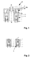
- a device V according to the invention with a geometric axis X-X consists of at least two drive units A in mirror symmetry or radially symmetrical arrangement, each with a clamping unit SE, wherein each of these drive units A, as shown in Fig. 1, from at least a piezo stack 1 with connecting lines 2, which is on his one end 11 connected to a compensation body 4 and from is surrounded by a housing 3, the compensation body 4 via a push rod 5 with a shaft 71 of a clamping jaw 7 around one Angle ⁇ is pivotally connected via solid joints 51, 52.
- the piezo stack 1 is in the axial direction of the clamping body 8 stored and cohesively with the compensation body 4 and Push rod 5 connected.
- two of these drive units A are, as shown in FIG. 1, arranged mirror-symmetrically to each other to form a device of the type so that between the symmetrically arranged jaws 7 of the Housing 3 a clamping body 8 can be clamped.
- the piezo stack 1 of one drive unit A or both drive units A is electrically controlled via the connecting lines 2, it expands in the axial direction.
- the inclination of the push rod 5 translates the movement of the piezo stack 1 and converts it into a radially directed movement by the parallelogram arrangement of the legs 6 and 6 'to that of the shaft 71.
- the drive units A are blocked and the holding force is built up in proportion to the drive stiffness.
- the leg 6 ' can also be dispensed with, as shown in FIGS. 4a and 4b.
- the legs can also, as shown in Fig. 5, be arranged opposite to the drive. 1, 4 and 5, path translations of 10-fold and more can be achieved.
- FIG. 2 shows the thermal structure according to the invention compensated construction of a drive unit A.
- the piezo stack 1 is installed in a U-shaped housing 3, for example made of steel, and is preloaded, for example, with disc springs 9.
- a U-shaped housing 3 for example made of steel
- its thermal expansion also depends on the operating conditions, the preload pressure and the electrical control. In the stack arrangements used, it is smaller than that of the steel housing.
- the expansion coefficient of this steel housing is 7.5 ⁇ 10 -6 / K.
- a compensation body 4 made of a material with a large thermal expansion, for example aluminum (expansion coefficient at 23 * 10 -6 / K), is selected in its length such that the sum of the thermal expansion of the piezo stack 1 and the compensation body 4 is just equal to that Elongation of the housing 3 and thus no thermally induced movement occurs on the clamping jaw 7.
- FIG. 3a and b show how a plurality of drive units A are arranged in a tubular housing 3 with a U-shaped cross section to form a device and are divided into individual clamping segments SP in a rotationally symmetrical manner about an axis XX.
- Each clamping segment SP is formed by an output plate 10, which is also a clamping jaw, on which one or more identical drive units A each work in parallel, but can also be formed by a common compensation body 4.
- Each clamping segment SP can optionally be controlled independently of the others and compensate for small eccentricities or, if necessary, generate them in a defined manner.
- a single ring segment is also possible if all clamping jaws 7 are to work exclusively in a symmetrical and synchronous manner.
- Two in the fig. 3a and b devices work together in opposite directions to clamp a clamping body in the axial direction.
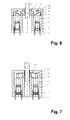
- the drive wedge 11 is made from a non-segmented ring, the bearing 13 'can be omitted. At least two radially symmetrical driven wedges 12 with clamping jaws 7 are provided on the driven side.
- FIGS. 7 and 8 Another variant of the transmission mechanism, which is characterized by the use of wear parts that are very easy to manufacture and replace, is shown in FIGS. 7 and 8. It is particularly suitable for the generation of large clamping forces.
- the basic element of this transmission mechanism is the plate-shaped spring washer 14, 14 ′ with a recess 17, which is radially slotted from the inside and is shown in FIG. 7. As shown in FIGS. 8 and 9, this spring washer 14, 14 'or a plurality of spring washers 14, 14' are layered one above the other, possibly separated by spacer rings 15 and 16, installed in the housing 3.
- Typical angles of attack of 15 - 30 ° result in reduction ratios of 0.27 - 0.6 or force ratios from 3.7 to 1.7.
Landscapes
- Engineering & Computer Science (AREA)
- Mechanical Engineering (AREA)
- General Electrical Machinery Utilizing Piezoelectricity, Electrostriction Or Magnetostriction (AREA)
- Jigs For Machine Tools (AREA)
- Machine Tool Units (AREA)
Applications Claiming Priority (2)
| Application Number | Priority Date | Filing Date | Title |
|---|---|---|---|
| DE2002141476 DE10241476A1 (de) | 2002-09-05 | 2002-09-05 | Vorrichtung zum Spannen von Werkstücken oder Werkzeugen |
| DE10241476 | 2002-09-05 |
Publications (2)
| Publication Number | Publication Date |
|---|---|
| EP1396301A2 true EP1396301A2 (fr) | 2004-03-10 |
| EP1396301A3 EP1396301A3 (fr) | 2006-05-17 |
Family
ID=31502466
Family Applications (1)
| Application Number | Title | Priority Date | Filing Date |
|---|---|---|---|
| EP03020060A Withdrawn EP1396301A3 (fr) | 2002-09-05 | 2003-09-04 | Dispositif de serrage pour des pièces ou outils |
Country Status (2)
| Country | Link |
|---|---|
| EP (1) | EP1396301A3 (fr) |
| DE (1) | DE10241476A1 (fr) |
Cited By (5)
| Publication number | Priority date | Publication date | Assignee | Title |
|---|---|---|---|---|
| WO2005063447A1 (fr) * | 2003-12-23 | 2005-07-14 | Franz Haimer Maschinenbau Kg | Dispositif de serrage pourvu d'au moins un actionneur électromécanique en tant qu'élément de serrage |
| EP1604774A1 (fr) * | 2004-06-11 | 2005-12-14 | Tornos S.A. | Pince actionnée par un organe piézoélectrique |
| EP1629937A1 (fr) * | 2004-08-26 | 2006-03-01 | Schunk GmbH & Co. KG Spann- und Greiftechnik | Procédé d'assemblage des deux pièces et système des pièces pour la mise en oeuvre de ce procédé |
| WO2014135637A1 (fr) * | 2013-03-06 | 2014-09-12 | Hans-Juergen Tuerk | Dispositif de serrage |
| CN105478813A (zh) * | 2016-01-04 | 2016-04-13 | 宁波大学 | 一种智能补偿避振车刀及其控制系统 |
Families Citing this family (1)
| Publication number | Priority date | Publication date | Assignee | Title |
|---|---|---|---|---|
| CN108809143B (zh) * | 2018-04-27 | 2020-09-15 | 浙江大学 | 一种压电堆垛驱动的纳米钳子 |
Family Cites Families (6)
| Publication number | Priority date | Publication date | Assignee | Title |
|---|---|---|---|---|
| DE3306526A1 (de) * | 1983-02-24 | 1984-08-30 | Rudi 4018 Langenfeld Kirst | Greifvorrichtung |
| DE3929010A1 (de) * | 1988-09-10 | 1990-04-12 | Smw Spanneinrichtungen | Haltevorrichtung |
| DE19644502C2 (de) * | 1996-10-25 | 2002-04-25 | Fraunhofer Ges Forschung | Greifervorrichtung für die Mikromontage kleiner Werkstücke mit wenigstens zwei Greiferelementen |
| EP0999004B1 (fr) * | 1998-11-02 | 2006-07-12 | Index-Werke Gmbh & Co. Kg Hahn & Tessky | Mandrin pour une machine-outil |
| DE10026895C2 (de) * | 1999-09-27 | 2002-03-14 | Fraunhofer Ges Forschung | Feinbohrwerkzeug |
| DE10042941A1 (de) * | 2000-08-31 | 2002-03-21 | Siemens Ag | Piezoaktor und Verfahren zur Herstellung eines Piezoaktors |
-
2002
- 2002-09-05 DE DE2002141476 patent/DE10241476A1/de not_active Ceased
-
2003
- 2003-09-04 EP EP03020060A patent/EP1396301A3/fr not_active Withdrawn
Cited By (6)
| Publication number | Priority date | Publication date | Assignee | Title |
|---|---|---|---|---|
| WO2005063447A1 (fr) * | 2003-12-23 | 2005-07-14 | Franz Haimer Maschinenbau Kg | Dispositif de serrage pourvu d'au moins un actionneur électromécanique en tant qu'élément de serrage |
| EP1604774A1 (fr) * | 2004-06-11 | 2005-12-14 | Tornos S.A. | Pince actionnée par un organe piézoélectrique |
| EP1629937A1 (fr) * | 2004-08-26 | 2006-03-01 | Schunk GmbH & Co. KG Spann- und Greiftechnik | Procédé d'assemblage des deux pièces et système des pièces pour la mise en oeuvre de ce procédé |
| WO2014135637A1 (fr) * | 2013-03-06 | 2014-09-12 | Hans-Juergen Tuerk | Dispositif de serrage |
| CN105478813A (zh) * | 2016-01-04 | 2016-04-13 | 宁波大学 | 一种智能补偿避振车刀及其控制系统 |
| CN105478813B (zh) * | 2016-01-04 | 2017-12-26 | 宁波大学 | 一种智能补偿避振车刀及其控制系统 |
Also Published As
| Publication number | Publication date |
|---|---|
| DE10241476A1 (de) | 2004-03-18 |
| EP1396301A3 (fr) | 2006-05-17 |
Similar Documents
| Publication | Publication Date | Title |
|---|---|---|
| DE102008029161B3 (de) | Lateral verstellbare optische Fassung mit Kniehebelmanipulatoreinheiten | |
| WO1996019836A1 (fr) | Element d'entrainement ou de reglage a actionnement piezo-electrique | |
| EP3430652A1 (fr) | Entraînement piézoélectrique | |
| EP2590315A1 (fr) | Dispositif d'entraînement | |
| EP1314210B1 (fr) | Actionneur piezo-electrique et son procede de production | |
| EP3717801B1 (fr) | Mécanisme d'entraînement à vis sans fin | |
| EP1396301A2 (fr) | Dispositif de serrage pour des pièces ou outils | |
| EP2887513B1 (fr) | Système de moteur linéaire et machine-outil dotée d'un système de moteur linéaire | |
| DE102010035264A1 (de) | Vorrichtung zur Axialspieleinstellung an einem Schrägwälzlager mit radial wirkenden Piezo-Aktuatoren | |
| EP1917458A1 (fr) | Organe de reglage lineaire notamment destine a la telecommande de composants reglables de modeles de soufflerie | |
| EP1384273B1 (fr) | Dispositif pour transmettre une deviation d'un actionneur | |
| EP2915754B1 (fr) | Dispositif de retenue et d'alignement d'une charge utile, en particulier un composant spatial | |
| DE102005028366A1 (de) | Bohrstange | |
| DE102018129516A1 (de) | Kugelgewindetrieb mit einstellbarer Vorspannung | |
| DE20220800U1 (de) | Piezoelektrisches Aktorsystem | |
| DE102020109685A1 (de) | Spannelement und Spannvorrichtung | |
| EP1590880B1 (fr) | Dispositif servant a transmettre une deviation d'un actionneur | |
| EP1908990A2 (fr) | Dispositif de transformation d'un mouvement rotatif en mouvement axial | |
| WO2005063447A1 (fr) | Dispositif de serrage pourvu d'au moins un actionneur électromécanique en tant qu'élément de serrage | |
| EP3301730B1 (fr) | Convertisseur d'énergie | |
| DE102018217412A1 (de) | Optische Anordnung mit einer Transportsicherung | |
| EP3915189B1 (fr) | Entraînement linéaire électromécanique | |
| EP1467111A2 (fr) | Methode pour ajuster la prétension ou le jeu d'un palier | |
| DE19824839C1 (de) | Vorrichtung zur Ausübung und/oder Einstellung einer Kraft auf eine Antriebswelle | |
| EP2130237B1 (fr) | Système de positionnement pour table micro-ajustée |
Legal Events
| Date | Code | Title | Description |
|---|---|---|---|
| PUAI | Public reference made under article 153(3) epc to a published international application that has entered the european phase |
Free format text: ORIGINAL CODE: 0009012 |
|
| AK | Designated contracting states |
Kind code of ref document: A2 Designated state(s): AT BE BG CH CY CZ DE DK EE ES FI FR GB GR HU IE IT LI LU MC NL PT RO SE SI SK TR |
|
| AX | Request for extension of the european patent |
Extension state: AL LT LV MK |
|
| PUAL | Search report despatched |
Free format text: ORIGINAL CODE: 0009013 |
|
| AK | Designated contracting states |
Kind code of ref document: A3 Designated state(s): AT BE BG CH CY CZ DE DK EE ES FI FR GB GR HU IE IT LI LU MC NL PT RO SE SI SK TR |
|
| AX | Request for extension of the european patent |
Extension state: AL LT LV MK |
|
| AKX | Designation fees paid |
Designated state(s): AT BE BG CH CY CZ DE DK EE ES FI FR GB GR HU IE IT LI LU MC NL PT RO SE SI SK TR |
|
| STAA | Information on the status of an ep patent application or granted ep patent |
Free format text: STATUS: THE APPLICATION IS DEEMED TO BE WITHDRAWN |
|
| 18D | Application deemed to be withdrawn |
Effective date: 20061118 |