EP1396312B9 - Roue centrifuge pour un appareil de sablage - Google Patents
Roue centrifuge pour un appareil de sablage Download PDFInfo
- Publication number
- EP1396312B9 EP1396312B9 EP03018006A EP03018006A EP1396312B9 EP 1396312 B9 EP1396312 B9 EP 1396312B9 EP 03018006 A EP03018006 A EP 03018006A EP 03018006 A EP03018006 A EP 03018006A EP 1396312 B9 EP1396312 B9 EP 1396312B9
- Authority
- EP
- European Patent Office
- Prior art keywords
- disk
- blast wheel
- blades
- blasting
- wheel according
- Prior art date
- Legal status (The legal status is an assumption and is not a legal conclusion. Google has not performed a legal analysis and makes no representation as to the accuracy of the status listed.)
- Expired - Lifetime
Links
Images


Classifications
-
- B—PERFORMING OPERATIONS; TRANSPORTING
- B24—GRINDING; POLISHING
- B24C—ABRASIVE OR RELATED BLASTING WITH PARTICULATE MATERIAL
- B24C5/00—Devices or accessories for generating abrasive blasts
- B24C5/06—Impeller wheels; Rotor blades therefor
- B24C5/062—Rotor blades or vanes; Locking means therefor
Definitions
- the present invention relates to a blast wheel for a blasting device for surface treatment of Workpieces, wherein the blast wheel has a base disk, which is connectable to a flange of a drive shaft, and a plurality of detachably connected to the base disk Having centrifugal blades, the base disk per Centrifugal bucket has a receiving groove, each Slingshot a widened, in the receiving groove having matching foot part and wherein locking means for mutual releasable fixation of the base disk and Slings are provided.
- a blast wheel of the aforementioned type is known from DE-A-2 161 888.
- According to this prior art has the base disc T-shaped or dovetailed Grooves for receiving the centrifugal blades. These Grooves for the centrifugal blades are in the radial direction open to the outside, so that the centrifugal blades in Radial direction separated from the base disk to the outside and radially inward with the base disk can be connected. Get inside the Centrifugal blades a stop by a flange, the concentric with the drive shaft connected to this is. So that the centrifugal blades their position even at Retain rotation of the blast wheel, a backup is done the spinning blades by each skid blades at least one screw.
- This screw for fixation the relevant centrifugal blade runs coaxially here through a larger diameter screw, respectively the base disk with the flange of the drive shaft combines.
- a disadvantage is in this known state the technique considered that the manufacture of the base disk due to the undercut groove provided therein relative is expensive.
- a Scooter blade from its holder with the base disk can be removed when the fixation screw unintentionally for the relevant centrifugal blade dissolves or due to the high load of centrifugal forces breaks or shears off.
- a blast wheel of this type in which the attachment of the Scooter blades by means of an additional, with the Base disc releasably connectable under entrapment of the foot parts Cover disc is made, document US 5 888 125.
- the Task a blast wheel of the type mentioned create that avoids the disadvantages set out and at a particularly safe and durable down the Spinning blades on the remaining spinner reached is and at the same time the assembly and disassembly of the Sling blades are easy and quick to carry out should. It should, as well as in the above cited state of Technique, each skimmer blade only at a single in Radial direction extending edge with the rest of the blower be connected.
- centrifugal blades each with their Foot part between the base disk and the cover disk be held clamped.
- very high centrifugal forces are for the most part taken up by the base disk.
- the grooves in the ground disk in which the foot parts the centrifugal blades are arranged, in front of each the outer circumference of the base disk ends here is a particularly stable construction and thus particularly safe Mounting the centrifugal blades with respect to the reached occurring centrifugal forces.
- the foot part of each Scoop seen in cross-section is T-shaped and that the foot receiving female groove in each case Cross-section seen is rectangular.
- the foot part gets like that a high stability in a comparatively simple Form, which at a high load capacity, the manufacturing cost low holds.
- the receiving groove is in each case to the Shape of the foot adapted so that the foot fits in the recording groove finds room.
- the foot parts of the centrifugal blades and the grooves in the base disk at its radially outer end with matching Semicircular curves performed are. This is achieved in particular that the Easy to make grooves, as these with a Round cutters can be produced whose diameter the width of the groove corresponds. In addition, the prevent Rounding the formation of Kerbrissen, as in corners could occur.
- the depth the recess coincides with the depth of the grooves. This contributes to a simple manufacturability of Base disk at. It also exists during assembly and disassembly the skid blades with a loosened cover disc the possibility of the foot parts of the centrifugal blades something seen from the grooves in the radial direction to move inwards, without causing steps in the Ways are to get the foot parts out of the associated receiving grooves to solve.
- the invention proposes that in the central area the bottom disk radially inward of the centrifugal blades a plurality of circumferentially distributed first holes are attached, through which screws to Connection of the base disk to the flange of the drive shaft are feasible.
- the base plate with the associated flange of the drive shaft are connected.
- the bottom plate in their state connected to the flange, even if the cover disc and the skid blades be dismantled.
- centrifugal blades on their radially inner end at least in the lying in the slot Area and the slots in the cover disk at her radially inner end with matching semicircular Roundings are executed. Again, the worry Rounding for easier manufacturability of the slots. In addition, here is the emergence of Kerbrissen in Operation of the blast wheel avoided. Finally, worry the curves for the spinning blades to be exact Position during assembly and when connecting Take the base disk and cover disk. This will be Imbalance of the impeller due to a non-exact Position of the centrifugal blades avoided.
- cover disc projects radially beyond the base disk and that the cover plate on its outer periphery a the Base disk has encompassing angled outside. Furthermore is so ensured that the outer circumference of Base disk only to a very limited extent from the blasting medium can be achieved, causing wear of the Grundusion largely excludes. wear parts are then primarily only the spinner blades and secondarily the cover disc, if needed can be easily replaced.
- centrifugal blades as simple and inexpensive to be able to produce, it is preferably provided that these centrifugal blades seen in the radial direction rectilinear run. In addition, so the production of Receiving grooves in the base disk and slots in the Cover disc simplified.
- centrifugal blades is provided that this at their remote from the foot part, in the radial direction extending free edge with a reinforcing bar are formed.
- this reinforcing web is in the form of a broadening Running that relatively easy on the skimmer blade can be molded and the one effective Measure to increase the mechanical strength of Represents a skimmer.
- the reinforcing web is T-shaped in cross-section, because of this shape with low material usage a maximum reinforcement effect is achieved.
- the one shown here comprises Embodiment of a blast wheel 1 in the background lying, lower base disk 2 and one on it arranged, top-side cover 3. Also includes the blast wheel in the present embodiment six centrifugal blades 4, at regular angular intervals in the circumferential direction of the centrifugal wheel. 1 are distributed and arranged in the illustration according to Figure 1 are visible in section.
- the background disk 2 has three in the background Holes 21, which concealed here by the cover plate 3 are and therefore shown in dashed lines are. Through these holes 21 pass through screws, the the base plate 2 with a not visible here Flange of a drive shaft of a blasting device connect.
- the base plate 2 with a not visible here Flange of a drive shaft of a blasting device connect.
- For each skimmer 4 is in the top the bottom plate 2 each provided a receiving groove 24, each also in dashed lines in FIG 1 are shown.
- Each skimmer 4 has a fitting to the receiving groove 24 foot 42, the positively fits into the receiving groove 24 space.
- the radial outer end 24 'of the grooves 24 is in each case at a distance from the outer circumference of the impeller 1 and from the outer periphery of the base disk 2 and is rounded off 24 'executed.
- the foot parts 42 are each as widenings of the centrifugal blades 4th executed, with these widening in the radial direction the skid blades seen about the above Half of the radial length and extend radially inner region of the centrifugal blades 4 are provided. Above the foot parts 42 are the centrifugal blades 4th narrower, as the figure 1 reveals.
- the cover disk 3 facing the viewer in FIG has parallel to the grooves 24 extending Slits 34 whose width is such that they are straight the non-widened part of the centrifugal blades 4 be able to record.
- the congruent with second holes 22 are arranged in the underlying base disk 2. Through these pairs of holes 22, 32 can screws guided in the non-visible flanges of the drive shaft be to cover the cover 3 against the base disk 2 to clamp under pinching the centrifugal blades 4.
- the radially inner ends 34 'of the slots 34 in the cover disk 3 are executed with a semicircular rounding, while the slots 34 in the radial direction are open to the outside, since the spreader blades 4 the Overlap cover disk 3 in the radial direction to the outside.
- the outer periphery 36 of the cover plate 3 engages over the outer periphery the base plate 2 addition, so that of the Base disk 2 in Figure 1 no part directly visible is.
- the arrow 10 shown on the top left in FIG gives the direction of rotation of the impeller 1 in operation a associated jet device. Due to the construction the blower wheel is also a reverse one Direction of rotation possible because the direction of rotation has no influence on the connection of the centrifugal blades 4 with the Base disk 2 and the cover plate 3 has.
- FIG 2 of the drawing shows the blast wheel 1 of FIG 1 in section along the line II-II in Figure 1, wherein in Figure 2 but the centrifugal blades 4 in each case in view are shown.
- the base plate 2 is located with its center hole 20 and its first and second bores 21 and 22 for the connecting screws.
- the through the holes 21 guided screws connect the base disk 2 with a flange of a drive shaft, not shown here, so that a pre-assembly of the base disk alone 2 is possible on the drive shaft flange.
- a Recess 23 which is circular in plan view. In the radial direction go outward from this depression the Receiving grooves 24, which are spaced from the outer circumference 26th the base plate 2 in each case a rounding 24 'ends.
- the cover plate 3 On the bottom plate 2 is the cover plate 3, the at their bottom congruent with the recess 23 a circular projection 33 which is exactly in the Concave 23 engages, causing the bottom plate 2 and the cover plate 3 are exactly centered against each other.
- the center hole 30 congruent with the center hole 20 of the base disk 2.
- Radially inside of the centrifugal blades 4 has the cover plate 3 their holes 32, the congruent lie with the second holes 22 of the base plate 2.
- These bore pairs 22, 32 are used for passage of screws, with which the cover plate 3 against the Base disk 2 can be clamped.
- FIG. 2 shows left and right one each of centrifugal blades 4.
- the lower part of centrifugal blades 4 respectively forms the foot part 42 in the form of a Broadening. Radially outward, each foot part 42 with a rounding 42 'is formed, which has the same shape as the fillet 24 'of the receiving groove 24.
- the above the foot portion 42 lying portion 43 of the centrifugal blades 4 is the thinner area inside the slot 34 of the cover plate 3 is located.
- Continue upwards follows the blade body 40 of the centrifugal blades 4.
- At the top of each centrifugal blade 4 has a cross section T-shaped reinforcing web 45.
- each is the radially outer edge 46 of the centrifugal blades 4 radially outside the outer periphery 26 of the base plate 2 and the Outer periphery 36 of the cover plate 3.
- the cover plate 3 has in the region of its outer periphery 36 an angling 35, which protrudes downward and the outer circumference 26 of the Base plate 2 overlaps. This will be another Improvement of the exact centering of the base disk 2 and cover plate 3 secured relative to each other.
- FIG. 2 of the drawing shows the blast wheel 1 in the assembled Condition, with the screws, which do not pass through the bores 21, 22, 32 are shown.
- the Cover disc 3 Once the Cover disc 3 is raised by this way, the Centrifugal blades 4 in the same direction from the base disk 2 are lifted, after which they are then in the radial direction outwards between the base plate 2 and cover plate 3 can be pulled out.
- the installation of new centrifugal blades 4 takes place in reverse operation just as fast and easy.
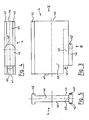
- FIG 3 of the drawing shows a single centrifugal blade 4 of the centrifugal wheel of Figures 1 and 2 in side view.
- the essential part of the centrifugal blade 4 forms the flat blade body 40
- the lower Part of the centrifugal blade 4 forms the foot part 42 with its radially outward, i. in Figure 3 to the right pointing rounding 42 '.
- the by a dashed line limited area 43 of the spinner blade 4 is the one Area in the assembled state of Impeller in the slot 34 of the cover plate 3 to lie comes. Radially inside, i. in Figure 3 left, is This region 43 is also stirred with a rounding 43 '.
- a corresponding rounding 34 ' also have the associated slots 34 in the cover plate 3rd
- the skimmer blade 4 is through the reinforcement web 45 limited, the mechanical strength the centrifugal blade 4 effectively increased.
- Right in FIG. 3 shows the radially outer edge 46 of the centrifugal blade 4, accordingly, on the left in FIG radially inner edge 41 of the centrifugal blade 4.
- the bottom view of the centrifugal blade 4 according to FIG. 4 shows the contour of the foot part 42 with the radially outer, i.e. in Figure 4 right rounding 42 '. there is particularly clear that the foot 42 as broadening opposite the narrower blade body 40 the centrifugal blade 4 is formed.
- FIG. 5 of the drawing finally shows the centrifugal blade 4 in a front view with a viewing direction in the radial direction from outside to inside according to the arrow V in Figure 3.
- the viewer's gaze falls on the radially outer edge 46 of the centrifugal blade 4.
- the foot part 42 At the bottom is in Figure 5, the foot part 42 in the form of broadening recognizable with respect to the blade body 40; there is the rounding 42 'of the foot 42 the viewer facing.
- the centrifugal blade 4 is the rounding 43 'of the area 43.
- FIG. 5 is finally back the cross-sectionally T-shaped reinforcing web 45 of Scooter 4 visible.
Landscapes
- Engineering & Computer Science (AREA)
- Mechanical Engineering (AREA)
- Structures Of Non-Positive Displacement Pumps (AREA)
- Centrifugal Separators (AREA)
Claims (14)
- Roue centrifuge (1) pour un appareil de sablage pour le traitement de surfaces de pièces à travailler, la roue centrifuge (1) comportant un disque de base (2) pouvant être assemblé à une bride d'un arbre primaire et plusieurs palettes de projection (4) assemblées de manière détachable au disque de base (2), le disque de base (2) comportant, par palette de projection (4), une rainure de logement (24), chaque palette de projection (4) comportant une partie (42) élargie servant de pied et rentrant dans la rainure de logement (24) et des moyens de blocage étant prévus pour fixer réciproquement, de manière détachable, le disque de base (2) et les palettes de projection (4), un disque de recouvrement (3) additionnel étant prévu, lequel peut être assemblé de manière détachable au disque de base (2) avec serrage des parties (42) servant de pied,
caractériséeen ce que les rainures de logement (24) accueillant respectivement la partie (42) de l'une des palettes de projection (4) servant de pied se terminent, dans le disque de base (2), vues dans le sens radial de celui-ci, avant le pourtour extérieur (26) de celui-ci,en ce que le disque de recouvrement (3) comporte des fentes (34) parallèles aux rainures de logement (24) du disque de base (2) et ouvertes vers l'extérieur dans le sens radial eten ce que la larguer des fentes (34) est dimensionnée de manière telle que respectivement une des palettes de projection (4), avec sa partie (43) non élargie voisine de la partie (42) servant de pied, rentre dans la fente (34). - Roue centrifuge selon la revendication 1, caractérisée en ce que, vue en coupe, la partie (42) de chaque palette de projection (4), servant de pied, est en forme de T et en ce que, vue en coupe, la rainure de logement (24) accueillant la partie (42) servant de pied est respectivement rectangulaire.
- Roue centrifuge selon la revendication 1 ou 2, caractérisée en ce que les parties (42) des palettes de projection (4), servant de pied, et les rainures de logement (24) du disque de base (2) sont réalisées, respectivement en leur extrémité radialement extérieure, avec des arrondis (42', 24') semi-circulaires adaptés l'un à l'autre.
- Roue centrifuge selon l'une des revendications précédentes, caractérisée en ce que les palettes de projection (4) font saillie radialement vers l'extérieur par rapport au disque de base (2) et au disque de recouvrement (3).
- Roue centrifuge selon l'une des revendications précédentes, caractérisée en ce que le disque de base (2) comporte, radialement côté intérieur des palettes de projection (4), un creux (23) concentrique sur sa face tournée vers le disque de recouvrement (3) et en ce que le disque de recouvrement (3) comporte, sur sa face tournée vers le disque de base (2), une saillie (33) concentrique circulaire rentrant dans le creux (23).
- Roue centrifuge selon la revendication 5, caractérisée en ce que la profondeur du creux (23) est identique à la profondeur des rainures de logement (24).
- Roue centrifuge selon l'une des revendications précédentes, caractérisée en ce que sont aménagés, dans la partie centrale du disque de base (2), radialement côté intérieur des palettes de projection (4), plusieurs premiers perçages (21) répartis dans le sens du pourtour, par lesquels il est possible de faire passer des vis pour assembler le disque de base (2) à la bride de l'arbre primaire.
- Roue centrifuge selon la revendication 7, caractérisée en ce que sont aménagés, dans la partie centrale du disque de base (2), radialement côté intérieur des palettes de projection (4), plusieurs deuxièmes perçages (22) répartis dans le sens du pourtour et situés entre les premiers perçages (21) et en ce que sont aménagés, dans le disque de recouvrement (3), des troisièmes perçages (32) qui se recouvrent avec les deuxièmes perçages (22) du disque de base (2), des vis, servant à caler le disque de recouvrement (3) contre le disque de base (2), pouvant traverser les couples de perçages constitués d'un deuxième et d'un troisième perçages (22, 23).
- Roue centrifuge selon l'une des revendications précédentes, caractérisée en ce que les palettes de projection (4), en leur extrémité radialement intérieure, du moins dans la partie (43) se trouvant dans la fente (34), et les fentes (34) du disque de recouvrement (3), en leur extrémité radialement intérieure, sont réalisées avec des arrondis (34', 43') semi-circulaires adaptés l'un à l'autre.
- Roue centrifuge selon l'une des revendications précédentes, caractérisée en ce que le disque de recouvrement (3) fait saillie radialement extérieurement par rapport au disque de base (2) et en ce que le disque de recouvrement (3) comporte, sur son pourtour extérieur (36), un pliage (35) qui entoure extérieurement le disque de base (2).
- Roue centrifuge selon l'une des revendications précédentes, caractérisée en ce que, vues dans le sens radial, les palettes de projection (4) sont rectilignes.
- Roue centrifuge selon l'une des revendications précédentes, caractérisée en ce que les palettes de projection (4) sont réalisées avec une nervure de renforcement (45) sur leur bord libre allant dans le sens radial et éloigné de la partie (42) servant de pied.
- Roue centrifuge selon la revendication 12, caractérisée en ce que la nervure de renforcement (45) est réalisée en forme d'élargissement.
- Roue centrifuge selon la revendication 13, caractérisée en ce que, vue en coupe, la nervure de renforcement (45) est en forme de T.
Applications Claiming Priority (2)
| Application Number | Priority Date | Filing Date | Title |
|---|---|---|---|
| DE10241019 | 2002-09-05 | ||
| DE10241019A DE10241019C1 (de) | 2002-09-05 | 2002-09-05 | Schleuderrad für eine Strahleinrichtung |
Publications (3)
| Publication Number | Publication Date |
|---|---|
| EP1396312A1 EP1396312A1 (fr) | 2004-03-10 |
| EP1396312B1 EP1396312B1 (fr) | 2005-05-25 |
| EP1396312B9 true EP1396312B9 (fr) | 2005-09-28 |
Family
ID=7714890
Family Applications (1)
| Application Number | Title | Priority Date | Filing Date |
|---|---|---|---|
| EP03018006A Expired - Lifetime EP1396312B9 (fr) | 2002-09-05 | 2003-08-07 | Roue centrifuge pour un appareil de sablage |
Country Status (2)
| Country | Link |
|---|---|
| EP (1) | EP1396312B9 (fr) |
| DE (2) | DE10241019C1 (fr) |
Family Cites Families (3)
| Publication number | Priority date | Publication date | Assignee | Title |
|---|---|---|---|---|
| DE2161888A1 (de) * | 1971-12-14 | 1973-06-20 | Rudolf Matzke | Befestigung der wurfschaufeln an strahlmittelschleuderscheiben |
| EP0688633A1 (fr) * | 1994-06-23 | 1995-12-27 | Speedlock Shotblast Systems Cc | Roue de grenaillage |
| US5888125A (en) * | 1997-11-06 | 1999-03-30 | B&U Corporation | Abrasive blast wheel with improved serviceability |
-
2002
- 2002-09-05 DE DE10241019A patent/DE10241019C1/de not_active Expired - Fee Related
-
2003
- 2003-08-07 DE DE50300573T patent/DE50300573D1/de not_active Expired - Lifetime
- 2003-08-07 EP EP03018006A patent/EP1396312B9/fr not_active Expired - Lifetime
Also Published As
| Publication number | Publication date |
|---|---|
| EP1396312A1 (fr) | 2004-03-10 |
| DE10241019C1 (de) | 2003-07-10 |
| EP1396312B1 (fr) | 2005-05-25 |
| DE50300573D1 (de) | 2005-06-30 |
Similar Documents
| Publication | Publication Date | Title |
|---|---|---|
| DE60116460T2 (de) | Schloss zur Sicherung von Laufschaufeln | |
| DE60202738T2 (de) | Vorrichtung zur Sicherung von Laufschaufeln in einer Nut einer Rotorscheibe | |
| DE2907712A1 (de) | Einrichtung bei mahlgliedern fuer mahlapparate fuer faseriges, vorzugsweise pflanzliches ausgangsgut | |
| EP1178232B1 (fr) | Elément entraineur à bride pour joint de cardan et arbre articulé | |
| EP3129600B1 (fr) | Assemblage de disque de roue | |
| EP0318669B1 (fr) | Accouplement à rondelles élastiques | |
| EP3061916A1 (fr) | Agencement de disque de rotor et procédé de montage d'un agencement de disque de rotor | |
| DE2707842B2 (de) | Raspelwerkzeug für eine Schäl- und Raspelvorrichtung zum Abtragen von Reifenlaufflächen | |
| EP1741515B1 (fr) | Outil | |
| EP3475580A1 (fr) | Disque de roue de ventilateur et roue de ventilateur | |
| DE2422639C2 (de) | Elastische Kupplung | |
| DE60016048T2 (de) | Laufrad für axialventilator und schaufel-nabe verbindungsverfahren für einen solchen ventilator | |
| EP1396312B9 (fr) | Roue centrifuge pour un appareil de sablage | |
| EP3129599B1 (fr) | Assemblage de disque de roue | |
| DE202012101196U1 (de) | Nabe für radiale Einspeichung und einen Radsatz mit derselben | |
| EP1036877B1 (fr) | Rotor avec protecteur anti-usure pour un pulpeur | |
| EP1930122B1 (fr) | Dispositif à jet avec roue centrifugue | |
| DE102010010120B4 (de) | Schleuderrad | |
| DE202019102438U1 (de) | Fräsanordnung für eine Schlitzwandfräse | |
| EP1300594A1 (fr) | Pompe centrifuge pour des eaux usées | |
| EP1455096A2 (fr) | Fixation par une sorte d'effet spirale entre cloisons et/ou étagères de meubles | |
| DE19619317C2 (de) | Laufrad für eine Freistrahltubine | |
| DE69824340T2 (de) | Fräswalze für Fräsmaschinen | |
| EP3231674A1 (fr) | Rouleau de lavage, de nettoyage et/ou de sechage | |
| WO2017032588A1 (fr) | Dispositif d'enlèvement de matériau de construction |
Legal Events
| Date | Code | Title | Description |
|---|---|---|---|
| PUAI | Public reference made under article 153(3) epc to a published international application that has entered the european phase |
Free format text: ORIGINAL CODE: 0009012 |
|
| AK | Designated contracting states |
Kind code of ref document: A1 Designated state(s): AT BE BG CH CY CZ DE DK EE ES FI FR GB GR HU IE IT LI LU MC NL PT RO SE SI SK TR |
|
| AX | Request for extension of the european patent |
Extension state: AL LT LV MK |
|
| 17P | Request for examination filed |
Effective date: 20040814 |
|
| AKX | Designation fees paid |
Designated state(s): BE DE FR GB IT NL |
|
| GRAP | Despatch of communication of intention to grant a patent |
Free format text: ORIGINAL CODE: EPIDOSNIGR1 |
|
| GRAS | Grant fee paid |
Free format text: ORIGINAL CODE: EPIDOSNIGR3 |
|
| GRAA | (expected) grant |
Free format text: ORIGINAL CODE: 0009210 |
|
| AK | Designated contracting states |
Kind code of ref document: B1 Designated state(s): BE DE FR GB IT NL |
|
| REG | Reference to a national code |
Ref country code: GB Ref legal event code: FG4D Free format text: NOT ENGLISH |
|
| REG | Reference to a national code |
Ref country code: IE Ref legal event code: FG4D Free format text: LANGUAGE OF EP DOCUMENT: GERMAN |
|
| REF | Corresponds to: |
Ref document number: 50300573 Country of ref document: DE Date of ref document: 20050630 Kind code of ref document: P |
|
| PG25 | Lapsed in a contracting state [announced via postgrant information from national office to epo] |
Ref country code: BE Free format text: LAPSE BECAUSE OF NON-PAYMENT OF DUE FEES Effective date: 20050831 |
|
| GBT | Gb: translation of ep patent filed (gb section 77(6)(a)/1977) |
Effective date: 20050902 |
|
| PLBE | No opposition filed within time limit |
Free format text: ORIGINAL CODE: 0009261 |
|
| STAA | Information on the status of an ep patent application or granted ep patent |
Free format text: STATUS: NO OPPOSITION FILED WITHIN TIME LIMIT |
|
| ET | Fr: translation filed | ||
| 26N | No opposition filed |
Effective date: 20060228 |
|
| BERE | Be: lapsed |
Owner name: SCHLICK, JENNIFER Effective date: 20050831 |
|
| PGFP | Annual fee paid to national office [announced via postgrant information from national office to epo] |
Ref country code: NL Payment date: 20130810 Year of fee payment: 11 |
|
| PGFP | Annual fee paid to national office [announced via postgrant information from national office to epo] |
Ref country code: FR Payment date: 20130808 Year of fee payment: 11 Ref country code: GB Payment date: 20130807 Year of fee payment: 11 |
|
| PGFP | Annual fee paid to national office [announced via postgrant information from national office to epo] |
Ref country code: IT Payment date: 20130807 Year of fee payment: 11 |
|
| PGFP | Annual fee paid to national office [announced via postgrant information from national office to epo] |
Ref country code: DE Payment date: 20131014 Year of fee payment: 11 |
|
| REG | Reference to a national code |
Ref country code: DE Ref legal event code: R119 Ref document number: 50300573 Country of ref document: DE |
|
| REG | Reference to a national code |
Ref country code: NL Ref legal event code: V1 Effective date: 20150301 |
|
| GBPC | Gb: european patent ceased through non-payment of renewal fee |
Effective date: 20140807 |
|
| PG25 | Lapsed in a contracting state [announced via postgrant information from national office to epo] |
Ref country code: NL Free format text: LAPSE BECAUSE OF NON-PAYMENT OF DUE FEES Effective date: 20150301 Ref country code: IT Free format text: LAPSE BECAUSE OF NON-PAYMENT OF DUE FEES Effective date: 20140807 |
|
| REG | Reference to a national code |
Ref country code: FR Ref legal event code: ST Effective date: 20150430 |
|
| REG | Reference to a national code |
Ref country code: DE Ref legal event code: R119 Ref document number: 50300573 Country of ref document: DE Effective date: 20150303 |
|
| PG25 | Lapsed in a contracting state [announced via postgrant information from national office to epo] |
Ref country code: DE Free format text: LAPSE BECAUSE OF NON-PAYMENT OF DUE FEES Effective date: 20150303 Ref country code: GB Free format text: LAPSE BECAUSE OF NON-PAYMENT OF DUE FEES Effective date: 20140807 |
|
| PG25 | Lapsed in a contracting state [announced via postgrant information from national office to epo] |
Ref country code: FR Free format text: LAPSE BECAUSE OF NON-PAYMENT OF DUE FEES Effective date: 20140901 |