EP1396335B1 - Verschlussvorrichtung für einen Druckbehälter und Behälter mit einer solchen Vorrichtung - Google Patents
Verschlussvorrichtung für einen Druckbehälter und Behälter mit einer solchen Vorrichtung Download PDFInfo
- Publication number
- EP1396335B1 EP1396335B1 EP03360101A EP03360101A EP1396335B1 EP 1396335 B1 EP1396335 B1 EP 1396335B1 EP 03360101 A EP03360101 A EP 03360101A EP 03360101 A EP03360101 A EP 03360101A EP 1396335 B1 EP1396335 B1 EP 1396335B1
- Authority
- EP
- European Patent Office
- Prior art keywords
- plate
- closing device
- profiled
- opening
- edges
- Prior art date
- Legal status (The legal status is an assumption and is not a legal conclusion. Google has not performed a legal analysis and makes no representation as to the accuracy of the status listed.)
- Expired - Lifetime
Links
Images




Classifications
-
- F—MECHANICAL ENGINEERING; LIGHTING; HEATING; WEAPONS; BLASTING
- F16—ENGINEERING ELEMENTS AND UNITS; GENERAL MEASURES FOR PRODUCING AND MAINTAINING EFFECTIVE FUNCTIONING OF MACHINES OR INSTALLATIONS; THERMAL INSULATION IN GENERAL
- F16J—PISTONS; CYLINDERS; SEALINGS
- F16J13/00—Covers or similar closure members for pressure vessels in general
- F16J13/22—Covers or similar closure members for pressure vessels in general with movement parallel to the plane of the opening
-
- B—PERFORMING OPERATIONS; TRANSPORTING
- B30—PRESSES
- B30B—PRESSES IN GENERAL
- B30B9/00—Presses specially adapted for particular purposes
- B30B9/02—Presses specially adapted for particular purposes for squeezing-out liquid from liquid-containing material, e.g. juice from fruits, oil from oil-containing material
- B30B9/22—Presses specially adapted for particular purposes for squeezing-out liquid from liquid-containing material, e.g. juice from fruits, oil from oil-containing material using a flexible member, e.g. diaphragm, urged by fluid pressure
-
- B—PERFORMING OPERATIONS; TRANSPORTING
- B30—PRESSES
- B30B—PRESSES IN GENERAL
- B30B9/00—Presses specially adapted for particular purposes
- B30B9/02—Presses specially adapted for particular purposes for squeezing-out liquid from liquid-containing material, e.g. juice from fruits, oil from oil-containing material
- B30B9/26—Permeable casings or strainers
-
- B—PERFORMING OPERATIONS; TRANSPORTING
- B65—CONVEYING; PACKING; STORING; HANDLING THIN OR FILAMENTARY MATERIAL
- B65D—CONTAINERS FOR STORAGE OR TRANSPORT OF ARTICLES OR MATERIALS, e.g. BAGS, BARRELS, BOTTLES, BOXES, CANS, CARTONS, CRATES, DRUMS, JARS, TANKS, HOPPERS, FORWARDING CONTAINERS; ACCESSORIES, CLOSURES, OR FITTINGS THEREFOR; PACKAGING ELEMENTS; PACKAGES
- B65D90/00—Component parts, details or accessories for large containers
- B65D90/54—Gates or closures
- B65D90/58—Gates or closures having closure members sliding in the plane of the opening
- B65D90/587—Gates or closures having closure members sliding in the plane of the opening having a linear motion
Definitions
- the present invention relates to the field of container closures, in particular the field of pressure vessels, and more particularly means for opening and closing pneumatic press tanks.
- the invention relates to a door device for a container and a container comprising at least one such device.
- any opening in a tank subjected to pressure causes its collapse and any deformation related to the catching of games causes a change in the initial geometry of the tank, that is to say, loss of cylindricity.
- These deformations are at the origin of stress concentrations detrimental to the holding of the tank and the fatigue resistance.
- EP-A-0 516 570 discloses a pneumatic press comprising loading and evacuation doors in the form of sliding doors associated with pairs of guide bars.
- tank door closing devices or containers
- They include slides, guide bars, reinforcements, locks that take locally or punctually the connecting forces between the door and the tank. These localized efforts are concentrated and impose sizings relatively large, so expensive.
- the purpose of the invention is in particular to overcome the aforementioned drawbacks. It also aims to provide a simple door structure and a low cost, while avoiding as much as possible the formation of a structural discontinuity and a weak point.
- the subject of the invention is a door device for a container according to claim 1.
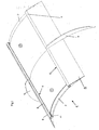
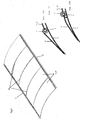
- the door device 1 is mainly constituted, on the one hand, by two profiled elements 4 and 4 'rectilinear and parallel to each other, fixed or formed on the outer face of the envelope of part. and other of the opening 3 or at the edges of the latter and, secondly, by at least one plate-shaped element 5, 5 'having a curvature close to that of the portion 2' of the shell 2 having the opening 3 and comprising two opposite edges 6 and 6 'each provided with a longitudinal profiled structure 7, parallel to each other, the cross section of which allows a hooking or retention in one of said profiled elements 4, 4 and allows a continuous sliding guided in the latter, these hollow elements 4, 4 'thus forming fastening means and slides along the entire length for said one or more element (s) 5, 5' in the form of a plate (s) and ensuring his (their) guidance between a position of f closing or closing the opening 3 and a release position or release (preferably total) of the latter.
- the invention proposes a continuous recovery efforts over the entire length of the opening, dilute and distribute these forces, which significantly reduces the size of the closing device doors and simplify structurally.
- the element or each bent element in the form of a plate 5, 5 ' is at least slightly deformable under pressure and may have at least two states corresponding to two different radii of curvature, the largest of two radii of curvature allowing a displacement in translation of the element 5, 5 'concerned and the smaller of the two radii of curvature ensuring blocking in position of said element 5, 5' concerned, the smallest of the two radii of curvature being at least slightly greater than the radius of curvature of the part 2 'of the envelope comprising the opening 3.
- the element or each plate-shaped element 5, 5 ' is mounted without play and under tension in or on the profiled elements 4 and 4 'forming slides, so that a deformation of this element 5, 5', resulting in an enlargement of its radius of curvature, is necessary to allow its displacement by sliding, said element 5, 5 'Not substantially deformed when pressurizing the container.
- the element or each plate-shaped element 5, 5 ' is mounted with clearance and being free to slide in the profiled elements 4, 4' forming slides, pressurizing the container causing a deformation of said element (s) 5, 5 'with a decrease in its radius of curvature and translation locking relative to said profiled elements 4 and 4'.
- the mounting set of the element (s) 5, 5 'forming the door corresponds to the clearance required for its operation (sliding), and it is during the pressurization that the games will be caught by the change of curvature of the door (elements 5, 5 ').
- the radius of curvature of the door at rest (with play) is greater than that of the door in the extended position, that is to say door in contact with the slide and games removed.
- it is the pressure exerted in the container that modifies the radius of curvature of the door.
- the final result is the same as in the first case mentioned above, namely that the radius of curvature of the door is always greater than that of the tank.
- connections between profiled longitudinal structure 7 and profiled element 4, 4 'respectively are configured in such a way that the resulting recesses between the edges of the opening 3 and the edges 6, 6 'of the plate-shaped element or members 5, 5' facing each other have a small height.
- the proximity of the door and container skins attenuates the discontinuity and the level of the corresponding stresses and deformations. It is the same for the position of the points of recovery efforts. In fact, the closer the geometry of the door is to the geometry of the part of the container that receives it, the lower the stresses and deformations will be.
- each sliding connection [profiled structure 7 / profiled element 4, 4 '] consists of a solid profile type connection. or wrapped sliding in a hollow or enveloping section provided with a longitudinal slot 4 ".
- the solid profiles formed integrally with the plate-shaped element or the envelope or welded to one of these (depending on the variant chosen), are in intimate surface contact with longitudinal portions 10, 10 'of the inner faces of the walls of the hollow sections extending on either side of their respective longitudinal slots 4 ", when the plate-shaped element 5, 5' concerned has the smallest radius of curvature.
- the surface contact areas will have shapes that depend on those of the hollow sections and the solid sections or thickenings in contact, that is to say for example flat ( Figures 6 and 7) or partially circular cylindrical ( Figures 3 to 5 and 12).
- the cylindricity and concentricity of the profiles in contact allows adjustment, during pressurization, of the door relative to the tank. This system allows slight rotations of the door on the container or tank to work membrane.
- the openings of the slots 4 "of the hollow profiles are substantially directed towards each other or one opposite the other in planes parallel to the planes tangent to the casing 2 at the attachment points of said profiles 4 , 4 '.
- the displacement of the element or elements 5, 5 ' can thus be achieved only after detachment of the surface areas in contact with the solid sections or thickenings of the inner face portions 10 and 10' by modifying the radius of curvature of the element or elements 5 , 5 '.
- This modification may possibly be carried out by an independent external means, by modifying the internal pressure of the container or by means reported by the door device 1.
- the profiled elements 4 and 4 ' can consist of hollow sections each having a longitudinal slot-shaped opening 4 "and can be attached directly to the outer face of the envelope 2 of the container, being fixed for example by welding, and the parallel profiled structures 7 may consist of thickened edges 6, 6 'of each plate-shaped member 5 ( Figures 1, 4, 5, 6, 7 and 12A).
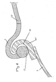
- the profiled elements 4, 4 'and the profiled structures 7 may have hook-shaped sections in cross-section, suitable for coming engaged one into the other, one of the hooks defining a groove 16 which receives the end of the other hook, optionally provided with a thickening 17.
- each profiled element 4, 4' can be connected to the envelope 2 by an element of longitudinal connection 8, such as for example an elongated strip or plate, and, where appropriate, by at least one force-recovery part 9, extending in a plane substantially perpendicular to the longitudinal direction of the profile element considered 4, 4 'and connected to the casing 2 on part of its periphery.
- an element of longitudinal connection 8 such as for example an elongated strip or plate
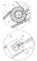
- the or each deformation device 11 comprises a support member 12 movable perpendicular to a plane tangent to the bent element 5, 5 'in the form of a plate concerned and mounted in a support structure 13 and guide means applied against said plate-shaped element 5, 5 'by symmetrical force-pickup elements 13, fixed on the element concerned 5, 5' close to its parallel opposite lateral edges 6 and 6 ', support member 12 being integral with an actuating member 12 'also allowing the sliding movement of the element 5, 5' concerned.
- the operating member 12 ' may for example consist of a rotary handle, the support member 12 being in the form of a threaded rod mounted in a threaded bushing forming part of the supporting and guiding structure 13.
- the container has a cylindrical structure with a circular section, its envelope 2 and the curved element (s) 5, 5 'in the form of a plate are made of sheet metal, preferably made of stainless steel sheet and opening 3 advantageously has a substantially rectangular shape.
- the shutter member of the opening 3 (the door panel) may also be declined in several versions.
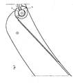
- the door device 1 may comprise a single element 5 in the form of a plate made in one piece.
- the door device 1 may comprise a single plate-shaped element 5 consisting of several adjacent sheet metal parts interconnected by flexible links 14, preferably sealed, for example under forming portions of strips of a flexible synthetic material. These flexible links make it possible to catch up with construction and assembly games.
- the door device 1 may comprise two elements 5 and 5 'in the form of independent curved plates, the mutually adjacent edges in the closed position of the opening 3 optionally comprise sealing devices, if necessary mutually cooperating.
- the invention also relates to a container, in particular a pneumatic press drum, characterized in that it comprises a door device 1 as described above.
- the face of the edges 6, 6' of the plate-shaped element (s) 5 5 'located opposite the casing portion 2' may be provided with a seal 15, preferably inflatable, extending all around the element 5, 5 'concerned.
- the envelope portion 2 'having said opening 3 is provided with a seal, preferably inflatable, extending around said opening 3.
- the opening 3 can be provided with a central cross-member 18, for example with a T-section, providing support surfaces 19 for the devices. adjacent in the closed position of the elements 5 and 5 ', for example in the form of inflatable seal portion 15 ( Figures 11A and 11B).
Landscapes
- Engineering & Computer Science (AREA)
- Mechanical Engineering (AREA)
- General Engineering & Computer Science (AREA)
- Physics & Mathematics (AREA)
- Fluid Mechanics (AREA)
- Pressure Vessels And Lids Thereof (AREA)
- Wing Frames And Configurations (AREA)
Claims (20)
- Verschlussvorrichtung für vorzugsweise zylinderförmige Behälter, umfassend mindestens einen Mantelteil mit einem gekrümmten bzw. gebogenen Querschnitt und eine in diesem Teil eingebrachte, durch die Verschlussvorrichtung zu verschließende Öffnung, wobei im Wesentlichen diese Vorrichtung (1) einerseits aus zwei geradlinigen und parallel zueinander verlaufenden Profilelementen (4 und 4') besteht, die zu beiden Seiten der Öffnung (3) bzw. im Bereich der Ränder derselben an der Außenseite des Mantels befestigt bzw. ausgebildet sind, und andererseits aus mindestens einem als Platte (5, 5') ausgebildeten Element, das eine Krümmung zeigt, die der des Teils (2') des Mantels (2), der die Öffnung (3) aufweist, nahe kommt, und das zwei einander gegenüberliegende Ränder (6 und 6') umfasst, die jeweils mit einer längslaufenden Profilstruktur (7) versehen sind, über deren Querschnitt sie in einen der Profilelemente (4, 4') eingehängt bzw. gehalten werden können und darin kontinuierlich verschiebbar sind, wobei diese Profilelemente (4, 4') auf diese Weise auf der gesamten Länge Verbindungsmittel und Gleitschienen für das bzw. die plattenförmigen Elemente (5, 5') bilden und dessen bzw. deren Führung zwischen einer die Öffnung (3) schließenden Stellung und einer diese Öffnung öffnenden bzw. freilegenden Stellung gewährleisten, wobei diese Verschlussvorrichtung (1) dadurch gekennzeichnet ist, dass das gebogene, als Platte (5, 5') ausgebildete Element unter Druck mindestens leicht verformbar ist und mindestens zwei, zwei unterschiedlichen Biegeradien entsprechende Zustände aufweisen kann, wobei der größere der beiden Biegeradien eine Verschiebung des betreffenden Elements (5, 5') zulässt und der kleinere der beiden Biegeradien eine Lagefixierung des betreffenden Elements (5, 5') gewährleistet, wobei der kleinere der beiden Biegeradien mindestens leicht größer ist als der Biegeradius des Teils (2') des Mantels, der die Öffnung (3) aufweist.
- Verschlussvorrichtung nach Anspruch 1, dadurch gekennzeichnet, dass das Element bzw. jedes Element, das als Platte (5, 5') ausgebildet ist, spielfrei und unter Spannung in bzw. an den schienenförmigen Profilelementen (4 und 4') derart montiert ist, dass eine eine Vergrößerung seines Biegeradius bewirkende Verformung dieses Elements (5, 5') erforderlich ist, um seine Verschiebung zu ermöglichen, wobei das Element (5, 5') bei der Druckbeaufschlagung des Behälters im Wesentlichen nicht verformt wird.
- Verschlussvorrichtung nach Anspruch 1, dadurch gekennzeichnet, dass das Element bzw. jedes Element, das als Platte (5, 5') ausgebildet ist, mit Spiel und frei verschiebbar in den schienenförmigen Profilelementen (4, 4') montiert ist, wobei die Druckbeaufschlagung des Behälters eine Verformung des bzw. der Elemente (5, 5') bewirkt, bei welcher dessen bzw. deren Biegeradius verringert wird und dessen bzw. deren Verschiebung relativ zu den Profilelementen (4 und 4') blockiert wird.
- Verschlussvorrichtung nach einem der Ansprüche 1 bis 3, dadurch gekennzeichnet, dass die Verbindungen zwischen der längslaufenden Profilstruktur (7) und dem jeweiligen Profilelement (4, 4') derart ausgestaltet sind, dass die Absätze, die zwischen den Rändern der Öffnung (3) und den Rändern (6, 6') des bzw. der als Platte (5, 5') ausgebildeten Elemente, welche einander gegenüberliegen, entstehen, eine geringe Höhe aufweisen.
- Verschlussvorrichtung nach einem der Ansprüche 1 bis 4, dadurch gekennzeichnet, dass jede verschiebliche Verbindung [Profilstruktur (7) / Profilelement (4, 4')] aus einer Verbindung des Typs Massivprofil bzw. ummanteltes Profil besteht, welches in einem mit einem Längsschlitz (4") versehenen Hohlprofil bzw. ummantelnden Profil verschieblich gelagert ist.
- Verschlussvorrichtung nach Anspruch 5, dadurch gekennzeichnet, dass die Massivprofile, die einstückig mit dem plattenförmigen Element bzw. mit dem Mantel ausgebildet oder daran angeschweißt sind, in engem Flächenkontakt mit längslaufenden Abschnitten (10, 10') der Innenseiten der Hohlprofilwände sind, welche sich beiderseits ihrer jeweiligen Längsschlitze (4") erstrecken, wenn das betreffende als Platte (5, 5') ausgebildete Element seinen kleinsten Biegeradius aufweist.
- Verschlussvorrichtung nach Anspruch 5 oder 6, dadurch gekennzeichnet, dass die Profilelemente (4 bzw. 4') aus Hohlprofilen bestehen, welche jeweils eine als Schlitz (4") ausgebildete längslaufende Öffnung aufweisen, und direkt an der Außenseite des Mantels (2) des Behälters angesetzt sind, an der sie beispielsweise durch Schweißen befestigt sind, und dass die parallelen Profilstrukturen (7) aus Verdickungen der Ränder (6, 6') eines jeden plattenförmigen Elements (5) bestehen.
- Verschlussvorrichtung nach Anspruch 5 oder 6, dadurch gekennzeichnet, dass die Profilelemente (4, 4') aus Verdickungen bzw. Massivprofilen bestehen, die im Bereich von einander gegenüberliegenden Rändern der Öffnung (3) angesetzt bzw. ausgebildet sind, und dass die parallelen Profilstrukturen (7) aus Hohlprofilen bestehen, die jeweils eine als Schlitz (4") ausgebildete längslaufende Öffnung aufweisen und an den jeweiligen Rändern (6, 6') ausgebildet bzw. angesetzt sind.
- Verschlussvorrichtung nach einem der Ansprüche 1 bis 4, dadurch gekennzeichnet, dass die Profilelemente (4, 4') und die Profilstrukturen (7) im Querschnitt die Form von Haken aufweisen, welche ineinander in Eingriff bringbar sind, wobei einer der Haken eine Nut (16) begrenzt, die das gegebenenfalls mit einer Verdickung (17) versehene Ende des anderen Hakens aufnimmt.
- Verschlussvorrichtung nach einem der Ansprüche 1 bis 9, dadurch gekennzeichnet, dass jedes Profilelement (4, 4') über ein längslaufendes Verbindungselement (8), wie zum Beispiel ein längliches Band oder eine längliche Platte, und gegebenenfalls über mindestens ein die Kräfte aufnehmendes Teil (9) mit dem Mantel (2) verbunden ist, wobei dieses die Kräfte aufnehmende Teil sich in einer im Wesentlichen senkrecht zur Längsrichtung des in Betracht gezogenen Profilelements (4, 4') verlaufenden Ebene erstreckt, und auf einem Teil seines Umfangs mit dem Mantel (2) verbunden ist.
- Verschlussvorrichtung nach Anspruch 2 und einem der Ansprüche 4 bis 10, dadurch gekennzeichnet, dass jedes als Platte (5, 5') ausgebildete Element an seiner Außenseite eine Vorrichtung (11) trägt, mit der seine Krümmung gesteuert verformt wird und deren Wirkung auf das Element (5, 5') darin besteht, dass seine beiden parallel verlaufenden, einander gegenüberliegenden Ränder (6 und 6') sich voneinander entfernen.
- Verschlussvorrichtung nach Anspruch 11, dadurch gekennzeichnet, dass die Verformungsvorrichtung (11) ein Stützglied (12) umfasst, welches senkrecht zu einer Ebene verschiebbar ist, die das betreffende gebogene plattenförmige Element (5, 5') berührt, und in einer Stütz- und Führungsstruktur (13) montiert ist, die an dem plattenförmigen Element (5, 5') durch symmetrische Elemente (13) zur Aufnahme der Kräfte, die an dem betreffenden Element (5, 5') in der Nähe seiner seitlichen, parallelen, einander gegenüber liegenden Ränder (6 und 6') befestigt sind, in Anlage gebracht wird, wobei das Stützglied (12) einstückig mit einem Betätigungsglied (12') verbunden ist, das auch die Verschiebung des betreffenden Elements (5, 5') ermöglicht.
- Verschlussvorrichtung nach einem der Ansprüche 1 bis 12, dadurch gekennzeichnet, dass der Behälter einen zylindrischen Aufbau mit einem kreisrunden Querschnitt aufweist, dass sein Mantel (2) und der bzw. die gebogenen, plattenförmigen Elemente (5, 5') aus einem Metallblech, vorzugsweise aus Edelstahlblech, hergestellt sind, und dass die Öffnung (3) eine im Wesentlichen rechteckige Form aufweist.
- Verschlussvorrichtung nach einem der Ansprüche 1 bis 13, dadurch gekennzeichnet, dass sie ein einziges plattenförmiges Element (5) aufweist, welches einstückig ausgebildet ist.
- Verschlussvorrichtung nach einem der Ansprüche 1 bis 13, dadurch gekennzeichnet, dass sie ein einziges plattenförmiges Element (5) aufweist, welches aus mehreren aneinander angrenzenden, aus Metallblech hergestellten Teilen besteht, die durch biegsame, vorzugsweise dichte, Verbindungen (14), beispielsweise in Form von aus einem flexiblen synthetischen Werkstoff bestehenden Bandabschnitten, untereinander verbunden sind.
- Verschlussvorrichtung nach einem der Ansprüche 1 bis 13, dadurch gekennzeichnet, dass sie zwei als unabhängige gebogene Platten ausgebildete Elemente (5 und 5') aufweist, deren jeweils aneinander liegenden Ränder in der die Öffnung (3) verschließenden Stellung eventuell Dichtvorrichtungen aufweisen, welche gegebenenfalls zusammenwirken.
- Behälter, insbesondere pneumatischer Kelterbottich, dadurch gekennzeichnet, dass er eine Verschlussvorrichtung(1) nach einem der Ansprüche 1 bis 16 umfasst.
- Behälter nach Anspruch 17, dadurch gekennzeichnet, dass die Profilelemente (4, 4') mit Bezug auf die einander gegenüberliegenden Ränder des teilweise die Öffnung (3) begrenzenden Mantels (2) nach hinten versetzt sind, wobei die dem Mantelteil (2') gegenüber liegende Seite der Ränder (6, 6') des bzw. der als Platte (5, 5') ausgebildeten Elemente mit einer abdichtenden Verkleidung (15) versehen ist, die vorzugsweise aufblasbar ist und sich über den gesamten Umfang des betreffenden Elements (5, 5') erstreckt.
- Behälter nach Anspruch 17, dadurch gekennzeichnet, dass die Profilelemente (4, 4') mit Bezug auf die einander gegenüber liegenden Ränder des teilweise die Öffnung (3) begrenzenden Mantels (2) nach hinten versetzt sind, wobei der die Öffnung (3) aufweisende Mantelteil (2') mit einer vorzugsweise aufblasbaren, abdichtenden Verkleidung versehen ist, die sich um die Öffnung (3) erstreckt.
- Behälter nach Anspruch 18, dadurch gekennzeichnet, dass, wenn die Verschlussvorrichtung (1) aus zwei als Platte (5 und 5') ausgebildeten Elementen besteht, die Öffnung (3) mit einer mittig angeordneten Quertraverse (18) mit einem beispielsweise T-förmigen Querschnitt versehen ist, welche in verschlossener Stellung der Elemente (5 und 5') den aneinander grenzenden Dichtvorrichtungen Anlageflächen (19) bietet, in Form von aufblasbaren abdichtenden Verkleidungsabschnitten (15) zum Beispiel.
Applications Claiming Priority (2)
| Application Number | Priority Date | Filing Date | Title |
|---|---|---|---|
| FR0211073 | 2002-09-06 | ||
| FR0211073A FR2844256B1 (fr) | 2002-09-06 | 2002-09-06 | Dispositif de porte pour contenant sous pression et contenant comportant un tel dispositif |
Publications (2)
| Publication Number | Publication Date |
|---|---|
| EP1396335A1 EP1396335A1 (de) | 2004-03-10 |
| EP1396335B1 true EP1396335B1 (de) | 2007-05-02 |
Family
ID=31503128
Family Applications (1)
| Application Number | Title | Priority Date | Filing Date |
|---|---|---|---|
| EP03360101A Expired - Lifetime EP1396335B1 (de) | 2002-09-06 | 2003-09-04 | Verschlussvorrichtung für einen Druckbehälter und Behälter mit einer solchen Vorrichtung |
Country Status (9)
| Country | Link |
|---|---|
| US (1) | US20040045968A1 (de) |
| EP (1) | EP1396335B1 (de) |
| AR (1) | AR041108A1 (de) |
| AT (1) | ATE361191T1 (de) |
| AU (1) | AU2003243937A1 (de) |
| DE (1) | DE60313547D1 (de) |
| ES (1) | ES2286397T3 (de) |
| FR (1) | FR2844256B1 (de) |
| ZA (1) | ZA200306911B (de) |
Cited By (1)
| Publication number | Priority date | Publication date | Assignee | Title |
|---|---|---|---|---|
| US12557832B2 (en) | 2019-09-19 | 2026-02-24 | Cnh Industrial America Llc | Destemmer for a fruit harvester |
Families Citing this family (5)
| Publication number | Priority date | Publication date | Assignee | Title |
|---|---|---|---|---|
| EP2881186A1 (de) * | 2013-12-09 | 2015-06-10 | Linde Aktiengesellschaft | Verfahren und Vorrichtung zum Isolieren der Kälte in einer Kryoausrüstung |
| EP3850208B1 (de) | 2018-09-14 | 2023-07-19 | Volvo Truck Corporation | Luftreinigergehäuse, luftreinigergehäuseanordnung und verfahren |
| CN111380429A (zh) * | 2019-12-12 | 2020-07-07 | 梁荣 | 一种卧式防爆罐 |
| DE102021126523A1 (de) * | 2021-10-13 | 2023-04-13 | Willmes Anlagentechnik Gmbh | Vorrichtung zum auspressen von flüssigkeitshaltigem pressgut |
| FR3131507B1 (fr) * | 2022-01-03 | 2023-11-24 | Bucher Vaslin | Pressoir, de préférence pneumatique, en particulier pour séparer les parties solide et liquide d’une matière, telle que de la vendange et son procédé de fermeture |
Family Cites Families (14)
| Publication number | Priority date | Publication date | Assignee | Title |
|---|---|---|---|---|
| DE137914C (de) * | 1901-10-08 | 1903-01-02 | Verschlufs mit keilförmigen, über einander greifenden Lappen für Oeffnungen an Behältern | |
| US1827743A (en) * | 1928-02-03 | 1931-10-20 | Hudson Motor Car Co | Metal automobile body |
| BE772258A (nl) * | 1971-09-07 | 1972-01-17 | Hooge Fm N V D | Inrichting voor het automatisch openen respektievelijk sluiten van een gebogen schuifdeur of dergelijke ten opzichte van een koncentrische opening. |
| US3874550A (en) * | 1973-06-21 | 1975-04-01 | Jerry D Gordon | Access door for cylinder |
| DE2449561C3 (de) * | 1974-10-18 | 1981-04-23 | Josef Willmes Kg, 6140 Bensheim | Dichtungsanordnung für einen gewölbten Verschluß-Deckel für Füll-bzw.Entleerungsöffnungen von Behältern |
| US4254960A (en) * | 1979-06-18 | 1981-03-10 | Parker-Hannifin Corporation | Sealing device |
| DE8211721U1 (de) * | 1982-04-23 | 1982-08-19 | Günter Fischer GmbH, 6706 Wachenheim | Presse zum auspressen von fluessigkeitshaltigen stoffen |
| DE3317127A1 (de) * | 1983-05-06 | 1984-11-08 | Howard Machinery Public Ltd. Co., Harleston, Norfolk | Verschiebedeckel fuer wein- oder obstpressen |
| DE3334140A1 (de) * | 1983-09-17 | 1985-04-04 | Howard Machinery PLC, Harleston, Norfolk | Pneumatische horizontalpresse |
| FR2676959A1 (fr) * | 1991-05-28 | 1992-12-04 | Pupi Matic Sa | Dispositif collecteur du mout issu du pressurage du raisin, adaptable sur un pressoir horizontal. |
| US5249392A (en) * | 1992-04-01 | 1993-10-05 | American Sterilizer Company | Apparatus for opening and closing a chamber door |
| US5259576A (en) * | 1992-05-18 | 1993-11-09 | Howard D U | External sliding aircraft door |
| US5520358A (en) * | 1994-08-18 | 1996-05-28 | E-Systems, Inc. | Door assembly with shear layer control aperture |
| CA2248054C (en) * | 1998-09-23 | 2005-09-06 | Robert Jacques Labelle | Port closure for a tank and method of retrofitting a tank with the same |
-
2002
- 2002-09-06 FR FR0211073A patent/FR2844256B1/fr not_active Expired - Fee Related
-
2003
- 2003-01-01 ZA ZA200306911A patent/ZA200306911B/xx unknown
- 2003-08-29 AR ARP030103153A patent/AR041108A1/es unknown
- 2003-08-29 AU AU2003243937A patent/AU2003243937A1/en not_active Abandoned
- 2003-09-03 US US10/653,071 patent/US20040045968A1/en not_active Abandoned
- 2003-09-04 AT AT03360101T patent/ATE361191T1/de not_active IP Right Cessation
- 2003-09-04 EP EP03360101A patent/EP1396335B1/de not_active Expired - Lifetime
- 2003-09-04 ES ES03360101T patent/ES2286397T3/es not_active Expired - Lifetime
- 2003-09-04 DE DE60313547T patent/DE60313547D1/de not_active Expired - Lifetime
Cited By (1)
| Publication number | Priority date | Publication date | Assignee | Title |
|---|---|---|---|---|
| US12557832B2 (en) | 2019-09-19 | 2026-02-24 | Cnh Industrial America Llc | Destemmer for a fruit harvester |
Also Published As
| Publication number | Publication date |
|---|---|
| US20040045968A1 (en) | 2004-03-11 |
| ATE361191T1 (de) | 2007-05-15 |
| FR2844256A1 (fr) | 2004-03-12 |
| AU2003243937A1 (en) | 2004-03-25 |
| AR041108A1 (es) | 2005-05-04 |
| DE60313547D1 (de) | 2007-06-14 |
| ZA200306911B (en) | 2004-03-09 |
| EP1396335A1 (de) | 2004-03-10 |
| FR2844256B1 (fr) | 2005-05-13 |
| ES2286397T3 (es) | 2007-12-01 |
Similar Documents
| Publication | Publication Date | Title |
|---|---|---|
| EP2674362B1 (de) | Bolzenschließvorrichtung | |
| CA1097385A (fr) | Plinthe automatique | |
| EP2122102B1 (de) | Vorrichtung mit flexiblem vorhang | |
| EP1310353A1 (de) | Verschlussvorrichtung für Presse sowie Verfahren zu deren Herstellung | |
| FR2857400A1 (fr) | Verrou destine a relier deux panneaux d'une structure d'aeroplane | |
| FR2518217A1 (fr) | Reservoir pour le stockage et le transport d'un liquide sous pression | |
| EP1396335B1 (de) | Verschlussvorrichtung für einen Druckbehälter und Behälter mit einer solchen Vorrichtung | |
| EP2000626B1 (de) | Montagevorrichtung für Rollladen | |
| CA2128930C (fr) | Touret pliable | |
| FR2613986A1 (fr) | Porte a rideau relevant notamment pour vehicule de transport | |
| EP1967624B1 (de) | Webblatt für eine Webmaschine, Webmaschine die ein solches Webblatt umfasst und Herstellungsverfahren eines solchen Webblattes | |
| FR2821113A1 (fr) | Attache anti-relevage pour volet roulant | |
| WO2011077033A2 (fr) | Dispositif d'obturation et ensemble correspondant | |
| FR2619292A1 (fr) | Fermoir pour bracelet | |
| EP1140535A1 (de) | Sicherheitsvorrichtung mit glasöffnung mit beweglichem verschluss | |
| EP0479663A1 (de) | Türfeststeller für Fahrzeuge | |
| WO2006051236A1 (fr) | Dispositif de fixation d'une toile tendue | |
| WO1985000328A1 (fr) | Essuie-glace comportant un axe d'articulation du balai sur le bras a verrouillage transversal | |
| CH630145A5 (fr) | Reservoir de pression. | |
| EP2020324A1 (de) | Vorrichtung zum Befestigen eines Bügels an einem Fördergefäß | |
| FR2753677A1 (fr) | Obturateur pour une ouverture traversant une paroi ayant une faible rigidite et son utilisation | |
| EP1718827B1 (de) | Antipanikstange und damit ausgerüstete tür | |
| BE1017124A6 (fr) | Dispositif a rideau flexible. | |
| FR2487422A1 (fr) | Perfectionnements aux dispositifs de verrouillage automatique de volets roulants | |
| FR2721966A1 (fr) | Dispositif d'arret de porte pour vehicule automobile |
Legal Events
| Date | Code | Title | Description |
|---|---|---|---|
| PUAI | Public reference made under article 153(3) epc to a published international application that has entered the european phase |
Free format text: ORIGINAL CODE: 0009012 |
|
| AK | Designated contracting states |
Kind code of ref document: A1 Designated state(s): AT BE BG CH CY CZ DE DK EE ES FI FR GB GR HU IE IT LI LU MC NL PT RO SE SI SK TR |
|
| AX | Request for extension of the european patent |
Extension state: AL LT LV MK |
|
| 17P | Request for examination filed |
Effective date: 20040903 |
|
| AKX | Designation fees paid |
Designated state(s): AT BE BG CH CY CZ DE DK EE ES FI FR GB GR HU IE IT LI LU MC NL PT RO SE SI SK TR |
|
| 17Q | First examination report despatched |
Effective date: 20050208 |
|
| GRAP | Despatch of communication of intention to grant a patent |
Free format text: ORIGINAL CODE: EPIDOSNIGR1 |
|
| GRAS | Grant fee paid |
Free format text: ORIGINAL CODE: EPIDOSNIGR3 |
|
| RAP1 | Party data changed (applicant data changed or rights of an application transferred) |
Owner name: BUCHER VASLIN |
|
| GRAA | (expected) grant |
Free format text: ORIGINAL CODE: 0009210 |
|
| AK | Designated contracting states |
Kind code of ref document: B1 Designated state(s): AT BE BG CH CY CZ DE DK EE ES FI FR GB GR HU IE IT LI LU MC NL PT RO SE SI SK TR |
|
| PG25 | Lapsed in a contracting state [announced via postgrant information from national office to epo] |
Ref country code: FI Free format text: LAPSE BECAUSE OF FAILURE TO SUBMIT A TRANSLATION OF THE DESCRIPTION OR TO PAY THE FEE WITHIN THE PRESCRIBED TIME-LIMIT Effective date: 20070502 |
|
| REG | Reference to a national code |
Ref country code: GB Ref legal event code: FG4D Free format text: NOT ENGLISH |
|
| REG | Reference to a national code |
Ref country code: CH Ref legal event code: EP |
|
| REG | Reference to a national code |
Ref country code: IE Ref legal event code: FG4D Free format text: LANGUAGE OF EP DOCUMENT: FRENCH |
|
| REF | Corresponds to: |
Ref document number: 60313547 Country of ref document: DE Date of ref document: 20070614 Kind code of ref document: P |
|
| PG25 | Lapsed in a contracting state [announced via postgrant information from national office to epo] |
Ref country code: SE Free format text: LAPSE BECAUSE OF FAILURE TO SUBMIT A TRANSLATION OF THE DESCRIPTION OR TO PAY THE FEE WITHIN THE PRESCRIBED TIME-LIMIT Effective date: 20070802 |
|
| NLV1 | Nl: lapsed or annulled due to failure to fulfill the requirements of art. 29p and 29m of the patents act | ||
| PG25 | Lapsed in a contracting state [announced via postgrant information from national office to epo] |
Ref country code: AT Free format text: LAPSE BECAUSE OF FAILURE TO SUBMIT A TRANSLATION OF THE DESCRIPTION OR TO PAY THE FEE WITHIN THE PRESCRIBED TIME-LIMIT Effective date: 20070502 |
|
| GBV | Gb: ep patent (uk) treated as always having been void in accordance with gb section 77(7)/1977 [no translation filed] |
Effective date: 20070502 |
|
| REG | Reference to a national code |
Ref country code: ES Ref legal event code: FG2A Ref document number: 2286397 Country of ref document: ES Kind code of ref document: T3 |
|
| REG | Reference to a national code |
Ref country code: IE Ref legal event code: FD4D |
|
| PG25 | Lapsed in a contracting state [announced via postgrant information from national office to epo] |
Ref country code: BG Free format text: LAPSE BECAUSE OF FAILURE TO SUBMIT A TRANSLATION OF THE DESCRIPTION OR TO PAY THE FEE WITHIN THE PRESCRIBED TIME-LIMIT Effective date: 20070802 Ref country code: SI Free format text: LAPSE BECAUSE OF FAILURE TO SUBMIT A TRANSLATION OF THE DESCRIPTION OR TO PAY THE FEE WITHIN THE PRESCRIBED TIME-LIMIT Effective date: 20070502 Ref country code: NL Free format text: LAPSE BECAUSE OF FAILURE TO SUBMIT A TRANSLATION OF THE DESCRIPTION OR TO PAY THE FEE WITHIN THE PRESCRIBED TIME-LIMIT Effective date: 20070502 Ref country code: PT Free format text: LAPSE BECAUSE OF FAILURE TO SUBMIT A TRANSLATION OF THE DESCRIPTION OR TO PAY THE FEE WITHIN THE PRESCRIBED TIME-LIMIT Effective date: 20071002 Ref country code: IE Free format text: LAPSE BECAUSE OF FAILURE TO SUBMIT A TRANSLATION OF THE DESCRIPTION OR TO PAY THE FEE WITHIN THE PRESCRIBED TIME-LIMIT Effective date: 20070502 Ref country code: DK Free format text: LAPSE BECAUSE OF FAILURE TO SUBMIT A TRANSLATION OF THE DESCRIPTION OR TO PAY THE FEE WITHIN THE PRESCRIBED TIME-LIMIT Effective date: 20070502 Ref country code: CZ Free format text: LAPSE BECAUSE OF FAILURE TO SUBMIT A TRANSLATION OF THE DESCRIPTION OR TO PAY THE FEE WITHIN THE PRESCRIBED TIME-LIMIT Effective date: 20070502 |
|
| PG25 | Lapsed in a contracting state [announced via postgrant information from national office to epo] |
Ref country code: SK Free format text: LAPSE BECAUSE OF FAILURE TO SUBMIT A TRANSLATION OF THE DESCRIPTION OR TO PAY THE FEE WITHIN THE PRESCRIBED TIME-LIMIT Effective date: 20070502 |
|
| PLBE | No opposition filed within time limit |
Free format text: ORIGINAL CODE: 0009261 |
|
| STAA | Information on the status of an ep patent application or granted ep patent |
Free format text: STATUS: NO OPPOSITION FILED WITHIN TIME LIMIT |
|
| BERE | Be: lapsed |
Owner name: BUCHER VASLIN Effective date: 20070930 |
|
| 26N | No opposition filed |
Effective date: 20080205 |
|
| PG25 | Lapsed in a contracting state [announced via postgrant information from national office to epo] |
Ref country code: GB Free format text: LAPSE BECAUSE OF FAILURE TO SUBMIT A TRANSLATION OF THE DESCRIPTION OR TO PAY THE FEE WITHIN THE PRESCRIBED TIME-LIMIT Effective date: 20070502 Ref country code: DE Free format text: LAPSE BECAUSE OF FAILURE TO SUBMIT A TRANSLATION OF THE DESCRIPTION OR TO PAY THE FEE WITHIN THE PRESCRIBED TIME-LIMIT Effective date: 20070803 Ref country code: GR Free format text: LAPSE BECAUSE OF FAILURE TO SUBMIT A TRANSLATION OF THE DESCRIPTION OR TO PAY THE FEE WITHIN THE PRESCRIBED TIME-LIMIT Effective date: 20070803 Ref country code: MC Free format text: LAPSE BECAUSE OF NON-PAYMENT OF DUE FEES Effective date: 20070930 |
|
| REG | Reference to a national code |
Ref country code: CH Ref legal event code: PL |
|
| PG25 | Lapsed in a contracting state [announced via postgrant information from national office to epo] |
Ref country code: RO Free format text: LAPSE BECAUSE OF FAILURE TO SUBMIT A TRANSLATION OF THE DESCRIPTION OR TO PAY THE FEE WITHIN THE PRESCRIBED TIME-LIMIT Effective date: 20070502 |
|
| PG25 | Lapsed in a contracting state [announced via postgrant information from national office to epo] |
Ref country code: LI Free format text: LAPSE BECAUSE OF NON-PAYMENT OF DUE FEES Effective date: 20070930 Ref country code: CH Free format text: LAPSE BECAUSE OF NON-PAYMENT OF DUE FEES Effective date: 20070930 |
|
| PG25 | Lapsed in a contracting state [announced via postgrant information from national office to epo] |
Ref country code: BE Free format text: LAPSE BECAUSE OF NON-PAYMENT OF DUE FEES Effective date: 20070930 |
|
| PG25 | Lapsed in a contracting state [announced via postgrant information from national office to epo] |
Ref country code: EE Free format text: LAPSE BECAUSE OF FAILURE TO SUBMIT A TRANSLATION OF THE DESCRIPTION OR TO PAY THE FEE WITHIN THE PRESCRIBED TIME-LIMIT Effective date: 20070502 |
|
| PG25 | Lapsed in a contracting state [announced via postgrant information from national office to epo] |
Ref country code: CY Free format text: LAPSE BECAUSE OF FAILURE TO SUBMIT A TRANSLATION OF THE DESCRIPTION OR TO PAY THE FEE WITHIN THE PRESCRIBED TIME-LIMIT Effective date: 20070502 |
|
| PG25 | Lapsed in a contracting state [announced via postgrant information from national office to epo] |
Ref country code: LU Free format text: LAPSE BECAUSE OF NON-PAYMENT OF DUE FEES Effective date: 20070904 |
|
| PG25 | Lapsed in a contracting state [announced via postgrant information from national office to epo] |
Ref country code: HU Free format text: LAPSE BECAUSE OF FAILURE TO SUBMIT A TRANSLATION OF THE DESCRIPTION OR TO PAY THE FEE WITHIN THE PRESCRIBED TIME-LIMIT Effective date: 20071103 Ref country code: TR Free format text: LAPSE BECAUSE OF FAILURE TO SUBMIT A TRANSLATION OF THE DESCRIPTION OR TO PAY THE FEE WITHIN THE PRESCRIBED TIME-LIMIT Effective date: 20070502 |
|
| REG | Reference to a national code |
Ref country code: FR Ref legal event code: PLFP Year of fee payment: 14 |
|
| REG | Reference to a national code |
Ref country code: FR Ref legal event code: PLFP Year of fee payment: 15 |
|
| REG | Reference to a national code |
Ref country code: FR Ref legal event code: PLFP Year of fee payment: 16 |
|
| PGFP | Annual fee paid to national office [announced via postgrant information from national office to epo] |
Ref country code: FR Payment date: 20220930 Year of fee payment: 20 |
|
| PGFP | Annual fee paid to national office [announced via postgrant information from national office to epo] |
Ref country code: IT Payment date: 20220929 Year of fee payment: 20 Ref country code: ES Payment date: 20221121 Year of fee payment: 20 |
|
| REG | Reference to a national code |
Ref country code: ES Ref legal event code: FD2A Effective date: 20230926 |
|
| PG25 | Lapsed in a contracting state [announced via postgrant information from national office to epo] |
Ref country code: ES Free format text: LAPSE BECAUSE OF EXPIRATION OF PROTECTION Effective date: 20230905 |