EP1396419A2 - Umwerfer für ein Fahrrad - Google Patents
Umwerfer für ein Fahrrad Download PDFInfo
- Publication number
- EP1396419A2 EP1396419A2 EP03020017A EP03020017A EP1396419A2 EP 1396419 A2 EP1396419 A2 EP 1396419A2 EP 03020017 A EP03020017 A EP 03020017A EP 03020017 A EP03020017 A EP 03020017A EP 1396419 A2 EP1396419 A2 EP 1396419A2
- Authority
- EP
- European Patent Office
- Prior art keywords
- base member
- derailleur
- abutment
- abutment portion
- interlock
- Prior art date
- Legal status (The legal status is an assumption and is not a legal conclusion. Google has not performed a legal analysis and makes no representation as to the accuracy of the status listed.)
- Granted
Links
Images



Classifications
-
- B—PERFORMING OPERATIONS; TRANSPORTING
- B62—LAND VEHICLES FOR TRAVELLING OTHERWISE THAN ON RAILS
- B62M—RIDER PROPULSION OF WHEELED VEHICLES OR SLEDGES; POWERED PROPULSION OF SLEDGES OR SINGLE-TRACK CYCLES; TRANSMISSIONS SPECIALLY ADAPTED FOR SUCH VEHICLES
- B62M9/00—Transmissions characterised by use of an endless chain, belt, or the like
- B62M9/04—Transmissions characterised by use of an endless chain, belt, or the like of changeable ratio
- B62M9/06—Transmissions characterised by use of an endless chain, belt, or the like of changeable ratio using a single chain, belt, or the like
- B62M9/10—Transmissions characterised by use of an endless chain, belt, or the like of changeable ratio using a single chain, belt, or the like involving different-sized wheels, e.g. rear sprocket chain wheels selectively engaged by the chain, belt, or the like
- B62M9/12—Transmissions characterised by use of an endless chain, belt, or the like of changeable ratio using a single chain, belt, or the like involving different-sized wheels, e.g. rear sprocket chain wheels selectively engaged by the chain, belt, or the like the chain, belt, or the like being laterally shiftable, e.g. using a rear derailleur
- B62M9/121—Rear derailleurs
- B62M9/124—Mechanisms for shifting laterally
- B62M9/1244—Mechanisms for shifting laterally limiting or positioning the movement
-
- B—PERFORMING OPERATIONS; TRANSPORTING
- B62—LAND VEHICLES FOR TRAVELLING OTHERWISE THAN ON RAILS
- B62M—RIDER PROPULSION OF WHEELED VEHICLES OR SLEDGES; POWERED PROPULSION OF SLEDGES OR SINGLE-TRACK CYCLES; TRANSMISSIONS SPECIALLY ADAPTED FOR SUCH VEHICLES
- B62M9/00—Transmissions characterised by use of an endless chain, belt, or the like
- B62M9/04—Transmissions characterised by use of an endless chain, belt, or the like of changeable ratio
- B62M9/06—Transmissions characterised by use of an endless chain, belt, or the like of changeable ratio using a single chain, belt, or the like
- B62M9/10—Transmissions characterised by use of an endless chain, belt, or the like of changeable ratio using a single chain, belt, or the like involving different-sized wheels, e.g. rear sprocket chain wheels selectively engaged by the chain, belt, or the like
- B62M9/12—Transmissions characterised by use of an endless chain, belt, or the like of changeable ratio using a single chain, belt, or the like involving different-sized wheels, e.g. rear sprocket chain wheels selectively engaged by the chain, belt, or the like the chain, belt, or the like being laterally shiftable, e.g. using a rear derailleur
- B62M9/121—Rear derailleurs
- B62M9/124—Mechanisms for shifting laterally
- B62M9/1242—Mechanisms for shifting laterally characterised by the linkage mechanisms
Definitions
- the present invention is directed to bicycles and, more particularly, to a bicycle derailleur with a structure that inhibits misalignment of a drive mechanism relative to first and second base members.
- Bicycles are used for general transportation as well as for sports and recreation. Such potential uses have resulted in the development of bicycles that are comfortable to ride under a variety of riding conditions and are suitable for a wide variety of riding purposes. Not surprisingly, bicycles that have some provision for the automation of various components to accommodate a particular riding environment have become very popular.
- Such transmissions may include a derailleur that is detachably secured to the rear end of the bicycle frame and is used to engage a chain with one of a plurality of sprockets that are mounted on the hub axle of the rear wheel.
- Conventional rear derailleur comprise a base member mounted on the rear end of the bicycle frame, a four-point link mechanism mounted to the base member, and a chain guide mounted to the four-point link mechanism. During operation of the rear derailleur, the four-point link mechanism moves the chain guide in the direction of the hub axle, and the chain guide switches the chain to a desired one of the plurality of sprockets.
- rear derailleur include a drive mechanism, such as a rotating motor, housed within the base member.
- the base member may comprise a plurality of members that form a housing space, and the drive mechanism may be disposed within the housing space.
- the four-point link mechanism is controlled by this drive mechanism, thus allowing the rear derailleur to be more easily operated in both automatic and manual shifting modes.
- the plurality of base members can become misaligned with each other due to impacts on the base member caused by falls as well as by vibrations and shocks caused by changes in the surface of the road. This also causes the drive mechanism to become misaligned in the housing space between the base members, thus adversely affecting the ability of the derailleur to precisely shift the chain from one sprocket to another.
- a bicycle derailleur comprises a first base member structured to be detachably mounted to a bicycle frame, wherein the first base member has a first abutment; a second base member structured to be mounted to the first base member, wherein the second base member has a second abutment that faces the first abutment of the first base member such that the first and second base members define a housing space between them; a drive mechanism at least partially disposed in the housing space; a link mechanism that moves in response to movement of the drive mechanism; a chain guide coupled to the link mechanism for moving a chain among a plurality of sprockets; and a misalignment inhibiting structure disposed between the first base member and the second base member to inhibit misalignment of the drive mechanism as a result of an external force.
- Fig. 1 is a side view of a particular embodiment of a rear derailleur 1.
- Rear derailleur 1 comprises a first base member 2 and separate second base member 3, a drive mechanism 4 disposed between the first and second base members 2 and 3, a four-point link mechanism 5 pivotably coupled to the first and second base members 2 and 3, and a chain guide 8 pivotably coupled to the four-point link mechanism 5.
- four-point link mechanism 5 comprises link shafts 22 mounted on the drive mechanism 4, first and second link members 23 and 24 pivotably mounted about the link shafts 22, a biasing member 25 that biases the first and second link members 23 and 24 in one of the pivoting directions, and a coupler 26 pivotably mounted to the other ends of the first and second link member 23 and 24.
- Biasing member 25 is mounted diagonally between the link shaft 22 at the first end of first link member 23 and the link shaft 22 at the second end of second link member 24.
- chain guide 8 comprises a pair of guide frames 28 that rotatably support a pair of guide sprockets 27 such that guide sprockets 27 are sandwiched between the pair of guide frames 28.
- Guide frames 28 are mounted to coupler 26 so that one end of each guide frame 28 pivots around an axis parallel to the hub axle 6.
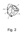
- First base member 2 is detachably mounted on the rear end of a bicycle frame 9. As shown in Fig. 3, first base member 2 forms a housing space that opens towards second base member 3, and an abutment 30a is formed on a side of first base member 2 that faces second base member 3. Threaded openings 10 are formed at an upper portion of first base member 2, and threaded openings 10a are formed at a lower portion of first base member 2, wherein the threaded openings 10 and 10a face second base member 3. A through hole 12 is formed in the top surface of first base member 2 to allow a control cable 11 to be attached to drive mechanism 4.
- Second base member 3 forms a housing space that opens towards first base member 2, and an abutment 30b is formed on a side of second base member 3 that faces first base member 2.
- Bolt openings 13 are formed at an upper portion of second base member 3, and bolt openings 13a are formed at a lower portion of second base member 3, wherein the bolt openings 13 and 13a face the threaded openings 10 and 10a, respectively, in first base member 2.
- abutments 30a and 30b contact each other when first base member 2 and second base member 3 are assembled together, and a housing space is formed on the inside of first and second base members 2 and 3.
- first misalignment-inhibiting or interlocking structure 14a is disposed between first base member 2 and second base member 3 at threaded openings 10 and bolt openings 13.
- first misalignment-inhibiting structure 14a comprises recesses 15 and tubular guides 16.
- Recesses 15 are concentrically formed in the mutually opposed faces of first and second base members 2 and 3 at threaded openings 10 and bolt holes 13.
- Tubular guides 16 pass through openings 20 in drive mechanism 4 and are disposed in recesses 15 such that the ends of tubular guides 16 contact floors 18 of recesses 15.
- Bolts 17 extend through bolt openings 13 and tubular guides 16 and screw into threaded openings 10 in first base member 2.
- first abutment 30a includes a substantially straight first abutment portion near the top of first base member 2, a substantially straight second abutment portion extending at an incline from the first abutment portion, and a substantially straight third abutment portion extending from the second abutment portion.
- the second abutment portion is inclined relative to the third abutment portion, and the first abutment portion is aligned offset substantially parallel to the third abutment portion.
- second abutment 30b includes a substantially straight first abutment portion near the top of second base member 3, a substantially straight second abutment portion extending at an incline from the first abutment portion, and a substantially straight third abutment portion extending from the second abutment portion.
- the second abutment portion is inclined relative to the third abutment portion, and the first abutment portion is aligned offset substantially parallel to the third abutment portion.
- Drive mechanism 4 is sandwiched between first base member 2 and second base member 3 and is positioned by the tubular guides 16 that extend through the openings 20 in drive mechanism 20.
- a cable attachment component 21 for the control cable 11 is provided on the side of drive mechanism 4 that faces first base member 2.
- control signals for controlling drive mechanism 4 according to changes in the riding conditions are received by drive mechanism 4 through cable 11 at cable attachment component 21.
- Drive mechanism 4 operates in response to these control signals, and four-point link mechanism 5 mounted on link shafts 22 driven by drive mechanism 4 moves accordingly.
- guide frames 28 move in the direction of the hub axle, and the chain 7 supported by guide sprockets 27 is switched to a desired one of the plurality of sprockets 50.
- first and second base members 2 and 3 can become misaligned if derailleur 1 is subjected to impact during falls or is subjected to vibrations and/or shocks resulting from changes in the road surface. This, in turn, causes misalignment of drive mechanism 4. Stress resulting from misalignment of first and second base members 2 and 3 also can be transmitted from first and second base members 2 and 3 through the attachment bolts to the drive mechanism 4. To ensure satisfactory derailleur performance in such circumstances, the stability of the drive mechanism 4 disposed between the first and second base members 2 and 3 must be maintained.
- the first misalignment-inhibiting structure 14a prevents forces applied to the first and second base members 2 and 3 from being transmitted to the drive mechanism 4 because such forces are communicated through the tubular guides 16 from one base member to the other through the floors 18 in the recesses 15.
- the forces that could potentially be transmitted through the bolts 17 to the drive mechanism 4 is absorbed and buffered by the guides 16, thus protecting the drive mechanism 4 against such external forces. This makes it possible to maintain and ensure the stability of the drive mechanism 4 disposed between the first and second base members 2 and 3.
- the second misalignment-preventing member 14b also directly transmits forces between the first and second base members 2 and 3 through junction 19 and also inhibits relative rotation between the first and second base members 2 and 3 in response to external forces on the first and second base members 2 and 3. This, too, makes it possible to maintain and ensure the stability of the drive mechanism 4 disposed between the first and second base members 2 and 3.
- first and second abutments 30a and 30b of the second misalignment inhibiting structure 14b in the above embodiment had an inclined intermediate portion, but the shape of the abutments can take many forms in order to resist external forces.
- the intermediate portions of the abutments 30a and 30b may be perpendicular to one or both of the adjacent abutment portions to form a perpendicular abutment 40.
- Such an abutment helps to inhibit misalignment caused by shear forces applied to the first and second base members 2 and 3.
- a second misalignment-inhibiting structure 14b may include an abutment 40b provided at the bottom end of a first base member 2b for contacting the entire bottom surface of a second base member 3b. In this case as well, it is possible to inhibit misalignment resulting from shear forces applied to the first and second base members 2a and 2b and to inhibit frictional forces applied to the junction 19.
- first base member 2 was directly bolted to the frame 9, but any attachment method that ensures integrity with the frame 9 may be used.
- first base member 2 can be integrated with frame 9 by means of a bracket.
Landscapes
- Engineering & Computer Science (AREA)
- Chemical & Material Sciences (AREA)
- Combustion & Propulsion (AREA)
- Transportation (AREA)
- Mechanical Engineering (AREA)
- Devices For Conveying Motion By Means Of Endless Flexible Members (AREA)
- Automatic Cycles, And Cycles In General (AREA)
- Axle Suspensions And Sidecars For Cycles (AREA)
Applications Claiming Priority (2)
| Application Number | Priority Date | Filing Date | Title |
|---|---|---|---|
| JP2002261901 | 2002-09-06 | ||
| JP2002261901A JP3645877B2 (ja) | 2002-09-06 | 2002-09-06 | 自転車用リアディレーラ |
Publications (3)
| Publication Number | Publication Date |
|---|---|
| EP1396419A2 true EP1396419A2 (de) | 2004-03-10 |
| EP1396419A3 EP1396419A3 (de) | 2006-03-08 |
| EP1396419B1 EP1396419B1 (de) | 2007-11-14 |
Family
ID=31712348
Family Applications (1)
| Application Number | Title | Priority Date | Filing Date |
|---|---|---|---|
| EP03020017A Expired - Lifetime EP1396419B1 (de) | 2002-09-06 | 2003-09-03 | Umwerfer für ein Fahrrad |
Country Status (6)
| Country | Link |
|---|---|
| US (1) | US7320655B2 (de) |
| EP (1) | EP1396419B1 (de) |
| JP (1) | JP3645877B2 (de) |
| CN (1) | CN1488548A (de) |
| DE (1) | DE60317421T2 (de) |
| TW (1) | TW200404705A (de) |
Cited By (2)
| Publication number | Priority date | Publication date | Assignee | Title |
|---|---|---|---|---|
| DE102017010348A1 (de) | 2017-11-09 | 2019-05-09 | Sram Deutschland Gmbh | Elektromechanisches Schaltwerk |
| EP4112435A3 (de) * | 2021-06-29 | 2023-03-29 | SRAM Deutschland GmbH | Modulares fahrrad-schaltwerk |
Families Citing this family (15)
| Publication number | Priority date | Publication date | Assignee | Title |
|---|---|---|---|---|
| US9033833B2 (en) | 2011-01-28 | 2015-05-19 | Paha Designs, Llc | Gear transmission and derailleur system |
| US10207772B2 (en) | 2011-01-28 | 2019-02-19 | Paha Designs, Llc | Gear transmission and derailleur system |
| US9327792B2 (en) | 2011-01-28 | 2016-05-03 | Paha Designs, Llc | Gear transmission and derailleur system |
| TWM421248U (en) * | 2011-07-01 | 2012-01-21 | Hai-Huan Jiang | Adjusting device of fixing rod installed in the hub shaft of bicycle |
| US8900078B2 (en) * | 2011-10-05 | 2014-12-02 | Shimano Inc. | Bicycle derailleur |
| US8979683B2 (en) * | 2012-01-31 | 2015-03-17 | Shimano Inc. | Bicycle electric actuator unit |
| US9394030B2 (en) | 2012-09-27 | 2016-07-19 | Sram, Llc | Rear derailleur |
| US9676444B2 (en) * | 2013-10-23 | 2017-06-13 | Sram, Llc | Electromechanical rear derailleur |
| US9656723B1 (en) * | 2015-12-14 | 2017-05-23 | Shimano Inc. | Electrical bicycle derailleur |
| IT201700018702A1 (it) * | 2017-02-20 | 2018-08-20 | Campagnolo Srl | Deragliatore elettrico posteriore di bicicletta |
| TWM562815U (zh) * | 2018-04-03 | 2018-07-01 | 彥豪金屬工業股份有限公司 | 變速器總成 |
| TWM562816U (zh) * | 2018-04-03 | 2018-07-01 | 彥豪金屬工業股份有限公司 | 變速器總成 |
| US11498643B2 (en) * | 2019-02-26 | 2022-11-15 | Shimano Inc. | Bicycle electric derailleur |
| US11981398B2 (en) * | 2020-09-11 | 2024-05-14 | Shimano Inc. | Bicycle derailleur |
| US20220297798A1 (en) * | 2021-03-16 | 2022-09-22 | Tien Hsin Industries Co., Ltd. | Electronic derailleur |
Family Cites Families (19)
| Publication number | Priority date | Publication date | Assignee | Title |
|---|---|---|---|---|
| US3919891A (en) * | 1973-10-15 | 1975-11-18 | Brian J Stuhlmuller | Electrical gear changer for chain driven vehicle |
| NL8200459A (nl) * | 1982-02-05 | 1983-09-01 | Allpac Int Bv | Optrekinrichting. |
| US4616164A (en) * | 1984-03-28 | 1986-10-07 | Eaton Corporation | Feedback servo actuator |
| GB2159001B (en) * | 1984-05-19 | 1987-11-11 | Delco Prod Overseas | Electrically-operable actuator |
| JPS63119196U (de) * | 1987-01-28 | 1988-08-02 | ||
| IT1252263B (it) * | 1991-11-18 | 1995-06-08 | Catene Calibrate Regina | Cambio elettromeccanico per bicicletta |
| DE4340471C1 (de) | 1993-11-27 | 1995-02-02 | Fichtel & Sachs Ag | Kettenschaltung für Fahrräder |
| US5599244A (en) * | 1995-08-14 | 1997-02-04 | Ethington; Russell A. | Automatic transmission shifter for velocipedes |
| JP3412360B2 (ja) * | 1995-10-06 | 2003-06-03 | アイシン・エィ・ダブリュ株式会社 | 自動変速機 |
| US5737968A (en) * | 1996-05-07 | 1998-04-14 | Hardey; Donald H. | Integrated gear motor and method of assembly |
| JPH10181675A (ja) * | 1996-12-20 | 1998-07-07 | Jeco Co Ltd | 自動変速装置 |
| US6028384A (en) * | 1998-11-17 | 2000-02-22 | Cei | Actuator |
| US6162140A (en) * | 1998-12-18 | 2000-12-19 | Shimano, Inc. | Motor driven derailleur |
| US6118197A (en) * | 1999-02-26 | 2000-09-12 | General Electric Company | Apparatus and methods for protecting motor from air borne contaminants |
| JP2000266177A (ja) * | 1999-03-16 | 2000-09-26 | Bridgestone Cycle Co | 自動変速装置における低電圧検出装置 |
| US6054785A (en) * | 1999-05-21 | 2000-04-25 | Molon Motor & Coil Corporation | Compact miniature motor |
| USD451072S1 (en) * | 1999-10-29 | 2001-11-27 | Molon Motor & Coil Corporation | Compact gear motor box |
| US6293882B1 (en) * | 1999-12-10 | 2001-09-25 | Shimano, Inc. | Operating force compensating apparatus for a bicycle transmission |
| DE10125582A1 (de) * | 2001-05-25 | 2002-12-05 | Webasto Vehicle Sys Int Gmbh | Antriebsvorrichtung |
-
2002
- 2002-09-06 JP JP2002261901A patent/JP3645877B2/ja not_active Expired - Fee Related
-
2003
- 2003-08-18 TW TW092122647A patent/TW200404705A/zh unknown
- 2003-09-03 EP EP03020017A patent/EP1396419B1/de not_active Expired - Lifetime
- 2003-09-03 DE DE60317421T patent/DE60317421T2/de not_active Expired - Lifetime
- 2003-09-03 US US10/605,036 patent/US7320655B2/en not_active Expired - Fee Related
- 2003-09-05 CN CNA03155461XA patent/CN1488548A/zh active Pending
Cited By (7)
| Publication number | Priority date | Publication date | Assignee | Title |
|---|---|---|---|---|
| DE102017010348A1 (de) | 2017-11-09 | 2019-05-09 | Sram Deutschland Gmbh | Elektromechanisches Schaltwerk |
| EP3483053A1 (de) | 2017-11-09 | 2019-05-15 | SRAM Deutschland GmbH | Elektromechanisches schaltwerk |
| US11565771B2 (en) | 2017-11-09 | 2023-01-31 | Sram Deutschland Gmbh | Electromechanical derailleur |
| EP4509395A1 (de) | 2017-11-09 | 2025-02-19 | SRAM Deutschland GmbH | Elektromechanisches schaltwerk |
| EP4112435A3 (de) * | 2021-06-29 | 2023-03-29 | SRAM Deutschland GmbH | Modulares fahrrad-schaltwerk |
| US12122479B2 (en) | 2021-06-29 | 2024-10-22 | Sram Deutschland Gmbh | Modular bicycle derailleur |
| EP4685043A1 (de) * | 2021-06-29 | 2026-01-28 | SRAM Deutschland GmbH | Modulares fahrrad-schaltwerk |
Also Published As
| Publication number | Publication date |
|---|---|
| US20040116221A1 (en) | 2004-06-17 |
| CN1488548A (zh) | 2004-04-14 |
| JP2004098794A (ja) | 2004-04-02 |
| DE60317421T2 (de) | 2008-09-18 |
| EP1396419B1 (de) | 2007-11-14 |
| US7320655B2 (en) | 2008-01-22 |
| TW200404705A (en) | 2004-04-01 |
| EP1396419A3 (de) | 2006-03-08 |
| JP3645877B2 (ja) | 2005-05-11 |
| DE60317421D1 (de) | 2007-12-27 |
Similar Documents
| Publication | Publication Date | Title |
|---|---|---|
| US7320655B2 (en) | Bicycle derailleur with a misalignment inhibiting structure | |
| EP1568593B1 (de) | Fahrradgangschaltung mit einem in einem Gestängemechanismus angeordnetem Motor | |
| EP1568587B1 (de) | Reduktionsgetriebeapparat für Fahrradkomponenten | |
| EP2128014B1 (de) | Radkettenschaltung mit einer bewegungswiderstehenden Vorrichtung | |
| US7189172B2 (en) | Rear derailleur with a threaded member for mounting the derailleur to a bicycle frame | |
| US10315728B2 (en) | Bicycle rear derailleur with a motion resisting structure | |
| US7090603B2 (en) | Rear derailleur with a shock absorber disposed between a base member and a mounting member | |
| WO2002008050A1 (en) | Gear for a bicycle | |
| JP4413657B2 (ja) | 自転車用変速機構造 | |
| JP2004175351A (ja) | 自転車用ディレイラ | |
| US7125354B2 (en) | Bicycle derailleur with a chain guide disposed at an upper portion of a link mechanism | |
| TWI795297B (zh) | 自行車前變速系統 | |
| EP0934873A2 (de) | Vorderer Umwerfer | |
| EP1630091B1 (de) | Gangschaltungsvorrichtung für ein Fahrrad | |
| US6004240A (en) | Bicycle hub transmission having a two-piece driver | |
| US6013005A (en) | Bicycle hub transmission with a cylindrical bolt for coupling a weight support to a hub shell | |
| CN217864567U (zh) | 拨链机构及自行车 | |
| GB2320069A (en) | Bicycle rear-axle change-speed layshaft gearing | |
| KR20010106046A (ko) | 자전거용 무단변속기 | |
| CN100358773C (zh) | 自行车 | |
| WO1999021752A1 (en) | Automatic transmission for bicycle | |
| CN118637010A (zh) | 一种中轴变速器、中置电机及车辆 | |
| CN118640279A (zh) | 一种换挡辅助机构、一种中轴变速器及中置电机 | |
| CN118597321A (zh) | 一种中轴变速器、中置电机及车辆 | |
| KR19980062649U (ko) | 뒷바퀴를 축으로 하여 회전되는 어린이용 자전거 |
Legal Events
| Date | Code | Title | Description |
|---|---|---|---|
| PUAI | Public reference made under article 153(3) epc to a published international application that has entered the european phase |
Free format text: ORIGINAL CODE: 0009012 |
|
| AK | Designated contracting states |
Kind code of ref document: A2 Designated state(s): AT BE BG CH CY CZ DE DK EE ES FI FR GB GR HU IE IT LI LU MC NL PT RO SE SI SK TR |
|
| AX | Request for extension of the european patent |
Extension state: AL LT LV MK |
|
| PUAL | Search report despatched |
Free format text: ORIGINAL CODE: 0009013 |
|
| AK | Designated contracting states |
Kind code of ref document: A3 Designated state(s): AT BE BG CH CY CZ DE DK EE ES FI FR GB GR HU IE IT LI LU MC NL PT RO SE SI SK TR |
|
| AX | Request for extension of the european patent |
Extension state: AL LT LV MK |
|
| 17P | Request for examination filed |
Effective date: 20060331 |
|
| RAP1 | Party data changed (applicant data changed or rights of an application transferred) |
Owner name: SHIMANO INC. |
|
| 17Q | First examination report despatched |
Effective date: 20060714 |
|
| AKX | Designation fees paid |
Designated state(s): CZ DE FR GB IT NL |
|
| GRAP | Despatch of communication of intention to grant a patent |
Free format text: ORIGINAL CODE: EPIDOSNIGR1 |
|
| GRAS | Grant fee paid |
Free format text: ORIGINAL CODE: EPIDOSNIGR3 |
|
| GRAA | (expected) grant |
Free format text: ORIGINAL CODE: 0009210 |
|
| AK | Designated contracting states |
Kind code of ref document: B1 Designated state(s): CZ DE FR GB IT NL |
|
| REG | Reference to a national code |
Ref country code: GB Ref legal event code: FG4D |
|
| REF | Corresponds to: |
Ref document number: 60317421 Country of ref document: DE Date of ref document: 20071227 Kind code of ref document: P |
|
| PG25 | Lapsed in a contracting state [announced via postgrant information from national office to epo] |
Ref country code: NL Free format text: LAPSE BECAUSE OF FAILURE TO SUBMIT A TRANSLATION OF THE DESCRIPTION OR TO PAY THE FEE WITHIN THE PRESCRIBED TIME-LIMIT Effective date: 20071114 |
|
| NLV1 | Nl: lapsed or annulled due to failure to fulfill the requirements of art. 29p and 29m of the patents act | ||
| PG25 | Lapsed in a contracting state [announced via postgrant information from national office to epo] |
Ref country code: CZ Free format text: LAPSE BECAUSE OF FAILURE TO SUBMIT A TRANSLATION OF THE DESCRIPTION OR TO PAY THE FEE WITHIN THE PRESCRIBED TIME-LIMIT Effective date: 20071114 |
|
| ET | Fr: translation filed | ||
| PLBE | No opposition filed within time limit |
Free format text: ORIGINAL CODE: 0009261 |
|
| STAA | Information on the status of an ep patent application or granted ep patent |
Free format text: STATUS: NO OPPOSITION FILED WITHIN TIME LIMIT |
|
| 26N | No opposition filed |
Effective date: 20080815 |
|
| GBPC | Gb: european patent ceased through non-payment of renewal fee |
Effective date: 20080903 |
|
| PG25 | Lapsed in a contracting state [announced via postgrant information from national office to epo] |
Ref country code: GB Free format text: LAPSE BECAUSE OF NON-PAYMENT OF DUE FEES Effective date: 20080903 |
|
| PGFP | Annual fee paid to national office [announced via postgrant information from national office to epo] |
Ref country code: FR Payment date: 20091012 Year of fee payment: 7 |
|
| REG | Reference to a national code |
Ref country code: FR Ref legal event code: ST Effective date: 20110531 |
|
| PG25 | Lapsed in a contracting state [announced via postgrant information from national office to epo] |
Ref country code: FR Free format text: LAPSE BECAUSE OF NON-PAYMENT OF DUE FEES Effective date: 20100930 |
|
| PGFP | Annual fee paid to national office [announced via postgrant information from national office to epo] |
Ref country code: IT Payment date: 20150925 Year of fee payment: 13 |
|
| PG25 | Lapsed in a contracting state [announced via postgrant information from national office to epo] |
Ref country code: IT Free format text: LAPSE BECAUSE OF NON-PAYMENT OF DUE FEES Effective date: 20160903 |
|
| PGFP | Annual fee paid to national office [announced via postgrant information from national office to epo] |
Ref country code: DE Payment date: 20170830 Year of fee payment: 15 |
|
| REG | Reference to a national code |
Ref country code: DE Ref legal event code: R119 Ref document number: 60317421 Country of ref document: DE |
|
| PG25 | Lapsed in a contracting state [announced via postgrant information from national office to epo] |
Ref country code: DE Free format text: LAPSE BECAUSE OF NON-PAYMENT OF DUE FEES Effective date: 20190402 |