EP1396441A1 - Mischer - Google Patents
Mischer Download PDFInfo
- Publication number
- EP1396441A1 EP1396441A1 EP03103256A EP03103256A EP1396441A1 EP 1396441 A1 EP1396441 A1 EP 1396441A1 EP 03103256 A EP03103256 A EP 03103256A EP 03103256 A EP03103256 A EP 03103256A EP 1396441 A1 EP1396441 A1 EP 1396441A1
- Authority
- EP
- European Patent Office
- Prior art keywords
- mixer
- component
- threaded connector
- film
- housing
- Prior art date
- Legal status (The legal status is an assumption and is not a legal conclusion. Google has not performed a legal analysis and makes no representation as to the accuracy of the status listed.)
- Withdrawn
Links
Images

Classifications
-
- B—PERFORMING OPERATIONS; TRANSPORTING
- B05—SPRAYING OR ATOMISING IN GENERAL; APPLYING FLUENT MATERIALS TO SURFACES, IN GENERAL
- B05C—APPARATUS FOR APPLYING FLUENT MATERIALS TO SURFACES, IN GENERAL
- B05C17/00—Hand tools or apparatus using hand held tools, for applying liquids or other fluent materials to, for spreading applied liquids or other fluent materials on, or for partially removing applied liquids or other fluent materials from, surfaces
- B05C17/005—Hand tools or apparatus using hand held tools, for applying liquids or other fluent materials to, for spreading applied liquids or other fluent materials on, or for partially removing applied liquids or other fluent materials from, surfaces for discharging material from a reservoir or container located in or on the hand tool through an outlet orifice by pressure without using surface contacting members like pads or brushes
- B05C17/00503—Details of the outlet element
- B05C17/00506—Means for connecting the outlet element to, or for disconnecting it from, the hand tool or its container
- B05C17/00513—Means for connecting the outlet element to, or for disconnecting it from, the hand tool or its container of the thread type
-
- B—PERFORMING OPERATIONS; TRANSPORTING
- B05—SPRAYING OR ATOMISING IN GENERAL; APPLYING FLUENT MATERIALS TO SURFACES, IN GENERAL
- B05C—APPARATUS FOR APPLYING FLUENT MATERIALS TO SURFACES, IN GENERAL
- B05C17/00—Hand tools or apparatus using hand held tools, for applying liquids or other fluent materials to, for spreading applied liquids or other fluent materials on, or for partially removing applied liquids or other fluent materials from, surfaces
- B05C17/005—Hand tools or apparatus using hand held tools, for applying liquids or other fluent materials to, for spreading applied liquids or other fluent materials on, or for partially removing applied liquids or other fluent materials from, surfaces for discharging material from a reservoir or container located in or on the hand tool through an outlet orifice by pressure without using surface contacting members like pads or brushes
- B05C17/00503—Details of the outlet element
- B05C17/00516—Shape or geometry of the outlet orifice or the outlet element
-
- B—PERFORMING OPERATIONS; TRANSPORTING
- B05—SPRAYING OR ATOMISING IN GENERAL; APPLYING FLUENT MATERIALS TO SURFACES, IN GENERAL
- B05C—APPARATUS FOR APPLYING FLUENT MATERIALS TO SURFACES, IN GENERAL
- B05C17/00—Hand tools or apparatus using hand held tools, for applying liquids or other fluent materials to, for spreading applied liquids or other fluent materials on, or for partially removing applied liquids or other fluent materials from, surfaces
- B05C17/005—Hand tools or apparatus using hand held tools, for applying liquids or other fluent materials to, for spreading applied liquids or other fluent materials on, or for partially removing applied liquids or other fluent materials from, surfaces for discharging material from a reservoir or container located in or on the hand tool through an outlet orifice by pressure without using surface contacting members like pads or brushes
- B05C17/00553—Hand tools or apparatus using hand held tools, for applying liquids or other fluent materials to, for spreading applied liquids or other fluent materials on, or for partially removing applied liquids or other fluent materials from, surfaces for discharging material from a reservoir or container located in or on the hand tool through an outlet orifice by pressure without using surface contacting members like pads or brushes with means allowing the stock of material to consist of at least two different components
-
- B—PERFORMING OPERATIONS; TRANSPORTING
- B65—CONVEYING; PACKING; STORING; HANDLING THIN OR FILAMENTARY MATERIAL
- B65D—CONTAINERS FOR STORAGE OR TRANSPORT OF ARTICLES OR MATERIALS, e.g. BAGS, BARRELS, BOTTLES, BOXES, CANS, CARTONS, CRATES, DRUMS, JARS, TANKS, HOPPERS, FORWARDING CONTAINERS; ACCESSORIES, CLOSURES, OR FITTINGS THEREFOR; PACKAGING ELEMENTS; PACKAGES
- B65D81/00—Containers, packaging elements, or packages, for contents presenting particular transport or storage problems, or adapted to be used for non-packaging purposes after removal of contents
- B65D81/32—Containers, packaging elements, or packages, for contents presenting particular transport or storage problems, or adapted to be used for non-packaging purposes after removal of contents for packaging two or more different materials which must be maintained separate prior to use in admixture
- B65D81/325—Containers having parallel or coaxial compartments, provided with a piston or a movable bottom for discharging contents
Definitions
- the invention relates to a mixer for mixing at least two components from one, in a housing arranged film tube with a first component and at least one second film tube arranged in the first film tube a second component, the mixer having a threaded connection for connecting the Mixer includes on a connecting piece of the housing.
- High-quality chemical fastenings are made using a multi-component synthetic resin mortar realized.
- One component contains the reaction resin and the other Component the hardener, the two components in a mixer, for example a static mixer to which synthetic resin mortar is mixed.
- a container for multi-component Synthetic resin mortars are, for example, plastic cartridges arranged in parallel Components, foil cartridges with components arranged in parallel, and merging part as well as plastic cartridges with coaxially arranged components used.
- Foil cartridges are known as further containers for two-component synthetic resin mortars, where in a film tube, with the first component, another film tube is formed, which contains the second component.
- These film tubes can be used with simple One-component squeezers are squeezed out and result in their Use a small amount of waste. Both components are pending their use reliably separated from each other.
- the connection between the film tube and the Static mixer is created with a connecting part, at one end the film tube is present and at the other end an external thread for connecting the Static mixer is arranged. By stripping the locking clip through the contact pressure or the film tube is cut off before the closure clip, the container can be opened become. When the work is interrupted, the mass in the mixer hardens and the mixer is against a new mixer and the old film tube against one new film tube replaced.
- a disadvantage of the known solution is that the two components of the film bag in Connection part are no longer separable. By at least partially mixing the Components in the connecting part trigger the hardening reaction. In the event of a break in work the remaining contents of the container cannot be changed even when the mixer is replaced can be used because the hardened mortar parts no longer fit through the mixer and plug it.
- the present invention has for its object to provide a mixer in which a partially hardened mortar mass is removed together with the mixer to be replaced becomes.
- the object is solved by the features of claim 1.
- a mixer for mixing at least two components from one, in one housing arranged film tube with a first component and at least one in which arranged first film tube, second film tube with a second component, a threaded connector for connecting the mixer to a connector on the housing.
- the substantially entire content of the film bag can be can also be used for one or more work breaks.
- a possible one partially mixed mortar hardens in the receiving space and becomes when the mixer is changed completely removed. After the new mixer on the threaded connector of the housing has been arranged, the remaining content of the film tube is ready for further use to disposal.
- the receiving space preferably has an edge protruding from the threaded connector, which is a support edge for the film bag for opening the film bag. If the locking clip stripped from the film tube by the squeezing pressure of the squeezing device, there must be a shoulder for the film tube that corresponds to the squeezing pressure counteracts. This support shoulder can be the edge of the Recording room.
- the receiving space is preferably provided by an inner tube arranged coaxially to the threaded connector educated.
- the distance of the space between the coaxially arranged inner tube and the inner wall of the threaded connector of the mixer is preferably such chosen large that the wall of the connecting piece of the housing in this space can penetrate.
- the mixer is preferably designed as a disposable part.
- the during a work break in Mixer mortar at least partially hardens.
- the mixer is preferably off made of plastic and is cheap to manufacture as a mass product.
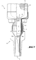
- Fig. 1 shows a partial section of a mixer according to the invention.
- the mixer 1 has an inlet opening 2 for feeding two components of a synthetic resin mortar into the Mixer 1 and an outlet opening 3, from which the, mixed in a static mixer Synthetic resin mortar can be used.
- the Threaded connector 4 In the area of the inlet opening 2 is the Threaded connector 4 with an internal thread 5 for connecting the mixer 1 to a housing arranged.
- An inner tube 6 is formed coaxially with the threaded connector 4, wherein the inner tube 6 extends out of the threaded connector 4 over this. Between the outer surface of the inner tube 6 and the inner surface of the threaded connector 4 a space 8 for receiving a connection piece of the housing is created. Of the Inner tube 6 becomes the receiving space 7 for receiving the partially hardened mortar mass created.
- FIG. 2 A partial section of the mixer arranged on a housing is shown in FIG. 2.
- the mixer 1 is screwed onto the connecting piece 12 of the housing 11.
- the film bag 13 with the hardener as the first component of the synthetic resin mortar and a further film bag 14 arranged in the film bag 13, which is arranged as second component of the synthetic resin mortar contains a reactive resin.
- a squeezing device applied to the film bag 13 or 14 are the film bags 13 and 14 opened and the two components are maintained by the Receiving space 7 fed to the static mixer, mixed there and via the outlet opening 3 the mixed synthetic resin mortar is used for further use.
- the top edge 15 of the inner tube 6 can be designed as a support edge for the film bag 13 or 14, which facilitates the opening of the film bags 13 and 14 by means of an extrusion pressure.
- the two components already react in the area of the recording space 7. With one Interruption of work partially hardens the partially mixed mass already in the receiving space 7 out. If the mixer 1 according to the invention is removed from the housing 11 by unscrewing it, the partially hardened mortar mass is completely removed in the receiving space 7. After connecting a new mixer 1, the remaining amount of the two components in the foil bags 13 and 14 can be used further.
Landscapes
- Engineering & Computer Science (AREA)
- Mechanical Engineering (AREA)
- Physics & Mathematics (AREA)
- Geometry (AREA)
- Package Specialized In Special Use (AREA)
Abstract
Ein Mischer (1) zum Mischen zumindest zweier Komponenten aus einem, in einem Gehäuse angeordnetem Folienschlauch mit einer ersten Komponente und zumindest einem, in dem ersten Folienschlauch angeordneten, zweiten Folienschlauch mit einer zweiten Komponente, weist am Gewindestutzen (4) einen zusätzlichen Aufnahmeraum (7) zur Aufnahme einer partiell ausgehärteten Zweikomponenten-Masse auf, der aus einem koaxial zum Gewindestutzen (4) angeordnetes Innenrohr (6) gebildet wird, das sich aus dem Gewindestutzen (4) heraus bis zum Folienbeutel erstreckt. Beim Auswechseln eines gebrauchten Mischers (1) gegen einen neuen Mischer (1) wird die, sich im Aufnahmeraum (7) befindliche Masse mit dem gebrauchten Mischer (1) entfernt und die im Folienbeutel vorhandene Restmenge der ersten und zweiten Komponenten kann weiterverwendet werden. <IMAGE>
Description
Die Erfindung betrifft einen Mischer zum Mischen zumindest zweier Komponenten aus einem,
in einem Gehäuse angeordnetem Folienschlauch mit einer ersten Komponente und
zumindest einem, in dem ersten Folienschlauch angeordneten, zweiten Folienschlauch mit
einer zweiten Komponente, wobei der Mischer einen Gewindestutzen für den Anschluss des
Mischers an einem Anschlussstutzen des Gehäuses umfasst.
Hochwertige chemische Befestigungen werden durch einen mehrkomponentigen Kunstharzmörtel
realisiert. Dabei enthält eine Komponente das Reaktionsharz und die andere
Komponente den Härter, wobei die beiden Komponenten in einem Mischer, beispielsweise
einem Statikmischer, zu dem Kunstharzmörtel vermischt werden. Als Gebinde für mehrkomponentige
Kunstharzmörtel werden beispielsweise Kunststoffkartuschen mit parallel angeordneten
Komponenten, Folienkartuschen mit parallel angeordneten Komponenten und Zusammenführungsteil
sowie Kunststoffkartuschen mit koaxial angeordneten Komponenten
verwendet.
Als weitere Gebinde für zweikomponentige Kunstharzmörtel sind Folienkartuschen bekannt,
bei denen in einem Folienschlauch, mit der ersten Komponente, ein weiterer Folienschlauch
ausgebildet ist, der die zweite Komponente enthält. Diese Folienschläuche können mit einfachen
Einkomponenten-Auspressgeräte ausgepresst werden und ergeben nach deren
Gebrauch eine geringe Abfallmenge. Beide Komponenten sind bis zu deren Verwendung
zuverlässig voneinander getrennt. Die Verbindung zwischen dem Folienschlauch und dem
Statikmischer wird mit einem Verbindungsteil geschaffen, an dessen einen Ende der Folienschlauch
anliegt und an dessen anderem Ende ein Aussengewinde für den Anschluss des
Statikmischers angeordnet ist. Indem der Verschlussclip durch den Anpressdruck abgestreift
oder der Folienschlauch vor dem Verschlussclip abgeschnitten wird, kann das Gebinde geöffnet
werden. Bei einem Arbeitsunterbruch härtet die im Mischer befindliche Masse aus und
der Mischer wird gegen einen neuen Mischer sowie der alte Folienschlauch gegen einen
neuen Folienschlauch ausgetauscht.
Nachteilig an der bekannten Lösung ist, dass die beiden Komponenten des Folienbeutels im
Verbindungsteil nicht mehr trennbar sind. Durch die zumindest partielle Vermischung der
Komponenten im Verbindungsteil wird die Härtungsreaktion ausgelöst. Bei einem Arbeitsunterbruch
kann der Restinhalt des Gebindes auch bei einem Austausch des Mischers nicht
mehr verwendet werden, da die gehärteten Mörtelanteile nicht mehr durch den Mischer passen
und diesen verstopfen.
Der vorliegenden Erfindung liegt die Aufgabe zugrunde, einen Mischer zu schaffen, bei dem
eine partiell ausgehärtete Mörtelmasse zusammen mit dem auszuwechselnden Mischer entfernt
wird.
Die Aufgabe ist durch die Merkmale des Anspruchs 1 gelöst. Gemäss der Erfindung umfasst
ein Mischer zum Mischen zumindest zweier Komponenten aus einem, in einem Gehäuse
angeordnetem Folienschlauch mit einer ersten Komponente und zumindest einem, in dem
ersten Folienschlauch angeordneten, zweiten Folienschlauch mit einer zweiten Komponente,
einen Gewindestutzen für den Anschluss des Mischers an einem Anschlussstutzen des Gehäuses.
Am Gewindestutzen ist ein zusätzlicher Aufnahmeraum zur Aufnahme einer partiell
oder vollständig ausgehärteten Zweikomponenten-Masse vorgesehen, wobei sich der Aufnahmeraum
aus dem Gewindestutzen heraus bis zum Folienbeutel erstreckt.
Mit dem erfindungsgemässen Mischer kann der im Wesentlichen gesamte Inhalt des Folienbeutel
auch bei einem oder mehreren Arbeitsunterbrüchen verwendet werden. Eine allfällige
partiell gemischte Mörtelmasse härtet in dem Aufnahmeraum aus und wird beim Mischerwechsel
vollständig entfernt. Nachdem der neue Mischer am Gewindestutzen des Gehäuses
angeordnet wurde, steht der Restinhalt des Folienschlauchs zu dessen weiteren Verwendung
zur Verfügung.
Vorzugsweise weist der Aufnahmeraum eine, aus dem Gewindestutzen ragende Kante auf,
die eine Auflagekante für den Folienbeutel zum Öffnen des Folienbeutels ist. Wird der Verschlussclip
durch den Auspressdruck des Auspressgeräts von dem Folienschlauch abgestreift,
muss eine Schulter für den Folienschlauch vorhanden sein, die dem Auspressdruck
entgegenwirkt. Diese Auflageschulter kann die, aus dem Gewindestutzen ragende Kante des
Aufnahmeraums sein.
Bevorzugt ist der Aufnahmeraum durch ein koaxial zum Gewindestutzen angeordnetes Innenrohr
gebildet. Der Abstand des Zwischenraums zwischen dem koaxial angeordneten Innenrohr
und der Innenwandung des Gewindestutzen des Mischers ist vorzugsweise derart
gross gewählt, dass die Wandung des Anschlussstutzens des Gehäuses in diesen Zwischenraum
eindringen kann.
Vorzugsweise ist der Mischer als Einwegteil ausgebildet. Die bei einem Arbeitsunterbruch im
Mischer befindliche Mörtelmasse härtet zumindest partiell aus. Der Mischer ist bevorzugt aus
einem Kunststoff gefertigt und ist als Massenprodukt günstig herstellbar.
Aus der nachfolgenden Detailbeschreibung und der Gesamtheit der Patentansprüche ergeben
sich weitere vorteilhafte Ausführungsformen und Merkmalskombinationen der Erfindung.
Die Erfindung wird nachstehend anhand eines Ausführungsbeispieles näher erläutert. Es
zeigen:
- Fig. 1
- Einen Teilaufschnitt eines erfindungsgemässen Mischers; und
- Fig. 2
- einen Teilaufschnitt des, an einem Gehäuse angeordneten Mischers.
Grundsätzlich sind in den Figuren gleiche Teile mit den gleichen Bezugszeichen versehen.
Fig. 1 zeigt einen Teilaufschnitt eines erfindungsgemässen Mischers. Der Mischer 1 weist
eine Eintrittsöffnung 2 zur Zuführung zweier Komponenten eines Kunstharzmörtels in den
Mischer 1 und eine Austrittsöffnung 3 auf, aus dem der, in einem Statikmischer gemischte
Kunstharzmörtel seiner Verwendung zuführbar ist. Im Bereich der Eintrittsöffnung 2 ist der
Gewindestutzen 4 mit einem Innengewinde 5 zum Anschluss des Mischers 1 an einem Gehäuse
angeordnet. Koaxial zum Gewindestutzen 4 ist in diesem ein Innenrohr 6 ausgebildet,
wobei sich das Innenrohr 6 aus dem Gewindestutzen 4 heraus über diesen erstreckt. Zwischen
der Aussenfläche des Innenrohrs 6 und der Innenfläche des Gewindestutzens 4 wird
ein Freiraum 8 zur Aufnahme eines Anschlussstutzens des Gehäuses geschaffen. Von dem
Innenrohr 6 wird der Aufnahmeraum 7 zur Aufnahme der partiell ausgehärteten Mörtelmasse
geschaffen.
Ein Teilaufschnitt des, an einem Gehäuse angeordneten Mischers ist in Fig. 2 dargestellt.
Der Mischer 1 ist an dem Anschlussstutzen 12 des Gehäuses 11 aufgeschraubt. Im Gehäuse
11 ist der Folienbeutel 13 mit dem Härter als erste Komponente des Kunstharzmörtels
und einem, im Folienbeutel 13 angeordneten weiteren Folienbeutel 14 angeordnet, der als
zweite Komponente des Kunstharzmörtels einen Reaktionsharz enthält. Durch vorgängiges
Aufschneiden des Folienbeutels 13 bzw. 14 oder durch einen mittels eines Auspressgeräts
auf den Folienbeutel 13 bzw. 14 aufgebrachten Druck werden die Folienbeutel 13 und 14
geöffnet und die beiden Komponenten werden bei Aufrechterhaltung des Drucks durch den
Aufnahmeraum 7 dem Statikmischer zugeführt, dort gemischt und über die Austrittsöffnung 3
wird der gemischte Kunstharzmörtel der weiteren Verwendung zugeführt. Die obere Kante
15 des Innenrohrs 6 kann als Auflagekante für den Folienbeutel 13 bzw. 14 ausgebildet sein,
die das Öffnen der Folienbeutel 13 und 14 mittels einem Auspressdruck erleichtert.
Die beiden Komponenten reagieren bereits im Bereich des Aufnahmeraums 7. Bei einem
Arbeitsunterbruch härtet die partiell gemischte Masse bereits im Aufnahmeraum 7 teilweise
aus. Wird der erfindungsgemässe Mischer 1 durch Abschrauben vom Gehäuse 11 entfernt,
wird die teilweise ausgehärtete Mörtelmasse im Aufnahmeraum 7 vollständig mitentfernt.
Nach Anschluss eines neuen Mischers 1 kann die Restmenge der beiden Komponenten in
den Folienbeutel 13 und 14 weiterverwendet werden.
Zusammenfassend ist festzustellen, dass mit dem erfindungsgemässen Mischer die vollständig
ausgehärtete, wie auch die nur partiell ausgehärtete Mörtelmasse zusammen mit
dem nach einem Arbeitsunterbruch auszuwechselnden Mischer entfernt wird.
Claims (3)
- Mischer zum Mischen zumindest zweier Komponenten aus einem, in einem Gehäuse (11) angeordnetem Folienschlauch (13) mit einer ersten Komponente und zumindest einem, in dem ersten Folienschlauch angeordneten, zweiten Folienschlauch (14) mit einer zweiten Komponente, der Mischer (1) umfasst einen Gewindestutzen (4) für den Anschluss des Mischers (1) an einem Anschlussstutzen (12) des Gehäuses (11), dadurch gekennzeichnet, dass am Gewindestutzen (4) ein zusätzlicher Aufnahmeraum (7) zur Aufnahme einer partiell oder vollständig ausgehärteten zumindest zweikomponentigen Masse durch ein koaxial zum Gewindestutzen (4) angeordnetes Innenrohr (6) gebildet ist, wobei sich das Innenrohr (6) aus dem Gewindestutzen (4) heraus bis zum Folienbeutel (13) erstreckt.
- Mischer nach Anspruch 1, dadurch gekennzeichnet, dass das Innenrohr (6) eine, aus dem Gewindestutzen (4) ragende Kante aufweist, die eine Auflagekante (15) für den Folienbeutel (13, 14) zum Öffnen des Folienbeutels (13, 14) ist.
- Mischer nach Anspruch 1 oder 2, dadurch gekennzeichnet, dass der Mischer (1) als Einwegteil ausgebildet ist.
Applications Claiming Priority (2)
| Application Number | Priority Date | Filing Date | Title |
|---|---|---|---|
| DE10240997A DE10240997A1 (de) | 2002-09-05 | 2002-09-05 | Mischer |
| DE10240997 | 2002-09-05 |
Publications (1)
| Publication Number | Publication Date |
|---|---|
| EP1396441A1 true EP1396441A1 (de) | 2004-03-10 |
Family
ID=31502381
Family Applications (1)
| Application Number | Title | Priority Date | Filing Date |
|---|---|---|---|
| EP03103256A Withdrawn EP1396441A1 (de) | 2002-09-05 | 2003-08-30 | Mischer |
Country Status (4)
| Country | Link |
|---|---|
| US (1) | US20040047233A1 (de) |
| EP (1) | EP1396441A1 (de) |
| CA (1) | CA2438585A1 (de) |
| DE (1) | DE10240997A1 (de) |
Families Citing this family (1)
| Publication number | Priority date | Publication date | Assignee | Title |
|---|---|---|---|---|
| DE102019123200B4 (de) * | 2019-08-29 | 2021-12-30 | Marco Systemanalyse Und Entwicklung Gmbh | Vorrichtung und verfahren zum zuführen eines flüssigen mediums |
Citations (4)
| Publication number | Priority date | Publication date | Assignee | Title |
|---|---|---|---|---|
| US3266682A (en) * | 1962-10-10 | 1966-08-16 | American Can Co | Container with snap-in plastic nozzle |
| US4585149A (en) * | 1982-10-27 | 1986-04-29 | Wella Aktiengesellschaft | Double container for two separated fluids |
| EP0581128A2 (de) * | 1992-07-31 | 1994-02-02 | GFV VERSCHLUSSTECHNIK GmbH & CO. | Spritzbehälter |
| DE19618693A1 (de) * | 1996-05-09 | 1997-11-13 | Upat Max Langensiepen Kg | Kartusche für Zweikomponentenmassen |
Family Cites Families (2)
| Publication number | Priority date | Publication date | Assignee | Title |
|---|---|---|---|---|
| GB9523230D0 (en) * | 1995-11-14 | 1996-01-17 | Courtaulds Packaging Ltd | A two-compartment container |
| DE19708548A1 (de) * | 1997-03-04 | 1998-09-17 | Struening Thomas | Mehrkammerschlauchfolienkartusche |
-
2002
- 2002-09-05 DE DE10240997A patent/DE10240997A1/de not_active Ceased
-
2003
- 2003-08-28 CA CA002438585A patent/CA2438585A1/en not_active Abandoned
- 2003-08-30 EP EP03103256A patent/EP1396441A1/de not_active Withdrawn
- 2003-09-04 US US10/654,679 patent/US20040047233A1/en not_active Abandoned
Patent Citations (4)
| Publication number | Priority date | Publication date | Assignee | Title |
|---|---|---|---|---|
| US3266682A (en) * | 1962-10-10 | 1966-08-16 | American Can Co | Container with snap-in plastic nozzle |
| US4585149A (en) * | 1982-10-27 | 1986-04-29 | Wella Aktiengesellschaft | Double container for two separated fluids |
| EP0581128A2 (de) * | 1992-07-31 | 1994-02-02 | GFV VERSCHLUSSTECHNIK GmbH & CO. | Spritzbehälter |
| DE19618693A1 (de) * | 1996-05-09 | 1997-11-13 | Upat Max Langensiepen Kg | Kartusche für Zweikomponentenmassen |
Also Published As
| Publication number | Publication date |
|---|---|
| DE10240997A1 (de) | 2004-03-18 |
| CA2438585A1 (en) | 2004-03-05 |
| US20040047233A1 (en) | 2004-03-11 |
Similar Documents
| Publication | Publication Date | Title |
|---|---|---|
| EP1246765B1 (de) | Adapter, anordnung und verfahren zur stoffentnahme aus mehrkammerschlauchbeuteln, verwendung des adapters sowie schlauchbeutelverpackung | |
| EP0209557B1 (de) | Vorrichtung zum dosieren von mindestens einem viskosen stoff | |
| DE602004003563T2 (de) | Abgabevorrichtung | |
| EP0721805A2 (de) | Vorrichtung zum Mischen und Ausbringen einer Formmasse | |
| DE19628552A1 (de) | Anti-Querkontamination-Doppelpatronenspender | |
| DE8900469U1 (de) | Vorrichtung zum Mischen und Ausbringen pastöser Massen | |
| DE102008040738A1 (de) | Foliengebinde | |
| EP2045196A2 (de) | Foliengebinde mit nebeneinander angeordneten Folienbeutelkammern | |
| DE20311287U1 (de) | Mehrkomponentenkartusche | |
| DE3826887A1 (de) | Schlauchfoermige verpackung aus flexiblem material fuer pastoese massen | |
| DE202006004738U1 (de) | Vorrichtung für das Mischen zweier Fluide | |
| CH674828A5 (de) | ||
| WO1991007333A1 (de) | Folienkartuschen für eine oder zwei komponenten zum einsetzen in dauerkartuschen für kittpistolen | |
| EP1396441A1 (de) | Mischer | |
| DE10310162A1 (de) | Kartusche zum Ausbringen von ein oder mehreren Komponenten einer Masse | |
| DE2922044A1 (de) | Verschlusskappe fuer eine tube | |
| EP1590263A1 (de) | Einstückiger doppelkammerbehälter | |
| DE2433716C2 (de) | 2-Komponentenverpackung | |
| DE2608690A1 (de) | Behaeltnis zur getrennten aufbewahrung von wenigstens zwei vor ihrer anwendung zu vermischenden komponenten | |
| EP1986929B1 (de) | Mehrkomponenten-kartusche | |
| EP0993864A1 (de) | Vorrichtung zur Durchführung einer mischenden Abgabe von mehreren fliessfähigen Komponenten | |
| DE102019101645A1 (de) | Applikationssystem mit zweifachem Originalitätsverschluss | |
| DE102008005743A1 (de) | Vorrichtung zur Lagerung von fluiden Komponenten für den dentalen Bereich | |
| WO2020151938A1 (de) | Applikationssystem mit verbesserter dichtung | |
| DE9302869U1 (de) | Vorrichtung zum Verteilen eines aus zwei Komponenten bestehenden Gemisches |
Legal Events
| Date | Code | Title | Description |
|---|---|---|---|
| PUAI | Public reference made under article 153(3) epc to a published international application that has entered the european phase |
Free format text: ORIGINAL CODE: 0009012 |
|
| AK | Designated contracting states |
Kind code of ref document: A1 Designated state(s): AT BE BG CH CY CZ DE DK EE ES FI FR GB GR HU IE IT LI LU MC NL PT RO SE SI SK TR |
|
| AX | Request for extension of the european patent |
Extension state: AL LT LV MK |
|
| AKX | Designation fees paid | ||
| REG | Reference to a national code |
Ref country code: DE Ref legal event code: 8566 |
|
| STAA | Information on the status of an ep patent application or granted ep patent |
Free format text: STATUS: THE APPLICATION IS DEEMED TO BE WITHDRAWN |
|
| 18D | Application deemed to be withdrawn |
Effective date: 20040911 |