EP1396462A2 - Vorrichtung zum Heben von Gegenständen, insbesondere Holzplatten - Google Patents
Vorrichtung zum Heben von Gegenständen, insbesondere Holzplatten Download PDFInfo
- Publication number
- EP1396462A2 EP1396462A2 EP03017724A EP03017724A EP1396462A2 EP 1396462 A2 EP1396462 A2 EP 1396462A2 EP 03017724 A EP03017724 A EP 03017724A EP 03017724 A EP03017724 A EP 03017724A EP 1396462 A2 EP1396462 A2 EP 1396462A2
- Authority
- EP
- European Patent Office
- Prior art keywords
- guide
- guide sleeves
- bores
- sleeves
- crossbar
- Prior art date
- Legal status (The legal status is an assumption and is not a legal conclusion. Google has not performed a legal analysis and makes no representation as to the accuracy of the status listed.)
- Withdrawn
Links
Images


Classifications
-
- B—PERFORMING OPERATIONS; TRANSPORTING
- B66—HOISTING; LIFTING; HAULING
- B66C—CRANES; LOAD-ENGAGING ELEMENTS OR DEVICES FOR CRANES, CAPSTANS, WINCHES, OR TACKLES
- B66C1/00—Load-engaging elements or devices attached to lifting or lowering gear of cranes or adapted for connection therewith for transmitting lifting forces to articles or groups of articles
- B66C1/10—Load-engaging elements or devices attached to lifting or lowering gear of cranes or adapted for connection therewith for transmitting lifting forces to articles or groups of articles by mechanical means
- B66C1/62—Load-engaging elements or devices attached to lifting or lowering gear of cranes or adapted for connection therewith for transmitting lifting forces to articles or groups of articles by mechanical means comprising article-engaging members of a shape complementary to that of the articles to be handled
- B66C1/66—Load-engaging elements or devices attached to lifting or lowering gear of cranes or adapted for connection therewith for transmitting lifting forces to articles or groups of articles by mechanical means comprising article-engaging members of a shape complementary to that of the articles to be handled for engaging holes, recesses, or abutments on articles specially provided for facilitating handling thereof
Definitions
- the invention relates to a device for lifting an object, in particular Wooden plate, wooden beam or wooden wide-stack element, with the attachment the device alone on the top of the object to be lifted takes place and can be carried out with little effort and effort and again is solvable.
- One way to do this is to lift the bottom of the Subject e.g. to carry one or more shoulder straps, the ends of which be guided upwards and subjected to the required lifting force.
- the disadvantage here is that the object to be lifted from its base must be spaced so that the shoulder strap is arranged in a suitable manner can be.
- the object to be lifted must first either lifted by hand or using a suitable auxiliary mechanism be or on supports through which he is sufficient of his pad is spaced, stored, which means a considerable effort.
- suitable suspension elements such as Attach screw hooks or eyelets.
- An advantage here is that the attachment of suitable suspension elements in many cases from the top of the object to be lifted is possible, so that the object to be lifted is not off its surface must be spaced.
- the disadvantage here is that with the attachment suitable suspension elements connected considerable effort.
- the disadvantage is the need for the attached suspension elements to remove later, e.g. because they're handling that space-saving storage, processing or use of the obstacle to lifting object or e.g. for cost reasons to be reused for lifting other objects.
- Another possibility is to lift the object to be lifted its side surfaces with a suitable mechanical gripping mechanism to understand.
- the disadvantage is that the gripping mechanism in many Cases specifically according to the dimensions or shape of the lifting objects must be trained. Furthermore, here is in disadvantageous in many cases that the side surfaces of the objects to be lifted are subjected to heavy use by the gripping process, what especially with frequent repetition of damage or Wear of the object to be lifted.
- Another possibility is to use one or more suction devices for lifting an object.
- the disadvantage here are This requires great effort and the limitation of applicability on objects with sufficiently tensile, smooth surfaces.
- 199 62 127 C2 is a device for lifting objects, in particular known wooden panels, wooden beams or wooden wide stacking elements.
- This device comprises a rigid compression rod on which in the area the ends of which each engage a tension rod, each at their upper ends are connected to a connecting bridge and together with the pressure rod as Base an isosceles triangle on the base.
- At the ends of the Pressure rod are oblique guide sleeves that serve as drilling templates are arranged, their longitudinal axes in one plane with the triangle lie and intersect at a point below or above the Pressure rod is close to or in the projection of its center.
- In the Guide sleeves are manually insertable, which after inserting the Extend the guide sleeves below the pressure rod.
- the one to be lifted The object has at least two holes that continue in the Guide sleeves have been drilled diagonally into the object.
- the the Part of the mandrel protruding downwards can be turned into one of each Bores engage, making the device releasable with the one to be lifted Object is connected.
- the pressure rod is hinged to the Tension rods articulated that the compression rod by one to its longitudinal direction parallel axis can be pivoted relative to the tension rods.
- a disadvantage of this lifting device is the possibility that the Incorrectly insert mandrels into the guide sleeves, without being noticed.
- spines which were initially fully inserted into the guide sleeves, e.g. by virtue of of vibrations gradually move out of the holes.
- the mandrels are not or no longer far engage enough in the holes and therefore out with the lifting material lifted break out the holes laterally, which is not only serious damage of the goods to be lifted, but also a serious security risk represents.
- Another disadvantage of this lifting device is that tilting moments and bending stresses occur when the projection of the point of application of the Lifting power compared to the projection of the center of gravity of the to be lifted Object is moved transversely to the longitudinal direction of the pressure rod.
- This can also be conventionally provided by joints, a pivotal movement of the raised object against the Tension rods to allow an axis parallel to the cross member, not completely avoid what is structurally disadvantageous and the risk of Broken material increased.
- the invention is based on the object of the disadvantages mentioned avoid, as it is based on the task, a device for To provide lifting of objects regardless of the surface condition of the object to be lifted, where the attachment of the object to be lifted only from the front can be repeated as often as desired with very little material effort and with very little effort and effort very quickly and again can be solved without hanging elements on the lifting to be lifted To attach the object without exposing it to wear and tear without first having to distance it from its base.
- the longitudinal axes of the guide sleeves do not necessarily have to be in intersect a point, i.e. the longitudinal axes do not have to be in one plane lie. Rather, they can be mutual in a certain mutual Cross the minimum distance without lying in one plane.
- the area in which the longitudinal axes cross is the area of the intersection or the area in which the least mutual Decency between the longitudinal axes is reached.
- the object is further achieved by a lifting device for lifting a Object, in particular wooden panel, wooden beam or wooden board stacking element, which two of the devices explained above with a total of four tension elements comprises which two devices so by means of a traverse coupled that a lifting force acting on the crossbar at the same time can be introduced into the object via all four tension elements.
- the lifting force required to lift the object can e.g. by a crane are exercised and will be at the top of the triangle or at the top Short side, i.e. the side of the square opposite the cross beam initiated device according to the invention. This is according to the invention able to apply the lifting force to the object to be lifted.
- the device according to the invention is to be lifted Object preferably placed so that the triangle or Square spanned plane stands vertically and through the center of gravity of the lifting object runs and the point at which the lifting force is introduced into the device, in the vertical projection of the center of gravity of the object to be lifted.
- Can advantageously be used for lifting an object also uses two or more devices become.
- the object to be lifted is provided with holes once, the Longitudinal axes coincide with those of the guide sleeves, the The diameter of the holes corresponds at least to that of the mandrels.
- the guide sleeves can be according to an embodiment of the invention can be used advantageously as drilling templates.
- the holes can completely penetrate the object to be lifted, However, they are particularly important if the object to be lifted is sufficient Has thickness, preferably designed as blind holes, so that the underside of the object to be lifted can remain unchanged and the holes are invisible from below. This is especially true of great advantage if the objects to be lifted are installed later that only its underside is visible, e.g. Elements of a Ceiling covering for a living room.
- the thorns are used for the device according to the invention through the guide sleeves into the Holes introduced.
- Each of the mandrels preferably has a handle.
- the longitudinal axes of the guide sleeves take one according to the invention such an angle with respect to the vertical that they are at one point cross, which is below or above the crossbar and its vertical projection on the cross bar between the points of attack. Therefore, the mutual distance between the lower ends of the in the guide sleeves and drilling inserted mandrels either less or greater than the mutual distance of their upper ends. So one is at the top of the triangle or on the top transverse side of the square vertically upwards attacking lifting force over the tension elements, the cross bar, the mandrels and either the inwardly facing parts of the walls of the holes or the outwardly facing part of the walls of the holes in the initiated lifting object.
- the device can thus according to the invention in very short time and with very little effort and effort as often as you like repeatedly attached to the object to be lifted and again by same be solved.
- the mandrels are each means a releasable locking mechanism against displacement of the mandrels can be secured relative to the guide sleeves in the longitudinal direction thereof.
- the locking mechanism is set up that if the mandrel is not fully inserted into the guide sleeve cannot be activated, i.e. the locking mechanism only allows locking the mandrel when it is fully inserted; otherwise it is no locking possible.
- the locking mechanism can be designed that he is able to move automatically under the influence of gravity activate.
- the locking mechanism can have a locking element, which can be moved between a locked position and a release position, wherein the locking element is an upward movement of the fully into the guide sleeve inserted mandrel opposite the guide sleeve in the locked position essentially blocked and not blocked in the release position, and one that arises when a tensile force is applied to the tensile element Force component the locking element when completely in the guide sleeve inserted mandrel is able to move into the locked position.
- the blocking element able to exert a force on the mandrel, which completely into the mandrel Is able to insert the guide sleeve.
- the locking mechanism can be e.g. Locking mechanism or a locking mechanism or a screw mechanism or a cotter pin mechanism and secures the mandrel e.g. against erroneous removal or against a gradual, unnoticed emigration from the borehole.
- the locking mechanism can e.g. be designed as a locking mechanism, which the Mandrel automatically engages with the guide sleeve as soon as the mandrel is complete is inserted.
- the locking mechanisms are each as Split pin mechanisms formed, each of the guide sleeves two diametrically opposed side bores and each mandrel one Has cross bore and the side bores and the cross bore each are arranged so that when fully inserted into the guide sleeve Pin to lock the same in the guide sleeve a pin in the Cross hole and the side holes is insertable that this The guide sleeve and the mandrel inserted into it protrude in each case.
- the locking mechanism can advantageously be coupled to a warning device be which, when the locking mechanism is not activated, is an optical and / or is able to trigger an acoustic warning signal. That way prevent it from going unnoticed if a thorn just mistakenly is inserted incompletely into the guide sleeves or if it is mistakenly not activated locking mechanism begins to migrate from the hole.
- the warning device can be designed such that It only triggers the warning signal when an object is attempted with the help of a tool according to the invention during the Locking mechanism is not activated.
- the warning device can e.g. one Quiescent current contactor and a siren or flashing light connected to it include, the contactor when not fully inserted Dorn releases the power supply to the siren or flashing light and otherwise interrupts.
- the invention is Device on an electrically operated lifting device, in particular a crane, arranged and the locking mechanism coupled to an interrupter, which, when the locking mechanism is not activated, powers the Is able to interrupt lifting device.
- an electrically operated lifting device in particular a crane
- the locking mechanism coupled to an interrupter, which, when the locking mechanism is not activated, powers the Is able to interrupt lifting device.
- the cross member is in the Area of a point of attack from a first tab and in the area of other point of attack by a second rider ring or sleeve-like is surrounded, which in each case opposite the cross bar around it Longitudinal axis are rotatable, the first tension element with its lower End at the first rider and the second traction element with its lower one End attacks on the second rider, leaving the cross member in the riders rotatably and opposite the plane of the triangle or quadrangle is rotatable about its longitudinal axis.
- the inner surfaces of the tab can be at a rotation of the cross bar around its axis act as a slide bearing.
- the cross member and the one with the invention Device always lifted object under the influence of gravity pivot about the longitudinal axis of the crossbar so that the Center of gravity of the raised object essentially in the plane of the triangle spanned by the tension rods and the cross member.
- This prevents tilting moments and bending stresses from occurring if the projection of the point at which the e.g. from a crane outgoing lifting force is introduced into the device against the Projection of the center of gravity of the object to be lifted transversely to the Longitudinal direction of the cross member is shifted.
- this embodiment is the Querholm a as a cylinder rod and the tabs each as cylindrical sleeves formed, through which the cross member is carried out, the Inner diameter of the sleeves essentially the outer diameter of the Querholmes corresponds.
- a first and a second lifting eye can be attached to the first and second tabs be arranged on which by means of a first or second lower. Hinge pin the first or second tension element with its lower end is articulated so that the location of the points of attack by the location of the load eyes is determined.
- the cross member can according to another embodiment of the invention Reduction of friction by means of a roller bearing or ball bearing the first and second tab can be rotatably added.
- the two tabs can be mechanically rigidly connected to one another.
- the two tabs can be moved through a single one Pipe piece be formed, one end of which is the first tab and its other end acts as a second tab.
- they can be replaced by a single continuous one Tube piece be formed, one end of which as the first sleeve and the other end acts as a second sleeve.
- the tabs or sleeves are not rigidly connected.
- the cross bar can be a first or second Have stop, which is a displacement of the rider in the longitudinal direction to prevent or limit the crossbar to the center of the same is able.
- the tension elements are preferably designed as tension rods. Here you can Change the angle of the triangle or quadrangle with its tension rods upper ends articulated with each other and the first or second tension rod with its lower end articulated to the first or second tab his.
- training the tension elements as tension rods is not mandatory required.
- the tension elements can each be a chain be trained.
- the tension elements are arranged next to each other, tension the tension elements together with that between the points of attack lying part of the crossbar essentially a triangle. if the the upper ends of the tension elements are spaced apart, the tension Tension elements together with the part lying between the points of attack of the cross member essentially a quadrilateral, the upper transverse side, i.e. its side opposite the cross beam by a connecting bridge can be formed.
- the Tension elements of the same length If the tension elements together with the part of the crossbar lying between the points of attack essentially spanning a triangle, this triangle is the same in the case of the same length Isosceles tension elements. If the tension elements together with the part of the crossbar lying between the points of attack essentially span a square and the corners of the square are articulated, this is how it is Square in the case of equal length of the tension elements and more symmetrical Load distribution an isosceles trapezoid, i.e. a trapeze, both of which Sloping sides are the same length.
- the cross member consists of two telescopically slidable beams, one of the tension elements on one beam and the other of the tension elements on the other Beam attacks.
- the guide sleeves are preferred arranged that their longitudinal axes intersect at a point that below the crossbar is near or in the projection of its center, and the The longitudinal axes of the guide sleeves lie in a plane with the triangle.
- the lifting tool can be stepped on different mutual spacings of the holes can be adjusted, especially if the sides of the triangle or quadrilateral pass through Joints are connected. If the tension elements together with the part of the crossbar lying between the points of attack essentially span a triangle.
- the angles of the Triangle and the length of the base of the triangle is variable while the length the other two sides is constant.
- the guide sleeves take such an angle with respect to the vertical that they intersect at a point below the crossbar is near the projection of its center.
- the longitudinal axes intersect the guide sleeves at a point which is above or below the Querholmes is near or in the projection of its center, the Longitudinal axes of the guide sleeves in one plane with the triangle or Trapeze lying.
- the longitudinal axes of the guide sleeves intersect at a point which by a maximum of 10% of the mutual distance of the attack points from the Projection of the center of the crossbar is removed.
- the traction elements can each have a common one at their upper ends Connection bridge can be arranged or hinged, which is a suspension element, Has hook or eye.
- the Guide sleeves can be used as drilling templates for making the holes.
- the mandrels preferably each have an essentially cylindrical shaft which is at least partially insertable into the guide sleeves.
- the shafts can on their outer surface one over the same to the outside have protruding stop element which acts as a sliding block, and the guide sleeves each have a channel-like or slot-like wall
- the guide sleeves each have a channel-like or slot-like wall
- a slide guide which is shaped and in which one the stop elements engages in such a way that the travel paths of the shafts in the longitudinal direction the guide sleeves through the interaction of the link guide and the stop element engaging in them are each limited.
- the shafts due to the interaction of the link guide and the stop element cannot be removed from the guide sleeves and therefore cannot be lost.
- the link guides preferably each run at least partially in Longitudinal direction of the guide sleeves.
- the backdrop guides in each case in its lower end area transversely to the longitudinal direction of the guide sleeves run, so that each stem against a procedure of the same in Longitudinal direction of the guide sleeves can be locked by the stop element is brought into engagement with the lower end region of the link guide, and / or in each case in their upper end region transverse to the longitudinal direction of the Guide sleeves run so that each shaft opposes a movement of the same can be locked in the longitudinal direction of the guide sleeves by the stop element engaged with the upper end portion of the link guide becomes.
- Each slide guide can advantageously be essentially Z-shaped Have course, the upper line of the Z through the upper end region the link guide and the lower line of the Z through the lower end area the backdrop guide is formed. and the scenery tour together with the Stop element forms a locking mechanism.
- the middle line of the Z can in particular in each case parallel to the longitudinal direction of the guide sleeves run.
- the stop elements can each be designed as a handle, which for manual handling of the mandrels.
- the shafts can each have a marker on their lateral surfaces, which is only visible from the outside when the shaft is inserted into the guide sleeve, if the stop element with the upper end region of the link guide in Intervention, or is only visible from the outside if that Stop element engages with the lower end region of the link guide brought.
- the markers can e.g. using fluorescent paint or e.g. by means of a Light source be formed; their visibility indicates that the spines are in one determined against a movement of the same in the longitudinal direction of the Guide sleeves locked position.
- two devices according to the invention can be combined into one Lifting device for lifting an object, in particular a wooden plate, wooden beams or wood wide-stack element, coupled, such a lifting device two of the devices according to the invention and thus a total of four Includes tension elements, the two devices according to the invention by means a crossbar are coupled so that a lifting force acting on the crossbar can be introduced into the object simultaneously via all four tension elements.
- a drilling template to assist in the production of the holes in the object which to be lifted with a device is instead of the device Item can be placed and has a crossbar in the end regions each arranged an oblique drilling template sleeve open on both sides whose longitudinal axes are the longitudinal axis of the crossbar below the same Cut angles at which the guide sleeves the longitudinal axis of the Cut crossbars, and through which a drill for making the Bores can be inserted and which are able to guide the Serve drill, the mutual spacing of the template sleeves the mutual distance between the guide sleeves in the same and in the Holes inserted thorns corresponds, so that with the help of Drilling template the holes can be made so that the location and Orientation of the holes through the position and orientation of the template sleeves is determined, and with the longitudinal axis of each of the guide sleeves one of the holes can be made to coincide with
- the drilling template according to the invention preferably has on its underside at least one support plate on which the drilling template is placed on allows the object in a defined, stable position.
- the drilling template therefore has at least one vertical fixing sleeve open on both sides, into which a Fixing bolt can be inserted so that the same after one of the holes has been produced with the help of the drilling template, without changing the position of the Drilling template engages in this hole and in this way translational sliding of the drilling template relative to the object in derogation. In this way it can advantageously be prevented that the Unintentionally moved the drilling template on the object to be lifted before the second hole has been drilled.
- the Fixing sleeve on the same inner diameter as the guide sleeves, so that the mandrels can be used as fixing bolts.
- the Crossbar in the area of their center related to their longitudinal direction Marking to visually identify the center of the crossbar. This Marking facilitates the drilling of the holes symmetrically to the solder the center of gravity of the object to be lifted.
- the invention includes also a set consisting of at least one according to the invention Device and a drilling template according to the invention.
- Fig. 1 shows a schematic side view of a preferred embodiment a device according to the invention, which is to be lifted Item 14 is placed, which e.g. a wooden plate, a wooden beam or can be a wide-pile wood element.
- the device comprises one rigid cross beam 1, which is shown in Fig. 1 in cross-sectional view and which consists of a first and a second bar 1a, 1b.
- the first beam 1a consists of a rod 1d and a connecting rod 1e, which protrudes telescopically into the interior of the rod 1d and rigidly attached, e.g. welded or screwed to it.
- the second bar 1b is a hollow profile with a circular cross section educated.
- the connecting rod 1e is circular as a full profile Cross section formed, the outer diameter of the connecting rod 1e essentially the inside diameter of the second beam 1b equivalent.
- the longitudinal axes of the first bar 1a, the second bar 1b and the connecting rod 1e essentially coincide and form together the longitudinal axis 1c of the cross member 1.
- the connecting rod 1e protrudes telescopically into the interior of the first with part of its overall length Beam 1a into it, but is not attached to it.
- the bars 1a, 1b can therefore slide telescopically in the direction of the longitudinal axis 1c be moved against each other.
- the two beams 1a, 1b of the cross bar 1 rigidly connected to each other by the connecting rod 4
- the device of FIG. 1 further comprises a first and a second Tension rod 3a, 3b, which at their upper ends each by means of an upper Articulated bolt 12a and 12b articulated on a connecting bridge 2 and are thus articulated together.
- the connecting bridge 2 is with a suspension element 8 provided, e.g. a pull hook can be attached.
- the tension rods 3a, 3b engage at spaced apart points of attack each on the cross member 1.
- the first tension rod 3a engages with his lower end on a first tab 20a, with which the first tie rod 3a via a load eye 21a attached to the first rider 20a and one lower hinge pin 11a is articulated.
- the second tension rod also applies 3b with its lower end on a second tab 20b with which the second tension rod 3b via a load eye attached to the second tab 20b 21 b and a lower hinge pin 11b is articulated.
- the first tab 20a is in the area of one end of the crossbar 1, the other riders 20b in the area of the other end of the cross member 1 arranged so that the first tension rod 3a via the first tab 20a in Area of one end of the cross member 1 and the second tie rod 3b over the second tab 20b in the area of the other end of the cross member 1 attacks the same.
- the upper ends of the tie rods 3a, 3b are apart somewhat spaced and articulated with each other via a connecting bridge connected.
- the tension rods 3a, 3b which are of the same length, clamp together with the part of the cross member 1 located between the riders 20a, 20b in the essentially an isosceles trapezoid whose base is covered by the between the riders 20a, 20b part of the cross member 1 is formed.
- the Legs of the trapezoid are through the tie rods 3a, 3b, the upper transverse side of the Trapezes formed by the connecting bridge 2.
- Fig. 1 is the mutual distance of the upper ends of the tie rods 3a, 3b relatively small, so that the trapezoid in the example of Figure 1 approximately the shape of a has isosceles triangle.
- the tabs 20a, 20b are each sleeves 20a, 20b of circular cross-section trained, which are pushed over the cross bar 1 and this surrounded peripherally, the inner diameter of the sleeves 20a, 20b essentially corresponds to the outer diameter of the cross member 1.
- the cross beam 1 is thus rotatable about its longitudinal axis 1c in the sleeves 20a, 20b added and can therefore be compared to the plane of the trapezoid that passes through the cross member 1 and the tie rods 3a, 3b is clamped, are rotated.
- Each of the two bars 1a, 1b rigidly indicates one near its outer end the oblique guide sleeve 5a, 5b attached to the beam 1a or 1b in which a mandrel 6a, 6b can be inserted, the Longitudinal axes of the guide sleeves 5a, 5b in the plane of through the two Tension rods 5a, 5b and the cross member 1 are formed trapezes and themselves intersect a point below the crossbar 1 near the projection is in the middle.
- the vertical projection of this point on the cross bar therefore lies between the riders 20a, 20b and thus between the points of attack, at which the lower ends of the tie rods 3a, 3b on the cross member Attack 1.
- the inner diameter of the guide sleeves 5a, 5b essentially corresponds the outer diameter 6a, 6b of the mandrels, so that they are easy but without Allow large play to be inserted into the guide sleeves 5a, 5b.
- the mandrels 6a, 6b are preferably each for reasons of simple manual handling provided with handles 7 at their upper ends.
- the device is placed on the object 14 to be lifted.
- the too lifting object 14 was previously provided with holes 15 once, whose longitudinal axes coincide with those of the guide sleeves 5a, 5b, so that the guide sleeves 5a, 5b advantageously as drilling templates for Production of the holes 15 can be used.
- the cross bar 1 each have a support plate 22 with a flat underside, which a rotation of the cross bar 1 relative to the to be lifted Object 14 is prevented when the device according to the invention from FIG. 1 rests on it. Furthermore, the support plates 22 act as spacers, which have a direct contact between the sleeves 20a, 20b and Prevent the surface of the object 14 to be lifted.
- the mandrels 6a, 6b are inclined through the guide sleeves 5a, 5b in each one of the bores 15 can be inserted into the object 14 to be lifted.
- Fig. 1 is the first mandrel 6a completely inserted into the guide sleeve 5a Condition shown; the mandrel 6a projects downwards over the guide sleeve 5a and engages in the bore 15.
- the second mandrel 6b is not yet in FIG Guide sleeve 5b inserted.
- Suspension element 8 attacking vertically upwards, e.g. from a crane applied lifting force that on the two beams 1a, 1b along their Longitudinal axis 1c each has a force component so that the mutual Distance of the outer ends of the bars 1a, 1b is reduced.
- the consequence is one Automatically generated lateral pressure of the mandrels 6a, 6b against the walls of the bores 15, the one according to the invention Intensification of the mechanical bond between the mandrels 6a, 6b and the object 14 to be lifted.
- the mandrels 6a, 6b are each detachable Locking mechanism against displacement of the mandrels 6a, 6b opposite the guide sleeves 5a, 5b can be secured in the longitudinal direction thereof.
- each of the mandrels 6a, 6b has a transverse bore 23a or 23b; furthermore, for this purpose each of the guide sleeves 5a, 5b points two towards one another each have diametrically opposite side bores 24.
- the two side bores 24 of the guide sleeve 5a and the cross bore 23a of the mandrel 6a are each arranged so that when fully in the Guide sleeve 5a inserted mandrel 6a a cotter pin in the Cross bore 23a and the two side bores 24 of the guide sleeve 5a it is insertable that the cotter pin the guide sleeve 5a and the therein inserted mandrel 6a extends transversely to their longitudinal axis, so that the cotter pin projects beyond the guide sleeve 5a on both sides.
- the two side bores 24 of the guide sleeve 5b and the transverse bore 23b of the mandrel 6b each arranged so that when fully in the Guide sleeve 5b inserted mandrel 6b another pin in the way Cross bore 23b and the two side bores 24 of the guide sleeve 5b it is insertable that the cotter pin the guide sleeve 5b and the therein inserted mandrel 6b projects transversely to their longitudinal axis, so that the cotter pin also protrudes over the guide sleeve 5b on both sides (the Pin bolts are not shown in Fig. 1).
- two of the side bores 24 form together with one of the transverse bores 23a, 23b and one of the cotter pins one as Split pin mechanism 23a, 24 or 23b, 24 designed locking mechanism, which is able to prevent the mandrels 6a, 6b from shifting the mandrels 6a, 6b with respect to the guide sleeves 5a, 5b in the longitudinal direction thereof secure when the mandrels 6a or 6b completely into the guide sleeves 5a or 5b are inserted.
- the cotter pin mechanism is activated when the cotter pin is in the cross hole 23a and 23b and the two side bores 24 of the guide sleeve 5a and 5b is inserted and protrudes through each. To do this, the Projections of the side bores 24 with the projection of the transverse bore 23a or 23b are made to coincide; then the cotter pin inserted and the pin mechanism activated.
- the locking mechanism does not necessarily need to to be a cotter pin mechanism. Rather, it can e.g. as a locking mechanism, Screw mechanism or snap mechanism can be formed.
- the guide sleeve a side bore and the mandrel one have spring-loaded hemisphere protruding laterally from the same, which is able to snap into the side hole.
- FIG. 2 shows a cross-sectional view through a sleeve 20a 'with a lifting eye 21a', the sleeve 20a 'is penetrated by a bar 1a'.
- the cutting direction of the 2 runs perpendicular to the axis 1c 'of the beam 1a' and is marked in Fig. 3 with arrows, which are denoted by the letters A are marked.
- the sleeve 20a ', the load eye 21a' and the beam 1a ' correspond with regard to their function of the sleeve 20a, the lifting eye 21a and the beam 1a of Fig. 1.
- the load eye 21a ' is rigidly connected to the sleeve 20a', e.g. welded.
- the sleeve 20a 'and the bar 1a' each have one circular cross-section, wherein the inner diameter of the sleeve 21a 'in substantially corresponds to the outer diameter of the beam 20a 'and the Beam 20a 'relative to the sleeve 21a' is rotatable about the axis 1c '.
- the Load eye 21a ' has a bore 27 for receiving a hinge pin, by means of which a tension rod, not shown, is articulated on the sleeve 20a ' can be.
- Fig. 3 shows the sleeve 20a 'and the outer end portion of the beam 1a' of Fig. 2 with a guide sleeve 5a ', which is rigid via a connector 28 is attached to the beam 1a '.
- the sleeve 20a ' is in Fig. 3 in Cross-sectional representation shown.
- the axis of the guide sleeve closes with the Axis 1c 'of the beam 1a' forms an angle of 51 ° and points at its lower one End in a support plate 22 '.
- the guide sleeve has two diametrically opposite one another Side bores 24 ', which in relation to the viewing direction of FIG. 3rd lie congruently one behind the other.
- One cannot into the guide sleeve 5a ' Insert the mandrel with the cross hole so that the axis of the Cross bore coincides with the axes of the side bores 24 ', so that According to the invention a split pin for releasable locking of the mandrel in the Side holes and the cross hole can be inserted.
- the Guide sleeve 5a ', the side bores 24', the stop 26a 'and the support plate 22 ' correspond to the function of the guide sleeve 5a Side bores 24, the stop 26a and the support plate 22 of FIG. 1st
- FIG. 4 and 5 relate to a further embodiment of the invention, which is modified from that of Fig. 1 and a locking mechanism has, which is advantageously able to under the Activate the influence of gravity automatically.
- the device of FIGS. 4 and 5 differs from the device of FIG Fig. 1 in that the lifting eyes 21a, 21b not on the sleeves 20a, 20b are attached, but each on a carriage 30a or 30b, which opposite the sleeve 20a or 20b parallel to the direction of the cross member axis 1c slidable between a release position and a blocking position, wherein the movement of the carriages 30a and 30b by two mutually aligned, spaced guides 29a and 29b is slidably guided.
- the Guides 29a and 29b are rigidly attached to the sleeve 20a, by the Slides 30a and 30b protrude through and also serve as stops for the Load eye 21a or 21b, which the displacement path of the carriage 30a or 30b limit.
- the load eyes 21a and 21b are rigid on the carriage 30a and 30b attached, e.g. welded.
- the mandrels 6a, 6b are rotated by 90 ° about their longitudinal axis compared to FIG. 1, so that the end faces of the handles 7 in the plane of the drawing of FIG. 4 and FIG. 5 lie.
- the guide sleeves 5a, 5b and the mandrels 6a, 6b are preferably like this set up that with mandrel 6a or 5b inserted into the guide sleeve or 6b this is not rotatable about its longitudinal axis.
- the guide sleeves 5a or 5b and the mandrels 6a or 6b can be used for this purpose e.g. each have a square cross section.
- the slides 30a, 30b are each in the release position in FIG. 4, in FIG. 5 each shown in the locked position.
- a blocking element 31a or 31b is rigidly arranged, which therefore participates in the movement of the sled and thus together with the carriage 30a or 30b between the release and the Locked position is movable.
- the locking elements 31a, 31b are in each case sufficiently far from the handles 7 of the mandrels 6a and 6b so that the mandrels 6a and 6b each freely in the direction of their longitudinal axis can be removed from the guide sleeves 5a and 5b.
- the locking elements 31a, 31b are each so on the handles 7 that the mandrels 6a and 6b along their respective Longitudinal axis cannot be moved upwards and are therefore locked.
- the locking elements 31a and 31b block in the respective locking position each an upward movement of the completely into the guide sleeve 5a or 5b inserted mandrel 6a or 6b opposite the guide sleeve 5a or 5b, whereby the mandrels 6a, 6b are each locked according to the invention.
- the slides 30a and 30b thus form together with the guides 29a and 29b and the locking elements 31a and 31b each have a locking mechanism 29a, 30a, 31a and 29b, 30b, 31b, which is advantageously able to itself activate automatically under the influence of gravity.
- the locking element 31a or 31b advantageously able to exert a force on the mandrels 6a and 6b, which pushes it completely into the guide sleeve 5a or 5b.
- the locking elements 31a, 31b be moved manually or spring-loaded back to the release position, which releases the lock.
- an optical or acoustic warning signal be provided, which always lights up when the pins 6a, 6b are not locked or sounds.
- Can on the handle 7 and on the locking element 31a and 31b each have an electrical contact surface arranged so that the Touching contact surfaces and thereby a circuit is closed, when the locking element 31a or 31b rests on the handle 7 as in FIG. 5 shown.
- the warning signal can be switched off by this circuit are indicated, which indicates the proper locking of the mandrels.
- the cross bores 23a, 23b and the side bores 24 of FIG. 1 are not required for the embodiment of FIGS. 4 and 5 and can therefore not applicable there.
- FIG. 6 shows a schematic side view, not to scale, of another one Embodiment of a device according to the invention, which on the lifting object 14 is placed.
- the device of FIG Fig. 6 no riders.
- Tension rods 103a, 103b are each on one Link bridge 102 hinged and thus articulated with each other connected.
- the lower ends of the tie rods 103a, 103b are at opposite ends End regions of a cross member 101 articulated.
- the Connecting bridge 102 is provided with a suspension element 108 which via a rope 9 a e.g. lifting force applied by a crane attacks; this lifting force is in Fig. 6 by an upward arrow illustrated.
- the mandrels 106a, 106b of Fig. 6 are inserted deep into guide sleeves 105a, 105 and into the bores 15 and each have a handle 107, which from the upper end of the mandrel 106a or 106b protrudes on one side.
- the function, arrangement and Alignment of the guide sleeves 105a, 105b corresponds essentially to that Function, arrangement and alignment of the guide sleeves 5a, 5b of Fig. 1st
- FIG. 7 shows a perspective view of a further embodiment of a Device according to the invention, which is a modification of the device of Fig. 6 is the object to be lifted is not shown in Fig. 7.
- the device of FIG. 7 is the first Pull rod 103a is at its lower end on a first tab 120a articulated and second tension rod 103b with its lower end to a second Rider 120b articulated. Both tabs 120a, 102b are located in the area one end of a crossbar 101 '.
- the function of tabs 120a, 120b corresponds to that of the tabs 20a, 20b of the device of FIG. 1 Travel path of the riders 120a, 120b in the direction of the center of the cross member 101 ' limited by stops, which are not shown in Fig. 7.
- the mandrels 106a, 106b are each detachable Locking mechanism A, K, each consisting of a link guide K and a stop element A, against a displacement of the mandrels 106a, 106b with respect to the guide sleeves 105a, 105b in the longitudinal direction thereof securable.
- the way this locking mechanism A, K works is shown below 11 with reference to.
- the stop element A is not in FIG. 7 shown.
- Fig. 8 shows schematically in perspective a lifting device with two 6, which are coupled by means of a traverse T, in a first preferred spatial arrangement in which the longitudinal axes the cross bars 101 of both devices run parallel to one another and are spaced from each other.
- the cross bars 101 are on the to be lifted Object 14 arranged opposite to each other so that the Stretch the end points of the cross bars 101 in a rectangle.
- the two devices shown in FIG. 8 according to FIG. 6 have a total of four tension elements 103a, 103b and are so by means of the traverse T. coupled that a lifting force acting on the traverse, which is shown in FIG is illustrated by an upward arrow and over a cross rope Q is transferred to the end points of the traverse T, simultaneously over all four Pulling elements 103a, 103b can be introduced into the object 14 to be lifted.
- Fig. 9 shows the lifting device of Fig. 8 in cross-sectional representation in a second preferred spatial arrangement in which the longitudinal axes of the Cross bars 101 of both devices are aligned. This arrangement is particularly suitable for lifting very long beams. Also through this Arrangement is the introduction of force into the object 14 from two to four Zones distributed, which increases the load-bearing capacity and the deflection of the Item 14 under its own weight when raised can be reduced.
- the drilling template 200 is instead of one device according to the invention, e.g. the device of Fig. 7, on object 14 attachable. It has a crossbar 201, one in each of its end regions oblique drilling template sleeve 205a, 205b open on both sides is arranged.
- the longitudinal axes of the drilling template sleeves 205a, 205b intersect the Crossbar 201 at the same angles at which the guide sleeves cut the longitudinal axis of the crossbar.
- a drill can be pushed through to produce the bores.
- the Drilling template sleeves 205a, 205b are capable of producing the Bores 15 to serve to guide the drill.
- the mutual distance the template sleeves correspond to the mutual distance of the Guide sleeves 5a, 5b, 105a, 105b in the same and in the bores 15 inserted thorns 6a, 6b, 106a, 106b, so that with the help of the drilling template the holes can be made so that the position and orientation of the Bores 15 through the location and orientation of the drilling template sleeves 205a, 205b is determined, and the longitudinal axis of the guide sleeves 5a, 5b and 105a, 105b with the longitudinal axis of each of the holes 15 to cover can be brought.
- the drilling template 200 has two support plates 22 on its underside, which involves placing the drilling template 200 on the object 14 in Allow defined, stable location.
- the drilling template 200 has a vertical fixing sleeve that is open on both sides F, in which a fixing bolt B can be inserted so that the same after one of the bores 15 has been produced with the aid of the drilling template 200, engages in this bore 15 without changing the position of the drilling template 200 and in this way a translational slipping of the drilling template 20 prevents object 14.
- Fixing bolt B is shown in dashed lines in Fig. 10.
- the fixing sleeve F at the same time mechanical connection between the cross bar 201 on the one hand and one the drilling template sleeves 205b and one of the support plates 2222 on the other hand.
- the fixing sleeve F preferably has the same inner diameter as that Guide sleeves 105a, 105b of the device of Fig. 7, so that the mandrels 106a, 106b of FIG. 7 can be used as fixing bolts.
- the crossbar 201 has in the area of it related to its longitudinal direction In the middle, a marking 209 designed as a notch for optical Marking the center of the crossbar 201.
- the marking 209 facilitates the Drilling the holes 15 symmetrically to the perpendicular to the center of gravity object to be lifted 14.
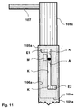
- FIG. 11 shows an enlarged detailed view of part of the guide sleeve 105a 7, wherein in the guide sleeve 105a as a cylindrical shaft 106a formed mandrel is partially inserted; the in the Guide sleeve 105a immersing part of the mandrel 106a is dashed shown.
- the mandrel 106a has one in the area of its upper end one-sided protruding handle 107, which the manual handling of the Dorns or shaft 106a relieved.
- the shaft 106a has an outer surface on its outer surface protruding stop element A on.
- the guide sleeve 105a has in its Wall a slot-like, essentially Z-shaped in plan view Scenery guide K, which is shaped and in which Stop element A, acting as a sliding block, engages so that the Travel of the shaft 106a in the longitudinal direction of the guide sleeve 105a the interaction of the link guide K and the stop element A is limited. Because the edge of the sliding guide K is closed Has curve and not e.g. in the upper edge of the guide sleeve 105a merges, the shaft 106a is due to the interaction of the Guide guide K of the stop element A not out of the guide sleeve 105a removable and therefore advantageously not lost.
- the link guide K runs in the area of the middle line of the Z in Longitudinal direction of the guide sleeve 105a. In its lower end area E2 The link guide K runs transversely to the longitudinal direction of the guide sleeve 105a, thereby forming the bottom line of the Z so that the shaft 106a opposes a method of the same can be locked in the longitudinal direction of the guide sleeve 105 is by the stop element A with the lower end portion E2 Link guide K is engaged.
- the link guide K In its upper end region E1, the link guide K also runs transversely run to the longitudinal direction of the guide sleeve 105a, whereby the onere line of the Z is formed, so that the shaft 106a against a method of the same in Longitudinal direction of the guide sleeve 105a can be locked by the Stop element A with the upper end region E1 of the link guide K in Intervention.
- the backdrop guide K and what engages in it Stop element A thus form a locking mechanism A, K, which in two different positions of the shaft 106a can be activated, namely at maximum of shaft 106a pulled out of the guide sleeve 105a and at maximum shaft 106a inserted into the guide sleeve 105a.
- the shaft 106a has on it Jacket surface a marker M, which in the guide sleeve 105a inserted shaft 106a is only visible from the outside if that Stop element A with the lower end region E2 of the link guide K in Intervention.
- This is done according to the embodiment of FIG. 11 achieved that the link guide K, when the stop element A with the lower end region E2 of the link guide K is engaged as Viewing window for marker M works.
- the marker M In the position of the The shaft 106a opposite the guide sleeve 105a is the marker M through the Guide sleeve 105a covered and therefore shown in dashed or dotted lines.
- the marker can e.g. by luminescent paint or by a light source, e.g. Led, be educated. Its visibility signals that the shaft 106a in is maximally locked in the inserted position in the guide sleeve 105a.
- the other guide sleeve 105b, not shown in FIG. 11, of the device of FIG 7 and the mandrel 106b inserted therein are with the guide sleeve 105a and the mandrel 106a of FIG. 11 are identical.
- the object of the invention is in particular for lifting and pivoting suitable for heavy objects into which holes can be drilled, especially for lifting wooden panels, wooden beams or wide-stack elements, these are combined into a flat element individual woods.
- the device is advantageously attached to the device alone Top of the object to be lifted.
- the device is attached Can be carried out with little effort and effort and is also again solvable.
- the leading figure is Fig. 5.
Landscapes
- Engineering & Computer Science (AREA)
- Mechanical Engineering (AREA)
- Load-Engaging Elements For Cranes (AREA)
- Conveying And Assembling Of Building Elements In Situ (AREA)
- Types And Forms Of Lifts (AREA)
Abstract
Description
- im Bereich der Enden des Querholmes je eine schräg verlaufende Führungshülse angeordnet ist, deren Längsachsen sich unterhalb oder oberhalb des Querholmes in einem Bereich kreuzen, dessen senkrechte Projektion auf den Querholm zwischen den Angriffspunkten liegt, und
- in die Führungshülsen Dorne in lösbarer Weise steckbar sind, welche
- nach dem Einstecken die Führungshülsen nach unterhalb des Querholmes überragen und in Bohrungen einzugreifen imstande sind, welche in Fortsetzung der Führungshülsen schräg in den Gegenstand gebohrt worden sind,
- und imstande sind, eine über die Zugelemente an dem Querholm angreifende Hebekraft mittels Formschluss über die Wandungen der Bohrungen in den Gegenstand einzuleiten.
- Fig. 1
- eine schematische Seitenansicht einer bevorzugten Ausführungsform einer erfindungsgemäßen Vorrichtung, die auf einen zu hebenden Gegenstand aufgesetzt ist,
- Fig.2
- eine Querschnittsansicht einer Hülse mit Lastöse und einem Balken, welcher durch die Hülse verläuft, gemäß einer Ausführungsform der Erfindung, und
- Fig.3
- den äußeren Endbereich des Balkens von Fig. 2 mit der Hülse und einer Führungshülse mit Auflageplatte,
- Fig.4
- eine weitere Ausführungsform der Erfindung, mit verschiebbaren Sperrelementen, welche sich in Freigabestellung befinden,
- Fig.5
- die Vorrichtung von Fig. 4, wobei sich die Sperrelemente in Sperrstellung befinden,
- Fig. 6
- eine schematische Seitenansicht einer weiteren Ausführungsform einer erfindungsgemäßen Vorrichtung,
- Fig.7
- eine perspektivische Ansicht einer weiteren Ausführungsform einer erfindungsgemäßen Vorrichtung,
- Fig. 8
- ein Hebegerät mit zwei der Vorrichtungen von Fig.6, welche mittels einer Traverse gekoppelt sind, in einer ersten bevorzugten räumlichen Anordnung,
- Fig.9
- das Hebegerät von Fig. 8 in einer zweiten bevorzugten räumlichen Anordnung,
- Fig. 10
- eine Bohrschablone zur Unterstützung der Herstellung der Bohrungen in dem Gegenstand, welcher mit einer erfindungsgemäßen Vorrichtung gehoben werden soll, und
- Fig. 11
- eine vergrößerte Detailansicht eines Teils einer Führungshülse der Vorrichtung von Fig. 7 mit einer im wesentlichen Z-förmigen Führungskulisse.
- 1,101,101'
- Querholm
- 1a,1a',1b
- Balken
- 1c,1c'
- Längsachse von 1,1a'
- 1d
- Stange
- 1e
- Verbindungsstab
- 2,102
- Verbindungsbrücken
- 3a, 3b
- Zugstäbe
- 5a,5a',5b,105a,105b
- Führungshülsen
- 6a, 6b
- Dorne
- 7,107
- Handgriffe
- 8,108
- Aufhängeelemente
- 9
- Seil
- 11a, 11b
- untere Gelenkbolzen
- 12a, 12b
- obere Gelenkbolzen
- 14
- zu hebender Gegenstand
- 15
- Bohrung in 14
- 20a, 20b,120a,120b
- Reiter
- 20a'
- Hülse
- 21a,21a'21b
- Lastösen
- 22,22',122,222
- Auflageplatten
- 23a,23b
- Querbohrung in 6a,6b
- 24
- Seitenbohrungen in 5a,5b
- 24'
- Seitenbohrungen in 5a'
- 25a,25b
- Splintbolzen
- 26a,26a'26b
- Anschläge
- 27
- Bohrung in 21a'
- 28
- Verbindungsstück
- 29a, 29b
- Führungen
- 30a, 30b
- Schlitten
- 31 a, 31b
- Sperrelemente
- 106a,106b
- Schafte
- 200
- Bohrschablone
- 201
- Querstange
- 205a,205b
- Bohrschablonenhülsen
- 209
- Markierung
- A
- Anschlagelement
- B, B'
- Fixierbolzen
- E1, E2
- oberer, unterer Endbereich von K
- F
- Fixierhülse
- K
- Kulissenführung
- M
- Marker
- Q
- Querseil
- T
- Traverse
Claims (42)
die Schafte (106a,106b) an ihrer Mantelfläche jeweils ein über dieselbe nach außen überstehendes, als Kulissenstein fungierendes Anschlagelement (A) aufweisen, und die Führungshülsen (105a,105b) in ihrer Wandung jeweils eine rinnen- oder schlitzarigte Kulissenführung (K) aufweisen, welche so geformt ist und in welche je eines der Anschlagelemente (A) so eingreift, dass die Verfahrwege der Schafte (106a,106b) in Längsrichtung der Führungshülsen . (105a) durch das Zusammenwirken der Kulissenführung (K) und dem in diese eingreifenden Anschlagelement (A) jeweils begrenzt sind.
dadurch gekennzeichnet, dass die Querstange (201) im Bereich ihrer auf ihre Längsrichtung bezogenen Mitte eine Markierung (209) zur optischen Kennzeichnung der Mitte der Querstange (201) aufweist
Applications Claiming Priority (2)
| Application Number | Priority Date | Filing Date | Title |
|---|---|---|---|
| DE10235384 | 2002-08-02 | ||
| DE2002135384 DE10235384B4 (de) | 2002-08-02 | 2002-08-02 | Vorrichtung zum Heben von Gegenständen, insbesondere Holzplatten |
Publications (2)
| Publication Number | Publication Date |
|---|---|
| EP1396462A2 true EP1396462A2 (de) | 2004-03-10 |
| EP1396462A3 EP1396462A3 (de) | 2004-07-07 |
Family
ID=30469364
Family Applications (1)
| Application Number | Title | Priority Date | Filing Date |
|---|---|---|---|
| EP03017724A Withdrawn EP1396462A3 (de) | 2002-08-02 | 2003-08-04 | Vorrichtung zum Heben von Gegenständen, insbesondere Holzplatten |
Country Status (2)
| Country | Link |
|---|---|
| EP (1) | EP1396462A3 (de) |
| DE (2) | DE10235384B4 (de) |
Cited By (12)
| Publication number | Priority date | Publication date | Assignee | Title |
|---|---|---|---|---|
| WO2008101490A1 (de) * | 2007-02-22 | 2008-08-28 | Hayrettin Dilsiz | Hebeeinrichtung |
| LT5548B (lt) | 2007-05-22 | 2009-02-25 | Akso-Haus OÜ | Pakėlimo sistema |
| CN110106954A (zh) * | 2019-04-23 | 2019-08-09 | 中宇厨卫股份有限公司 | 一种防踩踏侧滑的两用型马桶 |
| CN111470410A (zh) * | 2020-05-29 | 2020-07-31 | 无锡中车新能源汽车有限公司 | 一种可调式车壳运输吊架 |
| WO2020223128A1 (en) * | 2019-05-01 | 2020-11-05 | Miller Dowel Company | Transport apparatus for assembly component and method of using transport apparatus |
| CN112079242A (zh) * | 2020-10-23 | 2020-12-15 | 常州市西硕金属制品有限公司 | 长条钢结构件吊装用装置 |
| US10935064B2 (en) | 2019-04-19 | 2021-03-02 | Miller Dowel Company | Dowel with directional expanding portion and wall system including directional dowel |
| CN114439507A (zh) * | 2021-12-22 | 2022-05-06 | 中铁二十五局集团第二工程有限公司 | 一种穿越富水断层构造带的隧道初期支护施工方法 |
| CN114751287A (zh) * | 2022-03-17 | 2022-07-15 | 中交第二航务工程局有限公司 | 一种带挂式模块化横移单元的节段梁自动化吊具 |
| US11519166B2 (en) | 2019-06-24 | 2022-12-06 | Miller Dowel Company | Guidance apparatus for assembly of construction panels |
| US11846096B2 (en) | 2020-01-27 | 2023-12-19 | Miller Dowel Company | Construction using bundled tube and threaded stepped dowels |
| CN119735085A (zh) * | 2024-12-26 | 2025-04-01 | 中交一公局集团有限公司 | 一种t梁预制用辅助吊梁装置 |
Families Citing this family (4)
| Publication number | Priority date | Publication date | Assignee | Title |
|---|---|---|---|---|
| DE102019104843B4 (de) * | 2019-02-26 | 2022-12-29 | Jens Rosanowski | Montagelehre für Fahrdrahtaufhängungen sowie ein Verfahren für deren Verwendung |
| DE102019111104A1 (de) * | 2019-04-30 | 2020-11-05 | Achim Franke | Hebeklemme |
| CN111689386B (zh) * | 2020-07-02 | 2025-09-23 | 武汉安振岩土工程有限公司 | 异形建筑构件专用辅助起吊装置及其起吊方法 |
| CN118684111B (zh) * | 2024-08-27 | 2024-11-12 | 河南斓霞建筑工程有限公司 | 一种公路路面摊铺施工吊装设备 |
Family Cites Families (7)
| Publication number | Priority date | Publication date | Assignee | Title |
|---|---|---|---|---|
| US1366746A (en) * | 1920-06-22 | 1921-01-25 | Pohl John | Grapple |
| DE613893C (de) * | 1934-03-21 | 1935-05-25 | Oswald Winkler | Greifvorrichtung mit an Drehbolzen gelagerten Fingern, die in ausgearbeitete OEffnungen des zu hebenden Steines hineinfassen |
| DE1803961A1 (de) * | 1968-10-18 | 1970-06-11 | Hans Tax | Containererfassungsrahmen |
| DE2160575A1 (de) * | 1971-12-07 | 1973-06-14 | Hebel Gasbetonwerk Gmbh | Hebevorrichtung fuer koerper |
| DE3743832A1 (de) * | 1987-12-23 | 1989-07-13 | Kasamentbau Gmbh & Co | Vorrichtung zum versetzen von vorzugsweise aus einer mehrzahl von einzelelementen zusammengesetzten wandelementen |
| DE4229216A1 (de) * | 1991-09-04 | 1993-03-11 | Heinz Schmidt | Vertikalgreifer mit verriegelung |
| DE19962127C2 (de) * | 1999-12-21 | 2002-02-14 | Inholz Gbm | Vorrichtung zum Heben von Gegenständen |
-
2002
- 2002-08-02 DE DE2002135384 patent/DE10235384B4/de not_active Expired - Fee Related
-
2003
- 2003-08-04 EP EP03017724A patent/EP1396462A3/de not_active Withdrawn
- 2003-08-04 DE DE20312024U patent/DE20312024U1/de not_active Expired - Lifetime
Cited By (15)
| Publication number | Priority date | Publication date | Assignee | Title |
|---|---|---|---|---|
| US8113556B2 (en) | 2007-02-22 | 2012-02-14 | Hayrettin Dilsiz | Lifting device |
| WO2008101490A1 (de) * | 2007-02-22 | 2008-08-28 | Hayrettin Dilsiz | Hebeeinrichtung |
| LT5548B (lt) | 2007-05-22 | 2009-02-25 | Akso-Haus OÜ | Pakėlimo sistema |
| US10935064B2 (en) | 2019-04-19 | 2021-03-02 | Miller Dowel Company | Dowel with directional expanding portion and wall system including directional dowel |
| CN110106954A (zh) * | 2019-04-23 | 2019-08-09 | 中宇厨卫股份有限公司 | 一种防踩踏侧滑的两用型马桶 |
| WO2020223128A1 (en) * | 2019-05-01 | 2020-11-05 | Miller Dowel Company | Transport apparatus for assembly component and method of using transport apparatus |
| US11174133B2 (en) | 2019-05-01 | 2021-11-16 | Miller Dowel Company | Transport apparatus for assembly component and method of using transport apparatus |
| EP3962850A4 (de) * | 2019-05-01 | 2022-07-06 | Miller Dowel Company | Transportvorrichtung für ein bauteil und verfahren zur verwendung der transportvorrichtung |
| US11519166B2 (en) | 2019-06-24 | 2022-12-06 | Miller Dowel Company | Guidance apparatus for assembly of construction panels |
| US11846096B2 (en) | 2020-01-27 | 2023-12-19 | Miller Dowel Company | Construction using bundled tube and threaded stepped dowels |
| CN111470410A (zh) * | 2020-05-29 | 2020-07-31 | 无锡中车新能源汽车有限公司 | 一种可调式车壳运输吊架 |
| CN112079242A (zh) * | 2020-10-23 | 2020-12-15 | 常州市西硕金属制品有限公司 | 长条钢结构件吊装用装置 |
| CN114439507A (zh) * | 2021-12-22 | 2022-05-06 | 中铁二十五局集团第二工程有限公司 | 一种穿越富水断层构造带的隧道初期支护施工方法 |
| CN114751287A (zh) * | 2022-03-17 | 2022-07-15 | 中交第二航务工程局有限公司 | 一种带挂式模块化横移单元的节段梁自动化吊具 |
| CN119735085A (zh) * | 2024-12-26 | 2025-04-01 | 中交一公局集团有限公司 | 一种t梁预制用辅助吊梁装置 |
Also Published As
| Publication number | Publication date |
|---|---|
| DE20312024U1 (de) | 2004-02-19 |
| DE10235384A1 (de) | 2004-02-19 |
| EP1396462A3 (de) | 2004-07-07 |
| DE10235384B4 (de) | 2009-10-01 |
Similar Documents
| Publication | Publication Date | Title |
|---|---|---|
| EP1396462A2 (de) | Vorrichtung zum Heben von Gegenständen, insbesondere Holzplatten | |
| DE69622382T2 (de) | Hebevorrichtung zum heben von platten, bretten oder blech | |
| DE1926293B2 (de) | Abstelleinrichtung zum senkrechten lagern von bohrrohr- und schwerstangenzuegen | |
| DE69012875T2 (de) | Rettungsgestell. | |
| EP0034819B1 (de) | Versetzbares Gerüst | |
| EP4047157B1 (de) | Verfahren und vorrichtung zum herstellen einer deckenschalung | |
| EP1020395A2 (de) | Klemmgreifer für von oben zu greifende Lasten | |
| DE102008023670B3 (de) | Montagehilfe und Verfahren zum Aufbau der Montagehilfe | |
| EP1939132A2 (de) | Fernbetätigbarer Lastbügel oder -haken | |
| DE2049211C3 (de) | Greifvorrichtung für Bauteile | |
| EP1630301A1 (de) | Verfahren und Vorrichtung zur Bodenbearbeitung | |
| EP1063368B1 (de) | Arbeitsbühne | |
| DE1481800B1 (de) | Hebeklaue | |
| DE2713485B2 (de) | ||
| DE102015107900B4 (de) | Versetzzange | |
| DE19962127C2 (de) | Vorrichtung zum Heben von Gegenständen | |
| EP3246202B1 (de) | Zurranker | |
| EP0947461A2 (de) | Vorrichtung zum Transportieren von Bauelementen | |
| DE2244585A1 (de) | Knickausleger zum anheben und transportieren von lasten, insbesondere fuer einen kran | |
| DE3605045A1 (de) | Vorrichtung mit einem haltearm zum halten einer an einem gebaeude herabhaengenden last | |
| DE10227864B4 (de) | Greiftraverse zum Greifen von Werksteinen | |
| DE19721635A1 (de) | Vorrichtung zum Ziehen einer Rohrtour | |
| EP0723927B1 (de) | Anhängevorrichtung zum Anhängen wenigstens einer Schaltafel an ein Hebezeug | |
| AT523664B1 (de) | Transporthaken | |
| AT413531B (de) | Anordnung für das heben und transportieren von grossformatigen, insbesondere plattenartigen objekten |
Legal Events
| Date | Code | Title | Description |
|---|---|---|---|
| PUAI | Public reference made under article 153(3) epc to a published international application that has entered the european phase |
Free format text: ORIGINAL CODE: 0009012 |
|
| AK | Designated contracting states |
Kind code of ref document: A2 Designated state(s): AT BE BG CH CY CZ DE DK EE ES FI FR GB GR HU IE IT LI LU MC NL PT RO SE SI SK TR |
|
| AX | Request for extension of the european patent |
Extension state: AL LT LV MK |
|
| PUAL | Search report despatched |
Free format text: ORIGINAL CODE: 0009013 |
|
| AK | Designated contracting states |
Kind code of ref document: A3 Designated state(s): AT BE BG CH CY CZ DE DK EE ES FI FR GB GR HU IE IT LI LU MC NL PT RO SE SI SK TR |
|
| AX | Request for extension of the european patent |
Extension state: AL LT LV MK |
|
| AKX | Designation fees paid | ||
| REG | Reference to a national code |
Ref country code: DE Ref legal event code: 8566 |
|
| STAA | Information on the status of an ep patent application or granted ep patent |
Free format text: STATUS: THE APPLICATION IS DEEMED TO BE WITHDRAWN |
|
| 18D | Application deemed to be withdrawn |
Effective date: 20050108 |