EP1396584A2 - Dispositif d'assemblage pour barrières routières mobiles - Google Patents
Dispositif d'assemblage pour barrières routières mobiles Download PDFInfo
- Publication number
- EP1396584A2 EP1396584A2 EP03425569A EP03425569A EP1396584A2 EP 1396584 A2 EP1396584 A2 EP 1396584A2 EP 03425569 A EP03425569 A EP 03425569A EP 03425569 A EP03425569 A EP 03425569A EP 1396584 A2 EP1396584 A2 EP 1396584A2
- Authority
- EP
- European Patent Office
- Prior art keywords
- connection group
- group according
- joints
- barriers
- lock bolt
- Prior art date
- Legal status (The legal status is an assumption and is not a legal conclusion. Google has not performed a legal analysis and makes no representation as to the accuracy of the status listed.)
- Withdrawn
Links
Images

Classifications
-
- E—FIXED CONSTRUCTIONS
- E01—CONSTRUCTION OF ROADS, RAILWAYS, OR BRIDGES
- E01F—ADDITIONAL WORK, SUCH AS EQUIPPING ROADS OR THE CONSTRUCTION OF PLATFORMS, HELICOPTER LANDING STAGES, SIGNS, SNOW FENCES, OR THE LIKE
- E01F13/00—Arrangements for obstructing or restricting traffic, e.g. gates, barricades ; Preventing passage of vehicles of selected category or dimensions
- E01F13/02—Arrangements for obstructing or restricting traffic, e.g. gates, barricades ; Preventing passage of vehicles of selected category or dimensions free-standing; portable, e.g. for guarding open manholes ; Portable signs or signals specially adapted for fitting to portable barriers
- E01F13/022—Pedestrian barriers; Barriers for channelling or controlling crowds
-
- Y—GENERAL TAGGING OF NEW TECHNOLOGICAL DEVELOPMENTS; GENERAL TAGGING OF CROSS-SECTIONAL TECHNOLOGIES SPANNING OVER SEVERAL SECTIONS OF THE IPC; TECHNICAL SUBJECTS COVERED BY FORMER USPC CROSS-REFERENCE ART COLLECTIONS [XRACs] AND DIGESTS
- Y10—TECHNICAL SUBJECTS COVERED BY FORMER USPC
- Y10T—TECHNICAL SUBJECTS COVERED BY FORMER US CLASSIFICATION
- Y10T403/00—Joints and connections
- Y10T403/32—Articulated members
Definitions
- the present invention relates to a connection group for movable road barriers.
- the barriers usually made of metal, generally have a structure consisting of a base from which there extend two lateral upright members supporting a panel, which may have various shapes and dimensions, bearing inscriptions and/or two-coloured diagonal bands.
- the barriers When an area is to be fenced off, the barriers are placed in line, each adjacent to the next, and joined together with the help of connecting means consisting, as a general rule, of a pair of substantially square hooks that extend in the plane of the barrier from one of the two lateral uprights for engaging with corresponding tubular appendices projecting from the other lateral upright of the adjacent barrier.
- the condition that makes it possible to effect the connection is that the adjacent upright members of the barriers to be connected should be substantially coplanar and parallel. If, for example, the two barriers are not coplanar or if their adjacent uprights tend to converge, this will negatively affect the possibility of getting the hooks to engage with their respective tubular appendices and, as a general rule, continuity of the barrier line is assured by resorting to improvised solutions for connecting the individual barrier elements or tolerating their being in precarious equilibrium and in incomplete contact with the ground. It should further be noted that the barrier connection systems that have so far been employed do not provide for locking the connection, and it is therefore possible for the barriers to be readily separated even by unauthorized persons.
- Another object of the present invention is to provide a connection group for connecting movable road barriers that will make it possible to lock the connection after it has been made, thereby preventing any unauthorized opening of the barrier line.
- connection group for connecting road barriers in accordance with the present invention, which has the feature of comprising a pair of jawed joints that can be attached to the respective uprights of two adjacent barriers and connected to each other in an articulated manner in order to compensate a possible lack of coplanarity and/or parallelism of the uprights due to the conformation of the ground on which the barriers are erected.
- connection between the two joints is made by means of an elastic articulation, preferably consisting of a helical spring that has its respective ends connected to said joints.
- connection group for connecting movable road barriers in accordance with the present invention will be brought out more clearly by the following description of a particular embodiment thereof, which is given by way of example and is not to be considered limitative in any way, the description making reference to the attached drawings, of which:
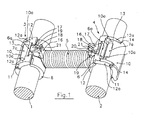
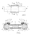
- the reference numbers 1 and 2 indicate, respectively, the two upright members of two conventional movable road barriers, not completely shown, arranged in line and next to each other.
- the reference numbers 3 and 4 are used to generically indicate a pair of identically shaped joints of the jawed type connected to each other by means of a helicoidal spring 5 that has its respective ends connected to the joints 3 and 4.
- joints 3 and 4 are characterized by the same components, which in the drawings will be indicated by means of the same reference numbers.
- Each of the joints 3 and 4 consists of an inner jaw 6 and an outer jaw 7 pivotably connected to each other at their respective ends by means of a pin 8.
- Both the inner jaw 6 and outer jaw 7 has a semi-annular profile with a semi-circular internal section, but it is quite obvious that the internal section could be of any shape whatsoever, always provided that it matches the shape of uprights 1 and 2.
- Outer jaw 7 has its other end pivotably connected by means of a pin 9 to an operating lever 10 that, in its turn, is pivotably connected by means of a pin 11 to two arms 12a of a crosspiece 12. Pin 11 that connects the operating lever 10 to the crosspiece 12 extends transversely at a position intermediate between pin 9, which connects outer jaw 7 to operating lever 10, and the free end of said operating lever 10.
- the operating lever 10 Transversely and in a position intermediate between pin 9 that connects outer jaw 7 to the operating lever, the operating lever 10 extends above outer jaw 7 and is provided with a pair of arms 10a defining a recess for arranging the end 7a of outer jaw 7. End 7a, in its turn, is provided with a seating, not shown, for pin 9.
- Operating lever 10 is also provided with two identical recesses 14 in which there are accommodated arms 12a of crosspiece 12.
- the end of inner jaw 6 opposite the end that is articulated to outer jaw 7 has a substantially hook-shaped appendix 6a, open at its upper side, with which a correspondingly shaped portion of crosspiece 12 can engage to close joint 3 (or 4).
- Spring 5 is connected to joints 3 and 4 by virtue of the fact that its terminal coils are wound around respective sleeves 15 that extend radially from inner jaws 6. With a view to assuring a more stable connection between the coils of spring 5 and sleeves 15, the lateral surface of the sleeves is provided with a helicoidal groove 15a (which can be seen in Figures 3 and 5) acting as a seating for the coils of spring 5.
- inner jaw 6 is provided with a small turret 16 extending at right angles to the respective sleeve 15 on the same side as the hook-shaped appendix 6a.
- a seating 16a that engages with stem 17a of a lock bolt 17 that, on being rotated about its own axis, can be made to abut against crosspiece 12 when it is engaged in the hook-shaped appendix, thus preventing the crosspiece from becoming disengaged and therefore the opening of the joint.
- lock bolt 17 With a view to permitting lock bolt 17 to be rotated, it is provided with a cavity 18 along the axis of its stem 17a.
- Cavity 18 is appropriately shaped to enable it to accommodate a correspondingly shaped key tool by means of which lock bolt 17 can be rotated.
- a pin 22 arranged in a transverse groove 16b of turret 16 and projecting into a corresponding annular groove 17b of stem 17a.
- crosspiece 12 can be advantageously provided with a wedge-shaped corner 23 that, in the closed condition of the joint, comes to engage with a corresponding recess 24 provided on inner face of the hook-shaped appendix 6a.
- crosspiece 12 abuts at one side against recess 24 and on the other side against lock bolt 17 that exerts a moderate force on it.
- Crosspiece 12 is therefore locked against hook-shaped appendix 6a without any clearance whatsoever, thus assuring the perfect stability of the connection between the joint and the relevant upright.
- connection group in accordance with the present invention can also be advantageously employed to provide a transverse stiffening of the barrier line by doubling some of the barrier members with corresponding parallel barriers.
- connection group according to the invention which is made rigid, i.e. no longer articulated, by insertion, within spring 5 and coaxially thereto, of a rigid bar, not shown, the ends of which are engaged within sleeves 15
- connection group for connecting movable road barriers in accordance with the present invention without departing from the scope of the invention as set forth in the appended claims.
Landscapes
- Engineering & Computer Science (AREA)
- Architecture (AREA)
- Civil Engineering (AREA)
- Structural Engineering (AREA)
- Refuge Islands, Traffic Blockers, Or Guard Fence (AREA)
- Road Signs Or Road Markings (AREA)
Applications Claiming Priority (2)
| Application Number | Priority Date | Filing Date | Title |
|---|---|---|---|
| IT000165A ITFI20020165A1 (it) | 2002-09-09 | 2002-09-09 | Elemento di collegamento per transenne stradali |
| ITFI20020165 | 2002-09-09 |
Publications (2)
| Publication Number | Publication Date |
|---|---|
| EP1396584A2 true EP1396584A2 (fr) | 2004-03-10 |
| EP1396584A3 EP1396584A3 (fr) | 2004-08-11 |
Family
ID=31503935
Family Applications (1)
| Application Number | Title | Priority Date | Filing Date |
|---|---|---|---|
| EP03425569A Withdrawn EP1396584A3 (fr) | 2002-09-09 | 2003-09-03 | Dispositif d'assemblage pour barrières routières mobiles |
Country Status (4)
| Country | Link |
|---|---|
| US (1) | US20040062594A1 (fr) |
| EP (1) | EP1396584A3 (fr) |
| JP (1) | JP2004100448A (fr) |
| IT (1) | ITFI20020165A1 (fr) |
Families Citing this family (2)
| Publication number | Priority date | Publication date | Assignee | Title |
|---|---|---|---|---|
| GB2601255A (en) * | 2017-07-19 | 2022-05-25 | Joseph Mark | A locking device |
| GB2624165B (en) | 2022-11-04 | 2025-03-26 | Plant Jonathan | A clamp for coupling temporary fencing panels |
Family Cites Families (24)
| Publication number | Priority date | Publication date | Assignee | Title |
|---|---|---|---|---|
| US530456A (en) * | 1894-12-04 | Padlock | ||
| US2193747A (en) * | 1938-11-16 | 1940-03-12 | Thomas S Thompson | Signal |
| US2539229A (en) * | 1947-12-16 | 1951-01-23 | Alberta Lemieux | Cable spring handle connection |
| US2849777A (en) * | 1956-04-18 | 1958-09-02 | Slater N Co Ltd | Mounting clamp for torsional dampers |
| DE1047893B (de) * | 1957-09-10 | 1958-12-31 | Bayerische Schrauben Und Feder | Feldabstandhalter fuer elektrische Buendelleiter |
| US2949324A (en) * | 1959-03-17 | 1960-08-16 | Birge Homer | Flexible sign post |
| US3121770A (en) * | 1960-08-17 | 1964-02-18 | Aluminum Co Of America | Parallel bundle conductor spacers with vibration dampener |
| US3260789A (en) * | 1963-12-20 | 1966-07-12 | Aubrey T Edwards | Bundled conductor spacer damper |
| US3806627A (en) * | 1969-09-16 | 1974-04-23 | Chance Co | Spacer-damper for bundle conductors |
| US3659034A (en) * | 1970-09-28 | 1972-04-25 | Aluminum Co Of America | Self-damping bundle conductor spacer |
| US3777046A (en) * | 1972-08-14 | 1973-12-04 | Gould Inc | Elastomeric spacer and/or damper for electrical conductors |
| DE2834338C2 (de) * | 1978-08-04 | 1985-03-28 | Heinrich Wunder GmbH & Co KG, 8060 Dachau | Diebstahlsicherung für einen Segelmast |
| US4299507A (en) * | 1979-01-04 | 1981-11-10 | Collins Ii Josiah W | Two-piece controlled motion hinge coupler joint |
| US4332563A (en) * | 1981-02-17 | 1982-06-01 | Ipco Corporation | Flexible dental retaining splint |
| US5074704A (en) * | 1986-01-02 | 1991-12-24 | Mckay Alan R | Roadway barrier system |
| US4949559A (en) * | 1988-05-26 | 1990-08-21 | Meyer Plastics, Inc. | Article lock |
| US5058863A (en) * | 1988-09-15 | 1991-10-22 | Maffet Harold C | Panel apparatus and elements for securing a plurality of panels together |
| US4953819A (en) * | 1989-11-15 | 1990-09-04 | Davis Dale C | Adjustable support clamp apparatus and method |
| US5201498A (en) * | 1992-01-21 | 1993-04-13 | Akins Edward A | Flexible fencing system |
| US5297570A (en) * | 1992-08-24 | 1994-03-29 | Conner Warren D | Golf bag umbrella |
| US5433549A (en) * | 1993-09-07 | 1995-07-18 | Thomas H. McGaffigan | Flexible tie strut |
| US5439311A (en) * | 1993-12-17 | 1995-08-08 | Flexstake, Inc. | Bendable marker with ribbed sleeve |
| US5384930A (en) * | 1994-03-10 | 1995-01-31 | Uno; Thomas A. | Push brooms with flexible couplings in the handles |
| US6152081A (en) * | 1999-02-16 | 2000-11-28 | Baker; Michael D. | Quasistable dog kennel |
-
2002
- 2002-09-09 IT IT000165A patent/ITFI20020165A1/it unknown
-
2003
- 2003-09-03 EP EP03425569A patent/EP1396584A3/fr not_active Withdrawn
- 2003-09-08 US US10/658,156 patent/US20040062594A1/en not_active Abandoned
- 2003-09-08 JP JP2003315135A patent/JP2004100448A/ja active Pending
Also Published As
| Publication number | Publication date |
|---|---|
| EP1396584A3 (fr) | 2004-08-11 |
| JP2004100448A (ja) | 2004-04-02 |
| ITFI20020165A1 (it) | 2004-03-10 |
| US20040062594A1 (en) | 2004-04-01 |
Similar Documents
| Publication | Publication Date | Title |
|---|---|---|
| US8864108B2 (en) | Barrier section connection system | |
| US5150885A (en) | Picket fence assembly | |
| US20090133191A1 (en) | Center support for bed frame, bed frame and assembly method | |
| US11608650B2 (en) | Railing system | |
| DE4310027C1 (de) | Seitenstrebe für einen Unterlenker eines Traktors | |
| US6318217B1 (en) | Through-bolt gripping pliers with adjustable opening width | |
| US7182000B1 (en) | Adaptable hand tool | |
| DE3514562A1 (de) | Balken-klemmvorrichtung | |
| EP1396584A2 (fr) | Dispositif d'assemblage pour barrières routières mobiles | |
| JPH0325136A (ja) | 再配置可能な壁の連続パネルを解除可能に固定する相互接続構造 | |
| US7591208B2 (en) | Multi-coupling adjustable tools | |
| DE10160767C2 (de) | Kettenschloß | |
| US20030127638A1 (en) | Ranch fence | |
| NL2012022C2 (nl) | Koppeling voor een bouwsteiger alsmede borgmiddelen en een borgbeugel voor toepassing daarin. | |
| AU2004270928B2 (en) | Anti-tamper device | |
| US4687238A (en) | Gate lock | |
| US20040079930A1 (en) | Extending barrier on rollers with manually extensible and retractable pivoting elements | |
| EP0118005A1 (fr) | Interrupteur multipolaire de puissance à haute tension | |
| JP6101024B2 (ja) | 連結式バリケードフェンス | |
| CN210830712U (zh) | 一种简易的标准闸阀门锁 | |
| GB2601255A (en) | A locking device | |
| DE3313869C2 (fr) | ||
| JP3007348B1 (ja) | 鎖装架用支柱 | |
| DE19618451B4 (de) | Sicherung gegen unbefugtes Lösen für eine elektrische Steckverbindung | |
| JP3016427U (ja) | リンク型ロック装置 |
Legal Events
| Date | Code | Title | Description |
|---|---|---|---|
| PUAI | Public reference made under article 153(3) epc to a published international application that has entered the european phase |
Free format text: ORIGINAL CODE: 0009012 |
|
| AK | Designated contracting states |
Kind code of ref document: A2 Designated state(s): AT BE BG CH CY CZ DE DK EE ES FI FR GB GR HU IE IT LI LU MC NL PT RO SE SI SK TR |
|
| AX | Request for extension of the european patent |
Extension state: AL LT LV MK |
|
| PUAL | Search report despatched |
Free format text: ORIGINAL CODE: 0009013 |
|
| AK | Designated contracting states |
Kind code of ref document: A3 Designated state(s): AT BE BG CH CY CZ DE DK EE ES FI FR GB GR HU IE IT LI LU MC NL PT RO SE SI SK TR |
|
| AX | Request for extension of the european patent |
Extension state: AL LT LV MK |
|
| 17P | Request for examination filed |
Effective date: 20041115 |
|
| AKX | Designation fees paid |
Designated state(s): AT BE BG CH CY CZ DE DK EE ES FI FR GB GR HU IE IT LI LU MC NL PT RO SE SI SK TR |
|
| STAA | Information on the status of an ep patent application or granted ep patent |
Free format text: STATUS: THE APPLICATION IS DEEMED TO BE WITHDRAWN |
|
| 18D | Application deemed to be withdrawn |
Effective date: 20070402 |