EP1396607A2 - Procédé de mesure de caractéristiques de formation à l'aide d'un test de formation à durée limitée - Google Patents
Procédé de mesure de caractéristiques de formation à l'aide d'un test de formation à durée limitée Download PDFInfo
- Publication number
- EP1396607A2 EP1396607A2 EP03255458A EP03255458A EP1396607A2 EP 1396607 A2 EP1396607 A2 EP 1396607A2 EP 03255458 A EP03255458 A EP 03255458A EP 03255458 A EP03255458 A EP 03255458A EP 1396607 A2 EP1396607 A2 EP 1396607A2
- Authority
- EP
- European Patent Office
- Prior art keywords
- pressure
- formation
- pretest
- flowline
- mud
- Prior art date
- Legal status (The legal status is an assumption and is not a legal conclusion. Google has not performed a legal analysis and makes no representation as to the accuracy of the status listed.)
- Granted
Links
Images


Classifications
-
- E—FIXED CONSTRUCTIONS
- E21—EARTH OR ROCK DRILLING; MINING
- E21B—EARTH OR ROCK DRILLING; OBTAINING OIL, GAS, WATER, SOLUBLE OR MELTABLE MATERIALS OR A SLURRY OF MINERALS FROM WELLS
- E21B49/00—Testing the nature of borehole walls; Formation testing; Methods or apparatus for obtaining samples of soil or well fluids, specially adapted to earth drilling or wells
- E21B49/008—Testing the nature of borehole walls; Formation testing; Methods or apparatus for obtaining samples of soil or well fluids, specially adapted to earth drilling or wells by injection test; by analysing pressure variations in an injection or production test, e.g. for estimating the skin factor
-
- E—FIXED CONSTRUCTIONS
- E21—EARTH OR ROCK DRILLING; MINING
- E21B—EARTH OR ROCK DRILLING; OBTAINING OIL, GAS, WATER, SOLUBLE OR MELTABLE MATERIALS OR A SLURRY OF MINERALS FROM WELLS
- E21B49/00—Testing the nature of borehole walls; Formation testing; Methods or apparatus for obtaining samples of soil or well fluids, specially adapted to earth drilling or wells
- E21B49/08—Obtaining fluid samples or testing fluids, in boreholes or wells
- E21B49/10—Obtaining fluid samples or testing fluids, in boreholes or wells using side-wall fluid samplers or testers
Definitions
- the present invention relates generally to the field of oil and gas exploration. More particularly, the invention relates to methods for determining at least one property of a subsurface formation penetrated by a wellbore using a formation tester.
- a borehole is typically drilled from the earth surface to the desired subsurface formation and tests are performed on the formation to determine whether the formation is likely to produce hydrocarbons of commercial value.
- tests performed on subsurface formations involve interrogating penetrated formations to determine whether hydrocarbons are actually present and to assess the amount of producible hydrocarbons therein.
- formation testers are typically lowered into a wellbore by a wireline cable, tubing, drill string, or the like, and may be used to determine various formation characteristics which assist in determining the quality, quantity, and conditions of the hydrocarbons or other fluids located therein.
- Other formation testers may form part of a drilling tool, such as a drill string, for the measurement of formation parameters during the drilling process.
- Formation testers typically comprise slender tools adapted to be lowered into a borehole and positioned at a depth in the borehole adjacent to the subsurface formation for which data is desired. Once positioned in the borehole, these tools are placed in fluid communication with the formation to collect data from the formation. Typically, a probe, snorkel or other device is sealably engaged against the borehole wall to establish such fluid communication.
- Formation testers are typically used to measure downhole parameters, such as wellbore pressures, formation pressures and formation mobilities, among others. They may also be used to collect samples from a formation so that the types of fluid contained in the formation and other fluid properties can be determined. The formation properties determined during a formation test are important factors in determining the commercial value of a well and the manner in which hydrocarbons may be recovered from the well.
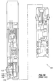
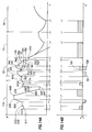
- FIG. 1A the wireline tester 100 is lowered from an oil rig 2 into an open wellbore 3 filled with a fluid commonly referred to in the industry as "mud.”
- the wellbore is lined with a mudcake 4 deposited onto the wall of the wellbore during drilling operations.
- the wellbore penetrates a formation 5.
- Figure 2 depicts a graphical representation of a pressure trace over time measured by the formation tester during a conventional wireline formation testing operation used to determine parameters, such as formation pressure.
- a formation tester 100 is lowered into a wellbore 3 by a wireline cable 6.
- pressure in the flowline 119 in the formation tester may be equalized to the hydrostatic pressure of the fluid in the wellbore by opening an equalization valve (not shown).
- a pressure sensor or gauge 120 is used to measure the hydrostatic pressure of the fluid in the wellbore. The measured pressure at this point is graphically depicted along line 103 in Figure 2.
- the formation tester 100 may then be "set” by anchoring the tester in place with hydraulically actuated pistons; positioning the probe 112 against the sidewall of the wellbore to establish fluid communication with the formation, and closing the equalization valve to isolate the interior of the tool from the well fluids.
- the point at which a seal is made between the probe and the formation and fluid communication is established referred to as the "tool set” point, is graphically depicted at 105 in Figure 2.
- Fluid from the formation 5 is then drawn into the formation tester 100 by retracting a piston 118 in a pretest chamber 114 to create a pressure drop in the flowline 119 below the formation pressure.
- This volume expansion cycle referred to as a "drawdown" cycle, is graphically illustrated along line 107 in Figure 2.
- the shape of the curve and corresponding data generated by the pressure trace may be used to determine various formation characteristics. For example, pressures measured during drawdown (107 in Figure 2) and build-up (113 in Figure 2) may be used to determine formation mobility, that is the ratio of the formation permeability to the formation fluid viscosity.
- formation mobility that is the ratio of the formation permeability to the formation fluid viscosity.
- pressure data collected downhole is typically communicated to the surface electronically via the wireline communication system.
- an operator typically monitors the pressure in flowline 119 at a console and the wireline logging system records the pressure data in real time.
- Data recorded during the drawdown and buildup cycles of the test may be analyzed either at the well site computer in real time or later at a data processing center to determine crucial formation parameters, such as formation fluid pressure, the mud overbalance pressure, ie the difference between the wellbore pressure and the formation pressure, and the mobility of the formation.
- Wireline formation testers allow high data rate communications for real-time monitoring and control of the test and tool through the use of wireline telemetry.
- This type of communication system enables field engineers to evaluate the quality of test measurements as they occur, and, if necessary, to take immediate actions to abort a test procedure and/or adjust the pretest parameters before attempting another measurement. For example, by observing the data as they are collected during the pretest drawdown, an engineer may have the option to change the initial pretest parameters, such as drawdown rate and drawdown volume, to better match them to the formation characteristics before attempting another test.
- Examples of prior art wireline formation testers and/or formation test methods are described, for example, in U.S. Patent Nos. 3,934,468 issued to Brieger; 4,860,581 and 4,936,139 issued to Zimmerman et al.; and 5,969,241 issued to Auzerais. These patents are assigned to the assignee of the present invention.
- Formation testers may also be used during drilling operations.
- one such downhole tool adapted for collecting data from a subsurface formation during drilling operations is disclosed in U.S. Patent No. 6,230,557 B1 issued to Ciglenec et al., which is assigned to the assignee of the present invention.
- a method is desired that enables a formation tester to be used to perform formation test measurements downhole within a specified time period and that may be easily implemented using wireline or drilling tools resulting in minimal intervention from the surface system.
- a method for determining formation parameters using a downhole tool positioned in a wellbore adjacent a subterranean formation comprises the steps of establishing fluid communication with the formation; performing a first pretest to determine an initial estimate of the formation parameters; designing pretest criteria for performing a second pretest based on the initial estimate of the formation parameters; and performing a second pretest according to the designed criteria whereby a refined estimate of the formation parameters are determined.
- a method for determining at least one formation fluid property using a formation tester in a formation penetrated by a borehole includes collecting a first set of data points representing pressures in a pretest chamber of the formation tester as a function of time during a first pretest; determining an estimated formation pressure and an estimated formation fluid mobility from the first set of data points; determining a set of parameters for a second pretest, the set of parameters being determined based on the estimated formation pressure, the estimated formation fluid mobility, and a time remaining for performing the second pretest; performing the second pretest using the set of parameters; collecting a second set of data points representing pressures in the pretest chamber as a function of time during the second pretest; and determining the at least one formation fluid property from the second set of data points.
- a method for determining a termination condition for a drawdown operation using a formation tester in a formation penetrated by a borehole includes setting a probe of the formation tester against a wall of the borehole so that a pretest chamber is in fluid communication with the formation, a drilling fluid in the pretest chamber having a higher pressure than the formation pressure; decompressing the drilling fluid in the pretest chamber by withdrawing a pretest piston at a constant drawdown rate; collecting data points representing fluid pressures in the pretest chamber as a function of time; identifying a range of consecutive data points that fit a line of pressure versus time with a fixed slope, the fixed slope being based on a compressibility of the drilling fluid, the constant drawdown rate, and a volume of the pretest chamber; and terminating the drawdown operation based on a termination criterion after the range of the consecutive data points is identified.
- a method for estimating a formation fluid mobility includes performing a pretest using a formation tester disposed in a formation penetrated by a borehole, the pretest comprising a drawdown phase and a buildup phase; collecting data points representing pressures in a pretest chamber of the formation tester as a function of time during the drawdown phase and the buildup phase; determining an estimated formation pressure from the data points; determining an area bounded by a line passing through the estimated formation pressure and curves interpolating the data points during the drawdown phase and the buildup phase; and estimating the formation fluid mobility from the area, a volume extracted from the formation during the pretest, a radius of the formation testing probe, and a shape factor that accounts for the effect of the borehole on a response of the formation testing probe.
- a method for determining an estimated formation pressure from a drawdown operation using a formation tester in a formation penetrated by a borehole includes setting the formation tester against a wall of the borehole so that a pretest chamber of the formation tester is in fluid communication with the formation, a drilling fluid in the pretest chamber having a higher pressure than the formation pressure; decompressing the drilling fluid in the pretest chamber by withdrawing a pretest piston in the formation tester at a constant drawdown rate; collecting data points representing fluid pressures in the pretest chamber as a function of time; identifying a range of consecutive data points that fit a line of pressure versus time with a fixed slope, the fixed slope being based on a compressibility of the drilling fluid, the constant drawdown rate, and a volume of the pretest chamber; and determining the estimated formation pressure from a first data point after the range of the consecutive data points.
- the invention in another aspect, relates to a method for determining downhole parameters using a downhole tool positioned in a wellbore adjacent a subterranean formation.
- the method includes establishing fluid communication between a pretest chamber in the downhole tool and the formation via a flowline (the flowline has an initial pressure therein), moving a pretest piston positioned in the pretest chamber in a controlled manner to reduce the initial pressure to a drawdown pressure, terminating movement of the piston to permit the drawdown pressure to adjust to a stabilized pressure and repeating the steps until a difference between the stabilized pressure and the initial pressure is substantially smaller than a predetermined pressure drop.
- One or more downhole parameters may then be determined from an analysis of one or more of the pressures.
- An initial estimate of the formation parameters from an analysis of one or more of the pressures and pretest criteria for performing a second pretest based on the initial estimate of the formation parameters may be determined, and a pretest of the formation according to the designed pretest criteria whereby a refined estimate of the formation parameters is determined may be performed.
- the invention in yet another aspect, relates to a method for estimating a formation pressure using a formation tester disposed in a wellbore penetrating a formation.
- the method comprises measuring a first pressure in a flowline that is in fluid communication with the subterranean formation, moving a pretest piston in a controlled manner in a pretest chamber to create a predetermined pressure drop in the flowline, stopping the pretest piston after a selected movement of the pretest piston, allowing the pressure in the flowline to stabilize and repeating the steps until a difference between the stabilized pressure in the flowline and the first pressure in the flowline is substantially smaller than the predetermined pressure drop.
- the formation pressure may then be determined based on a final stabilized pressure in the flowline.
- the invention relates to a method of determining mud compressibility using a downhole tool positioned in a wellbore adjacent a subterranean formation.
- the method includes capturing wellbore fluid in the formation tester (the wellbore fluid is in fluid communication with a pretest chamber having a movable piston therein), selectively moving the piston in the pretest chamber to alter the volume of captured fluid in the downhole tool, measuring the pressure of the captured fluid and estimating mud compressibility from the measured pressure.
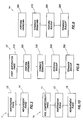
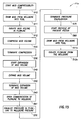
- FIG. 3 An embodiment of the present invention relating to a method 1 for estimating formation properties (e.g. formation pressures and mobilities) is shown in the block diagram of Figure 3. As shown in Figure 3, the method includes an investigation phase 13 and a measurement phase 14.
- formation properties e.g. formation pressures and mobilities
- the method may be practiced with any formation tester known in the art, such as the tester described with respect to Figures 1A and 1B.
- Other formation testers may also be used and/or adapted for embodiments of the invention, such as the wireline formation tester of U.S. Patent No. 4,860,581 and 4,936,139 issued to Zimmerman et al. and the downhole drilling tool of U.S. Patent No. 6,230,557 B1 issued to Ciglenec et al. the entire contents of which are hereby incorporated by reference.
- the module 101 includes a probe 112a, a packer 110a surrounding the probe, and a flow line 119a extending from the probe into the module.
- the flow line 119a extends from the probe 112a to probe isolation valve 121a, and has a pressure gauge 123a.
- a second flow line 103a extends from the probe isolation valve 121a to sample line isolation valve 124a and equalization valve 128a, and has pressure gauge 120a.
- a reversible pretest piston 118a in a pretest chamber 114a also extends from flow line 103a.
- Exit line 126a extends from equalization valve 128a and out to the wellbore and has a pressure gauge 130a.
- Sample flow line 125a extends from sample line isolation valve 124a and through the tool. Fluid sampled in flow line 125a may be captured, flushed, or used for other purposes.
- Probe isolation valve 121 a isolates fluid in flow line 119a from fluid in flow line 103a.
- Sample line isolation valve 124a isolates fluid in flow line 103a from fluid in sample line 125a.
- Equalizing valve 128a isolates fluid in the wellbore from fluid in the tool.
- the pressure gauges 120a and 123a may be used to determine various pressures. For example, by closing valve 121a formation pressure may be read by gauge 123a when the probe is in fluid communication with the formation while minimizing the tool volume connected to the formation.
- equalizing valve 128a open mud may be withdrawn from the wellbore into the tool by means of pretest piston 118a.
- probe isolation valve 121a and sample line isolation valve 124a fluid may be trapped within the tool between these valves and the pretest piston 118a.
- Pressure gauge 130a may be used to monitor the wellbore fluid pressure continuously throughout the operation of the tool and together with pressure gauges 120a and/or 123a may be used to measure directly the pressure drop across the mudcake and to monitor the transmission of wellbore disturbances across the mudcake for later use in correcting the measured sandface pressure for these disturbances.
- pretest piston 118a Among the functions of pretest piston 118a is to withdraw fluid from or inject fluid into the formation or to compress or expand fluid trapped between probe isolation valve 121a, sample line isolation valve 124a and equalizing valve 128a.
- the pretest piston 118a preferably has the capability of being operated at low rates, for example 0.01 cm 3 /sec, and high rates, for example 10 cm 3 /sec, and has the capability of being able to withdraw large volumes in a single stroke, for example 100 cm 3 .
- the pretest piston 118a may be recycled.
- the position of the pretest piston 118a preferably can be continuously monitored and positively controlled and its position can be "locked" when it is at rest.
- the probe 112a may further include a filter valve (not shown) and a filter piston (not shown).
- valves pretest piston and probe
- FIG. 4 depicts a probe type module, it will be appreciated that either a probe tool or a packer tool may be used, perhaps with some modifications. The following description assumes a probe tool is used. However, one skilled in the art would appreciate that similar procedures may be used with packer tools.
- flowline as used herein shall refer to a conduit, cavity or other passage for establishing fluid communication between the formation and the pretest piston and/or for allowing fluid flow there between.
- Other such devices may include, for example, a device in which the probe and the pretest piston are integral.
- An example of such a device is disclosed in U.S. Patent No. 6,230,557 B1 and U.S. Patent Application Serial No. 10/248,782, assigned to the assignee of the present invention.
- the investigation phase 13 relates to obtaining initial estimates of formation parameters, such as formation pressure and formation mobility. These initial estimates may then be used to design the measurement phase 14. If desired and allowed, a measurement phase is then performed according to these parameters to generate a refined estimate of the formation parameters.
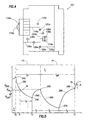
- Figure 5 depicts a corresponding pressure trace illustrating the changes in pressure over time as the method of Figure 3 is performed. It will be appreciated that, while the pressure trace of Figure 5 may be performed by the apparatus of Figure 4, it may also be performed by other downhole tools, such as the tester of Figures 1A and 1B.
- the investigation phase 13 is shown in greater detail in Figure 6.
- the investigation phase comprises initiating the drawdown 310 after the tool is set for duration T i at time t 3 , performing the drawdown 320, terminating the drawdown 330, performing the buildup 340 and terminating the buildup 350.
- the probe 112a is placed in fluid communication with the formation and anchored into place and the interior of the tool is isolated from the wellbore.
- the drawdown 320 is performed by advancing the piston 118a in pretest chamber 114a.
- the pressure will begin to build up in flow line 119a until the buildup 340 is terminated at 350.
- the investigation phase lasts for a duration of time T IP .
- the investigation phase may also be performed as previously described with respect to Figures 1B and 2, the drawdown flow rate and the drawdown termination point being pre-defined before the initiation of the investigation phase.
- the pressure trace of the investigation phase 13 is shown in greater detail in Figure 7.
- Parameters such as formation pressure and formation mobility, may be determined from an analysis of the data derived from the pressure trace of the investigation phase.
- termination point 350 represents a provisional estimate of the formation pressure.
- formation pressures may be estimated more precisely by extrapolating the pressure trend obtained during build up 340 using techniques known by those of skill in the art, the extrapolated pressure corresponding to the pressure that would have been obtained had the buildup been allowed to continue indefinitely. Such procedures may require additional processing to arrive at formation pressure.
- Formation mobility ( K / ⁇ ) 1 may also be determined from the build up phase represented by line 340. Techniques known by those of skill in the art may be used to estimate the formation mobility from the rate of pressure change with time during build up 340. Such procedures may require additional processing to arrive at estimates of the formation mobility.
- the drawdown step 320 of the investigation phase may be analyzed to determine the pressure drop over time to determine various characteristics of the pressure trace.
- a best fit line 32 derived from points along drawdown line 320 is depicted extending from initiation point 310.
- a deviation point 34 may be determined along curve 320 representing the point at which the curve 320 reaches a minimum deviation ⁇ 0 from the best fit line 32.
- the deviation point 34 may be used as an estimate of the "onset of flow", the point at which fluid is delivered from the formation into the tool during the investigation phase drawdown.
- the deviation point 34 may be determined by known techniques, such as the techniques disclosed in U.S. Patent Nos. 5,095,745 and 5,233,866 both issued to Desbrandes, the entire contents of which are hereby incorporated by reference. Debrandes teaches a technique for estimating the formation pressure from the point of deviation from a best fit line created using datapoints from the drawdown phase of the pretest.
- the deviation point may alternatively be determined by testing the most recently acquired point to see if it remains on the linear trend representing the flowline expansion as successive pressure data are acquired. If not, the drawdown may be terminated and the pressure allowed to stabilize.
- the deviation point may also be determined by taking the derivative of the pressure recorded during 320 with respect to time. When the derivative changes (presumably becomes less) by 2-5%, the corresponding point is taken to represent the beginning of flow from the formation. If necessary, to confirm that the deviation from the expansion line represents flow from the formation, further small-volume pretests may be performed.
- deviation point 34 may be determined using other techniques. For example, another technique for determining the deviation point 34 is based on mud compressibility and will be discussed further with respect to Figures 9-11.
- the drawdown is continued beyond the point 34 until some prescribed termination criterion is met. Such criteria may be based on pressure, volume and/or time. Once the criterion has been met, the drawdown is terminated and termination point 330 is reached. It is desirable that the termination point 330 occur at a given pressure P 330 within a given pressure range ⁇ P relative to the deviation pressure P 34 corresponding to deviation point 34 of Figure 7. Alternatively, it may be desirable to terminate drawdown within a given period of time following the determination of the deviation point 34.
- termination may be preset to occur by time t 7 , where the time expended between time t 4 and t 7 is designated as T D and is limited to a maximum duration.
- Another criterion for terminating the pretest is to limit the volume withdrawn from the formation after the point of deviation 34 has been identified. This volume may be determined by the change in volume of the pretest chamber 114a ( Figure 4). The maximum change in volume may be specified as a limiting parameter for the pretest.
- One or more of the limiting criteria, pressure, time and/or volume may be used alone or in combination to determine the termination point 330. If, for example, as in the case of highly permeable formations, a desired criterion, such as a predetermined pressure drop, cannot be met, the duration of the pretest may be further limited by one or more of the other criteria.
- the pressure at which the build up becomes sufficiently stable is often taken as an estimate of the formation pressure.
- the buildup pressure is monitored to provide data for estimating the formation pressure from the progressive stabilization of the buildup pressure.
- the information obtained may be used in designing a measurement phase transient such that a direct measurement of the formation pressure is achieved at the end of build up. The question of how long the investigation phase buildup should be allowed to continue to obtain an initial estimate of the formation pressure remains.
- a set time limit may be used for the duration of the buildup T 1 .
- T 1 may be set at some number, such as 2 to 3 times the time of flow from the formation T 0 .
- Other techniques and criteria may be envisioned.
- termination point 350 depicts the end of the buildup, the end of the investigation phase and/or the beginning of the measurement phase. Certain criteria may be used to determine when termination 350 should occur. A possible approach to determination of termination 350 is to allow the measured pressure to stabilize. To establish a point at which a reasonably accurate estimate of formation pressure at termination point 350 may be made relatively quickly, a procedure for determining criteria for establishing when to terminate may be used.
- one such procedure involves establishing a pressure increment beginning at the termination of drawdown point 330.
- a pressure increment could be a large multiple of the pressure gauge resolution, or a multiple of the pressure gauge noise.
- buildup data are acquired successive pressure points will fall within one such interval.
- the highest pressure data point within each pressure increment is chosen and differences are constructed between the corresponding times to yield the time increments ⁇ t i(n) .
- Buildup is continued until the ratio of two successive time increments is greater than or equal to a predetermined number, such as 2.
- the last recorded pressure point in the last interval at the time this criterion is met is the calculated termination point 350.
- This analysis may be mathematically represented by the following:
- n P is a number with a value equal to or greater than, for example, 4, typically 10 or greater
- ⁇ P is the nominal resolution of the pressure measuring instrument
- ⁇ P is a small multiple, say 2, of the pressure instrument noise - a quantity which may be determined prior to setting the tool, such as during the mud compressibility experiment.
- n P and ⁇ P may be selected, depending on the desired results, without departing from the scope of the invention. If no points exist in the interval defined by the right hand side of equation (3) other than the base point, the closest point outside the interval may be used.
- the first estimate of the formation pressure is then defined as ( Figure 7):
- the investigation phase pretest according to the current criterion is terminated when the pressure during buildup is greater than the pressure corresponding to the point of deviation 34 and the rate of increase in pressure decreases by a factor of at least 2.
- An approximation to the formation pressure is taken as the highest pressure measured during buildup.
- equation (3) defines a lower bound on the error and m P roughly defines how close the estimated value is to the true formation pressure. The larger the value of m P , the closer the estimated value of the formation pressure will be to the true value, and the longer the duration of the investigation phase will be.
- Yet another criterion for terminating the investigation phase buildup may be based on the flatness of the buildup curve, such as would be determined by comparing the average value of a range of pressure buildup points to a small multiple, for example 2 or 4, of the pressure gauge noise. It will be appreciated that any of the criteria disclosed herein singly, or in combination, may be used to terminate the investigation phase buildup (ie. 340 on Figure 5), measurement phase buildup (ie. 380 on Figure 5 and described below) or, more generally, any buildup.
- the termination point 350 depicts the end of the investigation phase 13 following completion of the build up phase 340.
- problems in the process such as when the probe is plugged, the test is dry or the formation mobility is so low that the test is essentially dry, the mud pressure exactly balances the formation pressure, a false breach is detected, very low permeability formations are tested, a change in the compressibility of the flowline fluid is detected or other issues occur, may justify termination of the pretest prior to completion of the entire cycle.
- the pretest piston may be halted or probe isolation valve 121 closed (if present) so that the volume in flow line 119 is reduced to a minimum.
- the investigation phase may be terminated. If desired, a new investigative phase may be performed.
- a decision may be made on whether the conditions permit or make desirable performance of the measurement phase 14. This decision may be performed manually. However, it is preferable that the decision be made automatically, and on the basis of set criteria.
- T MP time
- T t time
- volume V Another criterion that may be used to determine whether to proceed with the measurement phase is volume V . It may also be necessary or desirable, for example, to determine whether the volume of the measurement phase will be at least as great as the volume extracted from the formation during the investigation phase. If one or more of conditions are not met, the measurement phase may not be executed. Other criteria may also be determinative of whether a measurement phase should be performed. Alternatively, despite the failure to meet any criteria, the investigation phase may be continued through the remainder of the allotted time to the end so that it becomes, by default, both the investigation phase and the measurement phase.
- Figure 5 depicts a single investigation phase 13 in sequence with a single measurement phase 14
- various numbers of investigation phases and measurement phases may be performed in accordance with the present invention.
- the investigation phase estimates may be the only estimates obtainable because the pressure increase during the investigation phase buildup may be so slow that the entire time allocated for the test is consumed by this investigation phase. This is typically the case for formations with very low permeabilities. In other situations, such as with moderately to highly permeable formations where the buildup to formation pressure will be relatively quick, it may be possible to perform multiple pretests without running up against the allocated time constraint.
- the parameters of the investigation phase 13 are used to design the measurement phase.
- the parameters derived from the investigation phase namely the formation pressure and mobility, are used in specifying the operating parameters of the measurement phase pretest.
- the investigation phase parameters are determined in such a way to optimize the volume used during the measurement phase pretest resulting in an estimate of the formation pressure within a given range.
- the volume extracted during the measurement phase is preferably selected so that the time constraints may also be met.
- the measurement phase may be restricted by specifying the ratio of the second to the first pretest flow rates and the duration, T 2 , of the measurement phase pretest, and therefore its volume.
- T 2 + T 3 T ' / t - T o - T 1 .
- T 3 n T T 2
- equation (6) takes the following form: where erfc is the complementary error function.
- equation (8) can be shown to take the form where ⁇ ⁇ T 2 + T 3 , the duration of the measurement phase, is a known quantity once the investigation phase pretest has been completed.
- equation (7) may be written as, which, after applying the square-root approximation for the complementary error function and rearranging terms, can be expressed as:
- equations (9) and (12) gives rise to:
- equation (13) may be approximated as: which gives an expression for the determination of the duration of the measurement phase drawdown and therefore, in combination with the above result for the measurement phase pretest volume, the value of the measurement phase pretest flowrate.
- Equation (15) expresses the condition that the target neighborhood of the final pressure should be greater than the residual transient left over from the investigation phase pretest.
- equations (10) and (14) for V 2 and T 2 may be used as starting values in a more comprehensive parameter estimation scheme utilizing equations (8) and (11). While equations (8) and (11) have been used to illustrate the steps in the procedure to compute the measurement phase parameters, it will be appreciated that other effects, such as tool storage, formation complexities, etc., may be readily incorporated in the estimation process. If the formation model is know, the more general formation model equations (6) and (7) may be used within the parameter estimation process.
- the above described approach to determining the measurement phase pretest assumes that certain parameters will be assigned before the optimal pretest volume and duration can be estimated. These parameters include: the accuracy of the formation pressure measurement ⁇ ; the maximum drawdown permissible ( ⁇ p max ); the formation porosity ⁇ - which will usually be available from openhole logs; and, the total compressibility C t - which may be obtained from known correlations which in turn depend on lithology and porosity.
- the investigation phase ends and the measurement phase may begin.
- the parameters determined from the investigation phase are used to calculate the flow rate, the pretest duration and/or the volume necessary to determine the parameters for performing the measurement phase 14.
- the measurement phase 14 may now be performed using a refined set of parameters determined from the original formation parameters estimated in the investigation phase.
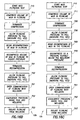
- the measurement phase 14 includes the steps of performing a second draw down 360, terminating the draw down 370, performing a second build up 380 and terminating the build up 390. These steps are performed as previously described according to the investigation phase 13 of Figure 6.
- the parameters of the measurement phase such as flow rate, time and/or volume, preferably have been predetermined according to the results of the investigation phase.
- the measurement phase 14 preferably begins at the termination of the investigation phase 350 and lasts for duration T MP specified by the measurement phase until termination at point 390.
- the total time to perform the investigation phase and the measurement phase falls within an allotted amount of time.
- the method 1b comprises a mud compressibility phase 11, an investigation phase 13 and a measurement phase 14.
- Estimations of mud compressibility may be used to refine the investigation phase procedure leading to better estimates of parameters from the investigation phase 13 and the measurement phase 14.
- Figure 11A depicts a pressure trace corresponding to the method of Figure 10, and Figure 11B shows a related graphical representation of the rate of change of the pretest chamber volume.
- the formation tester of Figure 4 may be used to perform the method of Figure 10.
- the isolation valves 121a and 124a may be used, in conjunction with equalizing valve 128a, to trap a volume of liquid in flowline 103a.
- the isolation valve 121a may be used to reduce tool storage volume effects so as to facilitate a rapid buildup.
- the equalizing valve 128a additionally allows for easy flushing of the flowline to expel unwanted fluids such as gas and to facilitate the refilling of the flowline sections 119a and 103a with wellbore fluid.
- the mud compressibility measurement may be performed, for example, by first drawing a volume of mud into the tool from the wellbore through the equalizing valve 128a by means of the pretest piston 118a, isolating a volume of mud in the flowline by closing the equalizing valve 128a and the isolation valves 121 a and 124a, compressing and/or expanding the volume of the trapped mud by adjusting the volume of the pretest chamber 114a by means of the pretest piston 118a and simultaneously recording the pressure and volume of the trapped fluid by means of the pressure gauge 120a.
- the volume of the pretest chamber may be measured very precisely, for example, by measuring the displacement of the pretest piston by means of a suitable linear potentiometer not shown in Figure 4 or by other well established techniques. Also not shown in Figure 4 is the means by which the speed of the pretest piston can be controlled precisely to give the desired control over the pretest piston rate q p .
- the techniques for achieving these precise rates are well known in the art, for example, by use of pistons attached to lead screws of the correct form, gearboxes and computer controlled motors such rates as are required by the present method can be readily achieved.
- Figures 11A and 12 depict the mud compressibility phase 11 in greater detail.
- the mud compressibility phase 11 is performed prior to setting the tool and therefore prior to conducting the investigation and measurement phases.
- the tool does not have to be set against the wellbore, nor does it have to be immobile in the wellbore in order to conduct the mud compressibility test thereby reducing the risk of sticking the tool due to an immobilized drill string. It would be preferable, however, to sample the wellbore fluid at a point close to the point of the test.
- the steps used to perform the compressibility phase 11 are shown in greater detail in Figure 12. These steps also correspond to points along the pressure trace of Figure 11 A.
- the steps of the mud compressibility test include starting the mud compressibility test 510, drawing mud from the wellbore into the tool 511, isolating the mud volume in the flow line 512, compressing the mud volume 520 and terminating the compression 530.
- the expansion of mud volume is started 540, the mud volume expands 550 for a period of time until terminated 560.
- Open communication of the flowline to wellbore is begun 561, and pressure is equalized in the flowline to wellbore pressure 570 until terminated 575.
- the pretest piston recycling may now begin 580. Mud is expelled from the flowline into the wellbore 581 and the pretest piston is recycled 582.
- the tool may then be set 610 and open communication of the flowline with the wellbore terminated 620.
- Mud compressibility relates to the compressibility of the flowline fluid, which typically is whole drilling mud.
- Knowledge of the mud compressibility may be used to better determine the slope of the line 32 (as previously described with respect to Figure 7), which in turn leads to an improved determination of the point of deviation 34 signaling flow from the formation.
- Knowledge of the value of mud compressibility therefore, results in a more efficient investigation phase 13 and provides an additional avenue to further refine the estimates derived from the investigation phase 13 and ultimately to improve those derived from the measurement phase 14.
- Mud compressibility C m may be determined by analyzing the pressure trace of Figure 11A and the pressure and volume data correspondingly generated.
- the utility of measuring the mud compressibility in obtaining a more precise deviation point 34a is now explained.
- the method begins by fitting the initial portion of the drawdown data of the investigation phase 13 to a line 32a of known slope to the data.
- the slope of line 32a is fixed by the previously determined mud compressibility, flowline volume, and the pretest piston drawdown rate.
- V (0) is the flowline volume at the beginning of the expansion
- C m is the mud compressibility
- q p is the piston decompression rate
- p + is the apparent pressure at the initiation of the expansion process. It is assumed that V(0) is very much larger than the increase in volume due to the expansion of the pretest chamber.
- intercept p + the only parameter that needs to be specified to completely define equation (17) is the intercept p + , ie., b.
- p + is unknown, however, when data points belonging to the linear trend of the flowline expansion are fitted to lines with slope a they should all produce similar intercepts. Thus, the value of intercept p + will emerge when the linear trend of the flowline expansion is identified.
- This line represents the true mud expansion drawdown pressure trend.
- One skilled in the art would appreciate that in fitting the data points to a line, it is unnecessary that all points fall precisely on the line. Instead, it is sufficient that the data points fit to a line within a precision limit, which is selected based on the tool characteristics and operation parameters. With this approach, one can avoid the irregular trend associated with early data points, i.e., those points around the start of pretest piston drawdown.
- the first point 34a after the points that define the straight line, that deviates significantly (or beyond a precision limit) from the line is the point where deviation from the drawdown pressure trend occurs. The deviation 34a typically occurs at a higher pressure than would be predicted by extrapolation of the line. This point indicates the breach of the mudcake.
- N ( k ) ⁇ k represents the number of data points selected from the k data points (t k , p k ) acquired.
- N ( k ) may equal k .
- Equations (18) and (19) represent, respectively, the least-squares line with fixed slope a and the line of least absolute deviation with fixed slope a through N(k) data points, and, equation (20) represents the variance of the data about the fixed slope line.
- the technique may involve the steps of: (i) determining a median, , from the given sequence of intercepts ⁇ b k ⁇ ; (ii) finding indices belonging to the set where n b is a number such as 2 or 3 and where a possible choice for ⁇ b is defined by the following equation: where the last expression results from the assumption that time measurements are exact.
- This point, represented by 34a on Figure 11 A, is taken to indicate a breach of the mudcake and the initiation of flow from the formation.
- a method according to the invention may be implemented as follows: (i) a line of fixed slope, a , is first fitted to the data accumulated up to the time t k .
- N(k) be the number of indices in the set; (v) determine the point of departure from the last of the series of fixed-slope lines having indices in the above set as the first point that fulfills p k - b k +at k > n S S p,k , where n S is a number such as 2 or 3; (vi) define (vii) find the subset of points of J k such that (viii) fit a line with slope a through the points with indices in N ; and (ix) define the breach of the mudcake as the first point (t k , p k ) where p k - b k + at k > n S S p,k . As in the previous option this point, represented again by 34a on Figure 11A, is taken to indicate a breach of the mudcake and the initiation of flow from the formation.
- the termination point 330a, the build up 370a and the termination of buildup 350a may be determined as discussed previously with respect to Figure 7.
- the measurement phase 14 may then be determined by the refined parameters generated in the investigation phase 13 of Figure 11 A.
- FIG. 13 an alternate embodiment of the method 1c incorporating a mud filtration phase 12 is depicted.
- the method comprises a mud compressibility phase 11a, a mud filtration phase12, an investigation phase 13 and a measurement phase 14.
- the corresponding pressure trace is depicted in Figure 14A, and a corresponding graphical depiction of the rate of change of pretest volume is shown in Figure 14B.
- the same tool described with respect to the method of Figure 10 may also be used in connection with the method of Figure 13.
- Figures 14A and 14B depict the mud filtration phase 12 in greater detail.
- the mud filtration phase 12 is performed after the tool is set and before the investigation phase 13 and the measurement phase 14 are performed.
- a modified mud compressibility phase 11a is performed prior to the mud filtration phase 12.
- the modified compressibility test 11a is depicted in greater detail in Figure 15.
- the modified compressibility test 11a includes the same steps 510-580 of the compressibility test 11 of Figure 12. After step 580, steps 511 and 512 of the mud compressibility test are repeated, namely mud is drawn from the wellbore into the tool 511a and the flowline is isolated from the wellbore 512a.
- the tool may now be set 610 and at the termination of the set cycle the flowline may be isolated 620 in preparation for the mud filtration, investigative and measurement phases.
- the mud filtration phase 12 is shown in greater detail in Figure 16A.
- the mud filtration phase is started at 710, the volume of mud in the flowline is compressed 711 until termination at point 720, and the flowline pressure falls 730. Following the initial compression, communication of the flowline within the wellbore is opened 751, pressures inside the tool and wellbore are equilibrated 752, and the flowline is isolated from the wellbore 753.
- a modified mud filtration phase 12b may be performed.
- a second compression is performed prior to opening communication of the flowline 751, including the steps of beginning recompression of mud in flowline 731, compressing volume of mud in flowline to higher pressure 740, terminating recompression 741.
- Flowline pressure is then permitted to fall 750.
- Steps 751-753 may then be performed as described with respect to Figure 16A.
- the pressure trace of Figure 14A shows the mud filtration phase 12b of Figure 16B.
- a decompression cycle may be performed following flowline pressure fall 730 of the first compression 711, including the steps of beginning the decompression of mud in the flowline 760, decompressing to a pressure suitably below the wellbore pressure 770, and terminating the decompression 780. Flowline pressure is then permitted to fall 750. Steps 751 - 753 may then be repeated as previously described with respect to Figure 16A.
- the pressure trace of Figure 14A shows the mud filtration phase 12c of Figure 16C.
- the mud filtration method 12 of Figure 16A may be performed with either the mud filtration phase 12b of Figure 16B or the mud filtration phase 12c of 16C.
- one or more of the techniques depicted in Figures 16A-C may be performed during the mud filtration phase.
- Mud filtration relates to the filtration of the base fluid of the mud through a mudcake deposited on the wellbore wall and the determination of the volumetric rate of the filtration under the existing wellbore conditions.
- V t is the total volume of the trapped mud (cm 3 )
- q f represents the mud filtration rate (cm 3 /sec)
- C m represents the mud compressibility (1/psi) (where C m is determined during the modified mud compressibility test 11a or input)
- p represents the rate of pressure decline (psi/sec) as measured during 730 and 750 in Figure 14.
- the volume V t in equation (22) is a representation of the volume of the flowline contained between valves 121a, 124a and 128a as shown in Figure 4.
- the slope, a of the fixed slope line used during the flowline decompression phase to detect the point of initiation of flow from the formation, ie the point of deviation, 34 Figure 7, under these circumstances is determined using the following equation: where V (0) is the flowline volume at the beginning of the expansion, C m is the mud compressibility, q p is the piston decompression rate, q f is the rate of filtration from the flow line through the mudcake into the formation, and p + is the apparent pressure at the initiation of the expansion process which, as previously explained, is determined during the process of determining the deviation point 34.
- embodiments of the invention may be implemented in an automatic manner.
- they are applicable to both downhole drilling tools and to a wireline formation tester conveyed downhole by any type of work string, such as drill string, wireline cable, jointed tubing, or coiled tubing.
- methods of the invention permit downhole drilling tools to perform time-constrained formation testing in a most time efficient manner such that potential problems associated with a stopped drilling tool can be minimized or avoided.
- the mud compressibility is preferably determined as described above (not shown).
- the pressure measured by the tool is the wellbore fluid, or mud hydrostatic, pressure 801.
- the pretest piston 118a is activated 810 to withdraw fluid at a precise and fixed rate to achieve a specified pressure drop 814 in a desired time t pi 815. It is preferred that the desired pressure drop ( ⁇ p) be of the same order but less than the expected overbalance at that depth, if the overbalance is approximately known.
- Overbalance is the difference in pressure between the mud hydrostatic pressure and the formation pressure.
- the desired pressure drop ( ⁇ p) may be some number (e.g., 300 psi) that is larger than the maximum expected value of the "flow initiation pressure" (e.g., 200 psi). Whether the actual formation pressure is within this range is immaterial to the embodiments of the invention. Therefore, the following description assumes that the formation pressure is not within the range.
- the stabilized pressure at point 820 is compared with the pressure at the start of the drawdown at point 810. At this point, a decision is made as to whether to repeat the cycle, shown as 819 in Figure 18. The criterion for the decision is whether the equalized pressure (e.g., at point 820) differs from the pressure at the start of the drawdown (e.g., at point 810) by an amount that is substantially consistent with the expected pressure drop ( ⁇ p ). If so, then this flowline expansion cycle is repeated.
- the pretest piston is re-activated and the drawdown cycle is repeated as described, namely, initiation of the pretest 820, drawdown 824 by exactly the same amount ( ⁇ p ) at substantially the same rate and duration 826 as for the previous cycle, termination of the drawdown 825, and stabilization 830.
- the pressures at 820 and 830 are compared to decide whether to repeat the cycle. As shown in Figure 17A, these pressures are significantly different and are substantially consistent with the expected pressure drop ( ⁇ p ) arising from expansion of the fluid in the flowline. Therefore, the cycle is repeated, 830-834-835-840.
- the "flowline expansion" cycle is repeated until the difference in consecutive stabilized pressures is substantially smaller than the imposed/prescribed pressure drop ( ⁇ p), shown for example in Figure 17A as 840 and 850.
- the "flowline expansion" cycle may be repeated one more time, shown as 850-854-855-860 in Figure 17A. If the stabilized pressures at 850 and 860 are in substantial agreement, for example within a small multiple of the gauge repeatability, the larger of the two values is taken as the first estimate of the formation pressure.
- the processes as shown in Figure 17A, 17B, and 18 are for illustration only. Embodiments of the invention are not limited by how many flowline expansion cycles are performed.
- the point at which the transition from flowline fluid expansion to flow from the formation takes place is identified as 800 in Figure 17A. If the pressures at 850 and 860 agree at the end of the allotted stabilization time, it may be advantageous to allow the pressure 860 to continue to build and use the procedures described in previous sections (see the description for Figure 8) to terminate the build up in order to obtain a better first estimate of the formation pressure.
- the process by which the decision is made to either continue the investigation phase or to perform the measurement phase, 864-868-869, to obtain a final estimate of the formation pressure 870 is described in previous sections. After the measurement phase is completed 870, the probe is disengaged from the wellbore wall and the pressure returns to the wellbore pressure 874 within a time period 895 and reaches stabilization at 881.
- the parameters thus obtained may be used to establish the measurement phase 14 pretest parameters that will produce more accurate formation parameters within the allotted time for the test.
- the procedures for using the parameters obtained in the investigation phase 13b to design the measurement phase 14 pretest parameters have been described in previous sections.
- the magnitude of the pressure drop ( ⁇ p ) during the flowline expansion phase is prescribed.
- the magnitude of the volume increase ( ⁇ V ) during the flowline expansion phase is prescribed.
- the procedures used in this embodiment are similar to those described for embodiments shown in Figures 17A, 17B, and 18.
- the mud compressibility is preferably determined (not shown).
- the pressure measured by the tool is the wellbore or mud hydrostatic pressure 201.
- a method for performing an investigation phase 13c comprises the steps of starting the drawdown 210, withdrawing fluid at a precise and fixed rate 214 until the volume of the pretest chamber 114a is increased by the prescribed amount ⁇ V .
- the incremental change in volume of the pretest chamber may be on the order of 0.2 to 1 cubic centimeter, for example.
- the amount of the prescribed volume increase ( ⁇ V ) is not limited to these exemplary volumes and should be chosen according to the total volume of the trapped fluid.
- the resulting expansion of the flowline fluid induces a pressure drop in the flowline.
- the pretest piston is re-activated 220
- the flowline is expanded by precisely the same volume ⁇ V 224
- the pressure is allowed to stabilize 230.
- the cycle is repeated, for example 230-234-235-240.
- the "flowline expansion” cycle is repeated until the difference in consecutive stabilized pressures, e.g., pressures at 230 and 240 as shown in Figure 19A, is substantially smaller than the expected pressure drop due to the expansion of fluid in the flowline.
- the "flowline expansion" cycle may be repeated one more time, shown as 240-244-245-250 in Figure 19A. If the stabilized pressures at 240 and 250 substantially agree, the larger of the two values is taken to represent the first estimate of the formation pressure.
- Figures 19A, 19B, and 20 are for illustration only. Embodiments of the invention are not limited by how many "flowline expansion" cycles are performed. Furthermore, after the difference in consecutive stabilized pressures is substantially smaller than the expected pressure drop, it is optional to repeat the cycle one or more times.
- the point at which the transition from flowline fluid expansion to flow from the formation takes place is identified as 300 in Figure 19A. If the pressures at 240 and 250 agree to within a selected limit (e.g., a small multiple of the gauge repeatability) at the end of the allotted stabilization time, it may be advantageous to allow the pressure at 250 to continue to build and use the procedure disclosed in the previous section (see Figure 8) to terminate the build up in order to obtain a better first estimate of the formation pressure.
- the process by which the decision to continue the investigation phase or whether to execute the measurement phase, 250-258-259-260, to obtain a final estimate of the formation pressure 260 is as described in previous sections. After the measurement phase is completed 260, the probe is disengaged from the wellbore wall and the pressure returns to the wellbore pressure 264 within a time period 295 and reaches stabilization at 271.
- the parameters thus obtained may be used to establish the measurement phase 14 pretest parameters that will produce more accurate formation parameters within the allotted time for the test.
- the procedures for using the parameters obtained in the investigation phase 13c to design the measurement phase 14 pretest parameters have been described in previous sections.
- mud compressibility is dependent on its composition and on the temperature and the pressure of the fluid. As a result, the mud compressibility often changes with depth. Therefore, it is desirable to measure the mud compressibility in situ at a location near where the testing is to be performed. If the tool configuration does not allow the mud compressibility to be determined as described above, the in-situ mud compressibility may be estimated by alternate methods as described in the following.
- the formation tester may be set in casing, for example near the casing shoe, to establish a fluid seal with the casing.
- the true vertical depth (hence, the temperature and pressure) at which the compressibility measurement is performed may be significantly different from the depth where the formation pressure is to be measured. Because the compressibility of drilling fluids is affected by temperature and pressure, it would be necessary to apply a correction to the compressibility thus measured in order to estimate the compressibility of the drilling mud at the depth where the testing is to be performed.
- the wellbore pressure and temperature information are acquired before the measurement begins, e.g., at point 801 as shown in Figure 17A, using conventional pressure and temperature sensors.
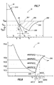
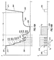
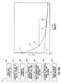
- charts as shown in Figure 21 may be constructed for the purpose of conducting temperature and pressure corrections.
- analytical methods known in the art may be used to compute correction factors which when applied to the original compressibility measurement will provide the in-situ flowline fluid compressibility at the depth at which the formation pressure is to be measured. See e.g., E. Kartstad and B.S. Aadnoy, "Density Behavior of Drilling Fluids During High Pressure High Temperature Drilling Operations," IADC/SPE paper 47806, 1998.
- the compressibility of a surface-derived (e.g., mud-pit) sample over the range of expected downhole temperature and pressure conditions are measured.
- An estimate of the in-situ mud compressibility under the downhole conditions may then be estimated from known relationships between the mud density and mud pressure and mud temperature according to methods known in the art. See, e.g. , Figure 21 and E. Kartstad and B.S. Aadnoy, "Density Behavior of Drilling Fluids During High Pressure High Temperature Drilling Operations," IADC/SPE paper 47806, 1998.
- Figure 21 depicts a typical relationship between fluid compressibility ( C m ) and fluid pressure (p) for oil based and water based muds.
- Solid line 10 depicts the variation in mud compressibility with wellbore pressure for a typical oil based mud.
- Dashed line 11 depicts the corresponding variation in mud compressibility for a typical water based mud.
- the compressibility of the oil based mud at the surface is represented by reference number 7.
- the compressibility of the oil based mud at the casing shoe is represented by reference number 8.
- the compressibility of the oil based mud at a given measurement depth below the casing shoe is represented by reference number 9.
- the compressibility correction ⁇ C represents the difference between the compressibility of the oil based mud at the casing shoe 8 and that at the measurement depth 9.
- the compressibility measurement made at the casing shoe 8 may be adjusted by the compressibility correction ⁇ C to determine the compressibility at the measurement depth 9.
- the change in compressibility and corresponding compressibility correction for water based muds may be less significant than the correction depicted by the solid line 10 for oil based muds.
- mud compressibility under the downhole conditions may be used in embodiments of the invention to improve the accuracy of the estimates of formation properties from the investigation phase and/or measurement phase as shown, for example, in Figure 11A.
Landscapes
- Engineering & Computer Science (AREA)
- Mining & Mineral Resources (AREA)
- Geology (AREA)
- Life Sciences & Earth Sciences (AREA)
- Geochemistry & Mineralogy (AREA)
- Environmental & Geological Engineering (AREA)
- Fluid Mechanics (AREA)
- Physics & Mathematics (AREA)
- General Life Sciences & Earth Sciences (AREA)
- Analytical Chemistry (AREA)
- Chemical & Material Sciences (AREA)
- Measuring Fluid Pressure (AREA)
- Testing Of Devices, Machine Parts, Or Other Structures Thereof (AREA)
- Investigating Or Analyzing Non-Biological Materials By The Use Of Chemical Means (AREA)
- Investigating Or Analysing Materials By The Use Of Chemical Reactions (AREA)
- Investigation Of Foundation Soil And Reinforcement Of Foundation Soil By Compacting Or Drainage (AREA)
- Geophysics And Detection Of Objects (AREA)
- Treatments Of Macromolecular Shaped Articles (AREA)
- Investigating Strength Of Materials By Application Of Mechanical Stress (AREA)
- Treatment Of Sludge (AREA)
Priority Applications (2)
| Application Number | Priority Date | Filing Date | Title |
|---|---|---|---|
| EP05006754A EP1553260A3 (fr) | 2002-09-09 | 2003-09-02 | Procédé de détermination de la compressibilité de la boue de forage |
| EP07023533.8A EP1898046B1 (fr) | 2002-09-09 | 2003-09-02 | Procédé de mesure des propriétés d'une formation |
Applications Claiming Priority (4)
| Application Number | Priority Date | Filing Date | Title |
|---|---|---|---|
| US10/237,394 US6832515B2 (en) | 2002-09-09 | 2002-09-09 | Method for measuring formation properties with a time-limited formation test |
| US237394 | 2002-09-09 | ||
| US10/434,923 US7263880B2 (en) | 2002-09-09 | 2003-05-09 | Method for measuring formation properties with a time-limited formation test |
| US434923 | 2003-05-09 |
Related Child Applications (1)
| Application Number | Title | Priority Date | Filing Date |
|---|---|---|---|
| EP05006754A Division EP1553260A3 (fr) | 2002-09-09 | 2003-09-02 | Procédé de détermination de la compressibilité de la boue de forage |
Publications (3)
| Publication Number | Publication Date |
|---|---|
| EP1396607A2 true EP1396607A2 (fr) | 2004-03-10 |
| EP1396607A3 EP1396607A3 (fr) | 2004-06-16 |
| EP1396607B1 EP1396607B1 (fr) | 2006-06-07 |
Family
ID=31980981
Family Applications (1)
| Application Number | Title | Priority Date | Filing Date |
|---|---|---|---|
| EP03255458A Expired - Lifetime EP1396607B1 (fr) | 2002-09-09 | 2003-09-02 | Procédé de mesure de caractéristiques de formation à l'aide d'un test de formation à durée limitée |
Country Status (9)
| Country | Link |
|---|---|
| EP (1) | EP1396607B1 (fr) |
| CN (1) | CN100379939C (fr) |
| AT (1) | ATE329136T1 (fr) |
| AU (1) | AU2003244534B2 (fr) |
| CA (1) | CA2440494C (fr) |
| DE (1) | DE60305816T2 (fr) |
| MX (1) | MXPA03007913A (fr) |
| NO (1) | NO332820B1 (fr) |
| RU (1) | RU2316650C2 (fr) |
Cited By (6)
| Publication number | Priority date | Publication date | Assignee | Title |
|---|---|---|---|---|
| GB2447322A (en) * | 2007-03-05 | 2008-09-10 | Schlumberger Holdings | Generating well logs |
| GB2493053A (en) * | 2011-07-22 | 2013-01-23 | Precision Energy Services Inc | Autonomous Formation Pressure Test Process for Formation Evaluation Tool |
| WO2015026901A1 (fr) * | 2013-08-22 | 2015-02-26 | Baker Hughes Incorporated | Analyse de débit modifiée |
| US9890630B2 (en) | 2010-12-03 | 2018-02-13 | Total S.A. | Method for measuring pressure in an underground formation |
| CN110617057A (zh) * | 2019-09-17 | 2019-12-27 | 中海艾普油气测试(天津)有限公司 | 一种全管式井下测试管柱及其测试方法 |
| WO2020185295A1 (fr) * | 2019-03-08 | 2020-09-17 | Halliburton Energy Services, Inc. | Réalisation d'un essai de pression de fond de trou |
Families Citing this family (4)
| Publication number | Priority date | Publication date | Assignee | Title |
|---|---|---|---|---|
| US6672386B2 (en) * | 2002-06-06 | 2004-01-06 | Baker Hughes Incorporated | Method for in-situ analysis of formation parameters |
| US9581019B2 (en) | 2011-03-23 | 2017-02-28 | Schlumberger Technology Corporation | Measurement pretest drawdown methods and apparatus |
| CN113605879B (zh) * | 2021-08-02 | 2023-03-21 | 中国石油大学(北京) | 煤储层原始地层压力的计算方法及装置 |
| CN119247474B (zh) * | 2023-06-28 | 2025-10-03 | 中国石油天然气集团有限公司 | 气测曲线形态函数判别地层流体性质的方法 |
Citations (7)
| Publication number | Priority date | Publication date | Assignee | Title |
|---|---|---|---|---|
| US3934468A (en) | 1975-01-22 | 1976-01-27 | Schlumberger Technology Corporation | Formation-testing apparatus |
| US4860581A (en) | 1988-09-23 | 1989-08-29 | Schlumberger Technology Corporation | Down hole tool for determination of formation properties |
| US4936139A (en) | 1988-09-23 | 1990-06-26 | Schlumberger Technology Corporation | Down hole method for determination of formation properties |
| US5095745A (en) | 1990-06-15 | 1992-03-17 | Louisiana State University | Method and apparatus for testing subsurface formations |
| US5233866A (en) | 1991-04-22 | 1993-08-10 | Gulf Research Institute | Apparatus and method for accurately measuring formation pressures |
| US5969241A (en) | 1996-04-10 | 1999-10-19 | Schlumberger Technology Corporation | Method and apparatus for measuring formation pressure |
| US6230557B1 (en) | 1998-08-04 | 2001-05-15 | Schlumberger Technology Corporation | Formation pressure measurement while drilling utilizing a non-rotating sleeve |
Family Cites Families (12)
| Publication number | Priority date | Publication date | Assignee | Title |
|---|---|---|---|---|
| US3448611A (en) * | 1966-09-29 | 1969-06-10 | Schlumberger Technology Corp | Method and apparatus for formation testing |
| US3811321A (en) * | 1972-12-08 | 1974-05-21 | Schlumberger Technology Corp | Methods and apparatus for testing earth formations |
| SU1038473A2 (ru) * | 1979-06-25 | 1983-08-30 | Всесоюзный научно-исследовательский институт нефтепромысловой геофизики | Устройство на кабеле дл исследовани пластов в необсаженных скважинах |
| US4513612A (en) * | 1983-06-27 | 1985-04-30 | Halliburton Company | Multiple flow rate formation testing device and method |
| US4745802A (en) * | 1986-09-18 | 1988-05-24 | Halliburton Company | Formation testing tool and method of obtaining post-test drawdown and pressure readings |
| US4742459A (en) * | 1986-09-29 | 1988-05-03 | Schlumber Technology Corp. | Method and apparatus for determining hydraulic properties of formations surrounding a borehole |
| US5184508A (en) * | 1990-06-15 | 1993-02-09 | Louisiana State University And Agricultural And Mechanical College | Method for determining formation pressure |
| US5635631A (en) * | 1992-06-19 | 1997-06-03 | Western Atlas International, Inc. | Determining fluid properties from pressure, volume and temperature measurements made by electric wireline formation testing tools |
| US5329811A (en) * | 1993-02-04 | 1994-07-19 | Halliburton Company | Downhole fluid property measurement tool |
| US5703286A (en) * | 1995-10-20 | 1997-12-30 | Halliburton Energy Services, Inc. | Method of formation testing |
| US6301959B1 (en) * | 1999-01-26 | 2001-10-16 | Halliburton Energy Services, Inc. | Focused formation fluid sampling probe |
| US6427530B1 (en) * | 2000-10-27 | 2002-08-06 | Baker Hughes Incorporated | Apparatus and method for formation testing while drilling using combined absolute and differential pressure measurement |
-
2003
- 2003-09-02 AT AT03255458T patent/ATE329136T1/de not_active IP Right Cessation
- 2003-09-02 EP EP03255458A patent/EP1396607B1/fr not_active Expired - Lifetime
- 2003-09-02 DE DE60305816T patent/DE60305816T2/de not_active Expired - Lifetime
- 2003-09-03 AU AU2003244534A patent/AU2003244534B2/en not_active Ceased
- 2003-09-03 MX MXPA03007913A patent/MXPA03007913A/es active IP Right Grant
- 2003-09-08 NO NO20033971A patent/NO332820B1/no not_active IP Right Cessation
- 2003-09-08 RU RU2003127112/03A patent/RU2316650C2/ru not_active IP Right Cessation
- 2003-09-08 CA CA002440494A patent/CA2440494C/fr not_active Expired - Fee Related
- 2003-09-09 CN CNB031255930A patent/CN100379939C/zh not_active Expired - Fee Related
Patent Citations (7)
| Publication number | Priority date | Publication date | Assignee | Title |
|---|---|---|---|---|
| US3934468A (en) | 1975-01-22 | 1976-01-27 | Schlumberger Technology Corporation | Formation-testing apparatus |
| US4860581A (en) | 1988-09-23 | 1989-08-29 | Schlumberger Technology Corporation | Down hole tool for determination of formation properties |
| US4936139A (en) | 1988-09-23 | 1990-06-26 | Schlumberger Technology Corporation | Down hole method for determination of formation properties |
| US5095745A (en) | 1990-06-15 | 1992-03-17 | Louisiana State University | Method and apparatus for testing subsurface formations |
| US5233866A (en) | 1991-04-22 | 1993-08-10 | Gulf Research Institute | Apparatus and method for accurately measuring formation pressures |
| US5969241A (en) | 1996-04-10 | 1999-10-19 | Schlumberger Technology Corporation | Method and apparatus for measuring formation pressure |
| US6230557B1 (en) | 1998-08-04 | 2001-05-15 | Schlumberger Technology Corporation | Formation pressure measurement while drilling utilizing a non-rotating sleeve |
Non-Patent Citations (3)
| Title |
|---|
| GOODE ET AL: "Multiple Probe Formation Testing and Vertical Reservoir Continuity", SPE 22738 - ANNUAL TECHN.CONF. AND EXHIBITION, 6 October 1991 (1991-10-06), DALLAS, TEXAS |
| KARTSTAD E. AND AADNOY B.S.: "Density Behavior of Drilling Fluids During High Temperature Drilling Operations.", IADC/SPE PAPER 47806, 1998 |
| KUCHUK F.J.: "Multiprobe Wireline Formation Tester Pressure Behavior in Crossflow-Layered Reservoirs.", IN SITU, vol. 20, no. 1,1, 1996 |
Cited By (15)
| Publication number | Priority date | Publication date | Assignee | Title |
|---|---|---|---|---|
| GB2447322A (en) * | 2007-03-05 | 2008-09-10 | Schlumberger Holdings | Generating well logs |
| RU2459950C2 (ru) * | 2007-03-05 | 2012-08-27 | Шлюмбергер Текнолоджи Б.В. | Системы и способы для сжатия данных скважины |
| US9890630B2 (en) | 2010-12-03 | 2018-02-13 | Total S.A. | Method for measuring pressure in an underground formation |
| US9771797B2 (en) | 2011-07-22 | 2017-09-26 | Precision Energy Services, Inc. | Autonomous formation pressure test process for formation evaluation tool |
| US8839668B2 (en) | 2011-07-22 | 2014-09-23 | Precision Energy Services, Inc. | Autonomous formation pressure test process for formation evaluation tool |
| GB2493053B (en) * | 2011-07-22 | 2014-03-19 | Precision Energy Services Inc | Autonomous formation pressure test process for formation evaluation tool |
| GB2493053A (en) * | 2011-07-22 | 2013-01-23 | Precision Energy Services Inc | Autonomous Formation Pressure Test Process for Formation Evaluation Tool |
| WO2015026901A1 (fr) * | 2013-08-22 | 2015-02-26 | Baker Hughes Incorporated | Analyse de débit modifiée |
| WO2020185295A1 (fr) * | 2019-03-08 | 2020-09-17 | Halliburton Energy Services, Inc. | Réalisation d'un essai de pression de fond de trou |
| US11008853B2 (en) | 2019-03-08 | 2021-05-18 | Halliburton Energy Services, Inc. | Performing a downhole pressure test |
| US11661839B2 (en) | 2019-03-08 | 2023-05-30 | Halliburton Energy Services, Inc. | Method and system for performing formation fluid test, involves performing second test with second set of tool parameters and comparing |
| US11808137B2 (en) | 2019-03-08 | 2023-11-07 | Halliburton Energy Services, Inc. | Method and system for performing pressure test by determining formation parameter from pressure test where stabilizer is activated into surface of wellbore which is placed on formation testing tool |
| US12091963B2 (en) | 2019-03-08 | 2024-09-17 | Halliburton Energy Services, Inc. | Performing a downhole pressure test |
| CN110617057A (zh) * | 2019-09-17 | 2019-12-27 | 中海艾普油气测试(天津)有限公司 | 一种全管式井下测试管柱及其测试方法 |
| CN110617057B (zh) * | 2019-09-17 | 2023-05-02 | 中海艾普油气测试(天津)有限公司 | 一种全管式井下测试管柱及其测试方法 |
Also Published As
| Publication number | Publication date |
|---|---|
| RU2003127112A (ru) | 2005-03-10 |
| NO20033971D0 (no) | 2003-09-08 |
| ATE329136T1 (de) | 2006-06-15 |
| CA2440494A1 (fr) | 2004-03-09 |
| CN100379939C (zh) | 2008-04-09 |
| AU2003244534B2 (en) | 2006-05-18 |
| AU2003244534A1 (en) | 2004-03-25 |
| NO20033971L (no) | 2004-03-10 |
| MXPA03007913A (es) | 2004-03-12 |
| EP1396607A3 (fr) | 2004-06-16 |
| DE60305816D1 (de) | 2006-07-20 |
| DE60305816T2 (de) | 2007-01-04 |
| CN1495336A (zh) | 2004-05-12 |
| NO332820B1 (no) | 2013-01-21 |
| RU2316650C2 (ru) | 2008-02-10 |
| EP1396607B1 (fr) | 2006-06-07 |
| CA2440494C (fr) | 2007-06-05 |
Similar Documents
| Publication | Publication Date | Title |
|---|---|---|
| EP1898046B1 (fr) | Procédé de mesure des propriétés d'une formation | |
| US8136395B2 (en) | Systems and methods for well data analysis | |
| CN101260804B (zh) | 用于井数据压缩的系统和方法 | |
| WO2005084332A2 (fr) | Procedes de mesure de la pression de suralimentation d'une formation | |
| EP1396607B1 (fr) | Procédé de mesure de caractéristiques de formation à l'aide d'un test de formation à durée limitée | |
| CA2535054C (fr) | Procede d'utilisation d'un appareil d'essai pour determiner les proprietes des formations dans un puits de forage penetrant une formation souterraine | |
| GB2456429A (en) | Generating well logs |
Legal Events
| Date | Code | Title | Description |
|---|---|---|---|
| PUAI | Public reference made under article 153(3) epc to a published international application that has entered the european phase |
Free format text: ORIGINAL CODE: 0009012 |
|
| AK | Designated contracting states |
Kind code of ref document: A2 Designated state(s): AT BE BG CH CY CZ DE DK EE ES FI FR GB GR HU IE IT LI LU MC NL PT RO SE SI SK TR |
|
| AX | Request for extension of the european patent |
Extension state: AL LT LV MK |
|
| PUAL | Search report despatched |
Free format text: ORIGINAL CODE: 0009013 |
|
| AK | Designated contracting states |
Kind code of ref document: A3 Designated state(s): AT BE BG CH CY CZ DE DK EE ES FI FR GB GR HU IE IT LI LU MC NL PT RO SE SI SK TR |
|
| AX | Request for extension of the european patent |
Extension state: AL LT LV MK |
|
| 17P | Request for examination filed |
Effective date: 20040818 |
|
| 17Q | First examination report despatched |
Effective date: 20041119 |
|
| AKX | Designation fees paid |
Designated state(s): AT BE BG CH CY CZ DE DK EE ES FI FR GB GR HU IE IT LI LU MC NL PT RO SE SI SK TR |
|
| GRAP | Despatch of communication of intention to grant a patent |
Free format text: ORIGINAL CODE: EPIDOSNIGR1 |
|
| GRAS | Grant fee paid |
Free format text: ORIGINAL CODE: EPIDOSNIGR3 |
|
| GRAA | (expected) grant |
Free format text: ORIGINAL CODE: 0009210 |
|
| AK | Designated contracting states |
Kind code of ref document: B1 Designated state(s): AT BE BG CH CY CZ DE DK EE ES FI FR GB GR HU IE IT LI LU MC NL PT RO SE SI SK TR |
|
| PG25 | Lapsed in a contracting state [announced via postgrant information from national office to epo] |
Ref country code: CH Free format text: LAPSE BECAUSE OF FAILURE TO SUBMIT A TRANSLATION OF THE DESCRIPTION OR TO PAY THE FEE WITHIN THE PRESCRIBED TIME-LIMIT Effective date: 20060607 Ref country code: RO Free format text: LAPSE BECAUSE OF FAILURE TO SUBMIT A TRANSLATION OF THE DESCRIPTION OR TO PAY THE FEE WITHIN THE PRESCRIBED TIME-LIMIT Effective date: 20060607 Ref country code: FI Free format text: LAPSE BECAUSE OF FAILURE TO SUBMIT A TRANSLATION OF THE DESCRIPTION OR TO PAY THE FEE WITHIN THE PRESCRIBED TIME-LIMIT Effective date: 20060607 Ref country code: SI Free format text: LAPSE BECAUSE OF FAILURE TO SUBMIT A TRANSLATION OF THE DESCRIPTION OR TO PAY THE FEE WITHIN THE PRESCRIBED TIME-LIMIT Effective date: 20060607 Ref country code: AT Free format text: LAPSE BECAUSE OF FAILURE TO SUBMIT A TRANSLATION OF THE DESCRIPTION OR TO PAY THE FEE WITHIN THE PRESCRIBED TIME-LIMIT Effective date: 20060607 Ref country code: NL Free format text: LAPSE BECAUSE OF FAILURE TO SUBMIT A TRANSLATION OF THE DESCRIPTION OR TO PAY THE FEE WITHIN THE PRESCRIBED TIME-LIMIT Effective date: 20060607 Ref country code: LI Free format text: LAPSE BECAUSE OF FAILURE TO SUBMIT A TRANSLATION OF THE DESCRIPTION OR TO PAY THE FEE WITHIN THE PRESCRIBED TIME-LIMIT Effective date: 20060607 Ref country code: CZ Free format text: LAPSE BECAUSE OF FAILURE TO SUBMIT A TRANSLATION OF THE DESCRIPTION OR TO PAY THE FEE WITHIN THE PRESCRIBED TIME-LIMIT Effective date: 20060607 Ref country code: BE Free format text: LAPSE BECAUSE OF FAILURE TO SUBMIT A TRANSLATION OF THE DESCRIPTION OR TO PAY THE FEE WITHIN THE PRESCRIBED TIME-LIMIT Effective date: 20060607 Ref country code: SK Free format text: LAPSE BECAUSE OF FAILURE TO SUBMIT A TRANSLATION OF THE DESCRIPTION OR TO PAY THE FEE WITHIN THE PRESCRIBED TIME-LIMIT Effective date: 20060607 Ref country code: IT Free format text: LAPSE BECAUSE OF FAILURE TO SUBMIT A TRANSLATION OF THE DESCRIPTION OR TO PAY THE FEE WITHIN THE PRESCRIBED TIME-LIMIT;WARNING: LAPSES OF ITALIAN PATENTS WITH EFFECTIVE DATE BEFORE 2007 MAY HAVE OCCURRED AT ANY TIME BEFORE 2007. THE CORRECT EFFECTIVE DATE MAY BE DIFFERENT FROM THE ONE RECORDED. Effective date: 20060607 |
|
| REG | Reference to a national code |
Ref country code: GB Ref legal event code: FG4D |
|
| REG | Reference to a national code |
Ref country code: CH Ref legal event code: EP |
|
| REG | Reference to a national code |
Ref country code: IE Ref legal event code: FG4D |
|
| REF | Corresponds to: |
Ref document number: 60305816 Country of ref document: DE Date of ref document: 20060720 Kind code of ref document: P |
|
| PG25 | Lapsed in a contracting state [announced via postgrant information from national office to epo] |
Ref country code: IE Free format text: LAPSE BECAUSE OF NON-PAYMENT OF DUE FEES Effective date: 20060904 |
|
| PG25 | Lapsed in a contracting state [announced via postgrant information from national office to epo] |
Ref country code: SE Free format text: LAPSE BECAUSE OF FAILURE TO SUBMIT A TRANSLATION OF THE DESCRIPTION OR TO PAY THE FEE WITHIN THE PRESCRIBED TIME-LIMIT Effective date: 20060907 Ref country code: DK Free format text: LAPSE BECAUSE OF FAILURE TO SUBMIT A TRANSLATION OF THE DESCRIPTION OR TO PAY THE FEE WITHIN THE PRESCRIBED TIME-LIMIT Effective date: 20060907 |
|
| PG25 | Lapsed in a contracting state [announced via postgrant information from national office to epo] |
Ref country code: ES Free format text: LAPSE BECAUSE OF FAILURE TO SUBMIT A TRANSLATION OF THE DESCRIPTION OR TO PAY THE FEE WITHIN THE PRESCRIBED TIME-LIMIT Effective date: 20060918 |
|
| PG25 | Lapsed in a contracting state [announced via postgrant information from national office to epo] |
Ref country code: MC Free format text: LAPSE BECAUSE OF NON-PAYMENT OF DUE FEES Effective date: 20060930 |
|
| PG25 | Lapsed in a contracting state [announced via postgrant information from national office to epo] |
Ref country code: PT Free format text: LAPSE BECAUSE OF FAILURE TO SUBMIT A TRANSLATION OF THE DESCRIPTION OR TO PAY THE FEE WITHIN THE PRESCRIBED TIME-LIMIT Effective date: 20061107 |
|
| NLV1 | Nl: lapsed or annulled due to failure to fulfill the requirements of art. 29p and 29m of the patents act | ||
| REG | Reference to a national code |
Ref country code: CH Ref legal event code: PL |
|
| ET | Fr: translation filed | ||
| PLBE | No opposition filed within time limit |
Free format text: ORIGINAL CODE: 0009261 |
|
| STAA | Information on the status of an ep patent application or granted ep patent |
Free format text: STATUS: NO OPPOSITION FILED WITHIN TIME LIMIT |
|
| 26N | No opposition filed |
Effective date: 20070308 |
|
| PG25 | Lapsed in a contracting state [announced via postgrant information from national office to epo] |
Ref country code: GR Free format text: LAPSE BECAUSE OF FAILURE TO SUBMIT A TRANSLATION OF THE DESCRIPTION OR TO PAY THE FEE WITHIN THE PRESCRIBED TIME-LIMIT Effective date: 20060908 |
|
| PG25 | Lapsed in a contracting state [announced via postgrant information from national office to epo] |
Ref country code: EE Free format text: LAPSE BECAUSE OF FAILURE TO SUBMIT A TRANSLATION OF THE DESCRIPTION OR TO PAY THE FEE WITHIN THE PRESCRIBED TIME-LIMIT Effective date: 20060607 Ref country code: BG Free format text: LAPSE BECAUSE OF FAILURE TO SUBMIT A TRANSLATION OF THE DESCRIPTION OR TO PAY THE FEE WITHIN THE PRESCRIBED TIME-LIMIT Effective date: 20060907 |
|
| PG25 | Lapsed in a contracting state [announced via postgrant information from national office to epo] |
Ref country code: TR Free format text: LAPSE BECAUSE OF FAILURE TO SUBMIT A TRANSLATION OF THE DESCRIPTION OR TO PAY THE FEE WITHIN THE PRESCRIBED TIME-LIMIT Effective date: 20060607 Ref country code: HU Free format text: LAPSE BECAUSE OF FAILURE TO SUBMIT A TRANSLATION OF THE DESCRIPTION OR TO PAY THE FEE WITHIN THE PRESCRIBED TIME-LIMIT Effective date: 20061208 Ref country code: LU Free format text: LAPSE BECAUSE OF NON-PAYMENT OF DUE FEES Effective date: 20060902 |
|
| PG25 | Lapsed in a contracting state [announced via postgrant information from national office to epo] |
Ref country code: CY Free format text: LAPSE BECAUSE OF FAILURE TO SUBMIT A TRANSLATION OF THE DESCRIPTION OR TO PAY THE FEE WITHIN THE PRESCRIBED TIME-LIMIT Effective date: 20060607 |
|
| REG | Reference to a national code |
Ref country code: FR Ref legal event code: PLFP Year of fee payment: 14 |
|
| REG | Reference to a national code |
Ref country code: FR Ref legal event code: PLFP Year of fee payment: 15 |
|
| PGFP | Annual fee paid to national office [announced via postgrant information from national office to epo] |
Ref country code: FR Payment date: 20170928 Year of fee payment: 15 |
|
| PGFP | Annual fee paid to national office [announced via postgrant information from national office to epo] |
Ref country code: DE Payment date: 20171130 Year of fee payment: 15 |
|
| REG | Reference to a national code |
Ref country code: DE Ref legal event code: R119 Ref document number: 60305816 Country of ref document: DE |
|
| PG25 | Lapsed in a contracting state [announced via postgrant information from national office to epo] |
Ref country code: DE Free format text: LAPSE BECAUSE OF NON-PAYMENT OF DUE FEES Effective date: 20190402 |
|
| PG25 | Lapsed in a contracting state [announced via postgrant information from national office to epo] |
Ref country code: FR Free format text: LAPSE BECAUSE OF NON-PAYMENT OF DUE FEES Effective date: 20180930 |
|
| PGFP | Annual fee paid to national office [announced via postgrant information from national office to epo] |
Ref country code: GB Payment date: 20220714 Year of fee payment: 20 |
|
| REG | Reference to a national code |
Ref country code: GB Ref legal event code: PE20 Expiry date: 20230901 |
|
| PG25 | Lapsed in a contracting state [announced via postgrant information from national office to epo] |
Ref country code: GB Free format text: LAPSE BECAUSE OF EXPIRATION OF PROTECTION Effective date: 20230901 |
|
| P01 | Opt-out of the competence of the unified patent court (upc) registered |
Effective date: 20231208 |