EP1396609A2 - Turbine à gaz avec passage de refroidissement délimité par une entretoise et un disque de rotor de turbine - Google Patents
Turbine à gaz avec passage de refroidissement délimité par une entretoise et un disque de rotor de turbine Download PDFInfo
- Publication number
- EP1396609A2 EP1396609A2 EP03019480A EP03019480A EP1396609A2 EP 1396609 A2 EP1396609 A2 EP 1396609A2 EP 03019480 A EP03019480 A EP 03019480A EP 03019480 A EP03019480 A EP 03019480A EP 1396609 A2 EP1396609 A2 EP 1396609A2
- Authority
- EP
- European Patent Office
- Prior art keywords
- turbine
- disk
- compressor
- gas turbine
- cooling
- Prior art date
- Legal status (The legal status is an assumption and is not a legal conclusion. Google has not performed a legal analysis and makes no representation as to the accuracy of the status listed.)
- Withdrawn
Links
- 125000006850 spacer group Chemical group 0.000 title claims abstract description 62
- 238000001816 cooling Methods 0.000 title claims description 55
- 238000007789 sealing Methods 0.000 claims description 12
- 230000006835 compression Effects 0.000 claims description 4
- 238000007906 compression Methods 0.000 claims description 4
- 238000002513 implantation Methods 0.000 claims description 2
- 239000007789 gas Substances 0.000 description 39
- 239000000567 combustion gas Substances 0.000 description 11
- 210000003027 ear inner Anatomy 0.000 description 3
- 239000000463 material Substances 0.000 description 3
- 238000005452 bending Methods 0.000 description 2
- 238000010586 diagram Methods 0.000 description 2
- 238000011156 evaluation Methods 0.000 description 2
- 238000003754 machining Methods 0.000 description 2
- 230000005540 biological transmission Effects 0.000 description 1
- 239000002826 coolant Substances 0.000 description 1
- 239000012530 fluid Substances 0.000 description 1
- 239000000446 fuel Substances 0.000 description 1
- 230000002401 inhibitory effect Effects 0.000 description 1
- 238000012423 maintenance Methods 0.000 description 1
- 238000000034 method Methods 0.000 description 1
- 230000002093 peripheral effect Effects 0.000 description 1
- 238000004513 sizing Methods 0.000 description 1
Images


Classifications
-
- F—MECHANICAL ENGINEERING; LIGHTING; HEATING; WEAPONS; BLASTING
- F01—MACHINES OR ENGINES IN GENERAL; ENGINE PLANTS IN GENERAL; STEAM ENGINES
- F01D—NON-POSITIVE DISPLACEMENT MACHINES OR ENGINES, e.g. STEAM TURBINES
- F01D5/00—Blades; Blade-carrying members; Heating, heat-insulating, cooling or antivibration means on the blades or the members
- F01D5/02—Blade-carrying members, e.g. rotors
- F01D5/06—Rotors for more than one axial stage, e.g. of drum or multiple disc type; Details thereof, e.g. shafts, shaft connections
- F01D5/066—Connecting means for joining rotor-discs or rotor-elements together, e.g. by a central bolt, by clamps
-
- F—MECHANICAL ENGINEERING; LIGHTING; HEATING; WEAPONS; BLASTING
- F01—MACHINES OR ENGINES IN GENERAL; ENGINE PLANTS IN GENERAL; STEAM ENGINES
- F01D—NON-POSITIVE DISPLACEMENT MACHINES OR ENGINES, e.g. STEAM TURBINES
- F01D11/00—Preventing or minimising internal leakage of working-fluid, e.g. between stages
- F01D11/005—Sealing means between non relatively rotating elements
-
- F—MECHANICAL ENGINEERING; LIGHTING; HEATING; WEAPONS; BLASTING
- F01—MACHINES OR ENGINES IN GENERAL; ENGINE PLANTS IN GENERAL; STEAM ENGINES
- F01D—NON-POSITIVE DISPLACEMENT MACHINES OR ENGINES, e.g. STEAM TURBINES
- F01D5/00—Blades; Blade-carrying members; Heating, heat-insulating, cooling or antivibration means on the blades or the members
- F01D5/02—Blade-carrying members, e.g. rotors
- F01D5/025—Fixing blade carrying members on shafts
Definitions
- the present invention relates to a gas turbine and a seal member for use therein, and in particular to a gas turbine and a spacer member for use therein, in which a compressor constructing the gas turbine uses a part of compressed air for cooling a turbine rotor blade thereof.
- a cooling air that is adjusted in flow-rate thereof is supplied into the cavity, for the purpose of guiding a desired amount of cooling air for the rotor blades.
- the similar gas turbine is also described in Japanese PCT Publication No. 2001-527178 (2001), for example.
- a fin is provided on a cover, thereby preventing the combustion gas from leaking into the axial side.
- the provision of the fin on the cover brings about the necessity of releasing the large centrifugal stress, which is caused on the fin portion thereof, thereby resulting in complexness in the structure of the cover.
- an object thereof is to provide a gas turbine, in which the rotor turbines can be cooled with the simple structure thereof.
- Other object, according to the present invention is to provide the structure for cooling the turbine rotor blades of the gas turbine, effectively.
- a gas turbine comprising: a turbine having a plural number of rotary blades attached on a disk; a compressor; and a distant piece for connecting between said turbine and said compressor, whereby a portion of compressed air from said compressor is used for cooling the rotary blades of said turbine, wherein a spacer member is attached on one end of said distant piece, in axial direction thereof, for forming a cooling passage by means of the compression air between said disk.
- the gas turbine as described in the above, preferably further comprises a seal member provided for sealing between said spacer member and said disk.
- a gas turbine comprising: a turbine having a plural number of rotary blades attached on a disk; a compressor; and a distant piece for connecting between said turbine and said compressor, wherein a portion of compressed air from said compressor is used for cooling the rotary blades of said turbine, wherein said disk has a ring-like fin extending into a side of said compressor on a periphery side being inner than implantation portions of the rotary blades; a spacer member is provided at an end portion of said distant piece at a side of the turbine; and a cavity is formed between said distant piece and said disk by bringing said fin and said spacer member into contact with.
- said disk has a plural number of cooling holes, being formed at a distance therebeteween in a direction of periphery thereof, and those cooling holes are connected to said cavity and said rotary blades, or wherein other cooling holes (cooling air passages) are provided for guiding a portion of the gas compressed in said compressor into said cavity.
- said cooling holes may be formed only in a disk of a first-stage thereof in a case where said turbine is made up with a plural number of stages.
- a cooling passage is formed in said rotary blade, connecting to said cooling hole.
- a spacer member being fixedly attached on an end portion of a distant piece for connecting a compressor and a turbine, comprising a cavity formed between said distant piece and a disk for use of turbine rotary blades.
- said spacer member is disposed so that an end surface thereof is in contact with a ring-like fin, being formed on said disk for use of turbine rotary blades in an inner side than implanting portion of the rotary blades thereof and extending into a side of said compressor, through a seal member.
- the side end surface at the compressor is a plane when said spacer member is fixed onto said distant piece, and thickness in axial direction of a portion contacting with the ring-like fin formed on said disk for use of turbine rotary blades is thinner than that in axial direction of a portion connecting to said distant piece.
- Fig. 3 is a block diagram of the gas turbine.
- a turbine 16 is rotated through high-temperature combustion gas, as a working fluid thereof, thereby driving a power generator 18. While guiding an air compressed. by a compressor 15 into a combustor or burner 17, a fuel is introduced within the combustor 17, and it is ignited, then the high-temperature combustion gas can be obtained. The combustion gas obtained is guided into the turbine 16, rotating in synchronism with the compressor 15, through a flow passage 19. Power generated by the turbine 16, which is rotationally driven through the combustion gas, is used for driving a power generator 18 and the compressor 15.
- a cooling air is extracted from a stage on the way of the compressor 15, for the purpose of cooling the turbine blades, etc. Apart of this extracted cooling air is guided into the turbine 16, passing through a flow passage 20a, which is formed in a rotary shaft portion for connecting between the compressor 15 and the turbine 16. The rest of the cooling air is guided into the turbine 16, directly, for the purpose of cooling the stator blades, passing through a flow passage 20b.
- the turbine 16 and the compressor 15 are combined in one body, for transmission of power. For the purpose of achieving this connection between them, a distant piece is used. A manner of this is shown in Fig. 1.
- Fig. 1 is a vertical cross-section on periphery of the connection portion between the compressor 15 and the turbine 16.
- the distant piece 7 is connected to a turbine first-stage disk 1, being disk-like in the shape thereof.
- the turbine first-stage disk 1 has ring-like double projections, which are formed on a front-side surface; i.e., on the compressor side thereof.
- a tip of the ring-like projection 1b on an inner-diameter side defines the joint portion 11.
- the projection on an outer-diameter side is a fin 13, and it is in contact with a spacer 8, which will be mentioned later.
- a ring-like projection 1c On a rear-side surface of the turbine first-stage disk is formed a ring-like projection 1c, and also on an upper surface of this ring-like projection 1c is formed a labyrinth seal 1d.
- a joint portion If for connection with a ring-like projection 2c formed on a front surface of a turbine second-stage side disk 2. Also on the outer periphery surface of the projection 2c of this second-stage side disk is formed a labyrinth seal 2d. On outer periphery sides of the turbine first-stage disk 1 and the turbine second-stage disk 2 are implanted a plural number of blades, respectively, in the circumferential direction thereof at almost equal distance therebetween.
- first-stage stator blades 5 At a front side of the axial direction of first rotor blades 5, a plural number of blades, which are disposed at a distance in the circumferential distance thereof, are fixed on a casing, thereby forming first-stage stator blades 3. Between the first-stage rotor blades 5 and the second-stage rotor blades, in the similar manner, also a plural number of blades are fixed on the casing at a distance in the circumferential direction thereof, thereby forming second-stage stator blades 6.
- a member 7a On an inner periphery side of the first-stage stator blades 3 lies a member 7a, having a seal portion for preventing the combustion gas passing through the first-stage stator blades from leaking into an axial side thereof, extending up to a side of the compressor.
- a seal plate 28 (i.e., a diaphragm) is fixed on the second-stage stator blades, one end of which forms a seal portion with a sealing projection 1g formed on the rear-side surface of the turbine first-stage disk 1, while other end of which forms seal portions between the turbine first-stage disk 1 and the labyrinths 1c and 2c of the turbine second-stage disk 2.
- a joint portion 11 is formed on the distant piece 7, on an end surface at a side of the turbine.
- a spacer attachment portion 7c is formed extending to an outer diameter side thereof.
- this attachment portion 7c is fitted a spacer 8 through the faucet or spigot joint. While the spacer is fixed on the distant piece 7 by means of the bolt 10 and the nut 11, an end surface of the spacer 8 at the side of the turbine first-stage disk 1 defines a vertical plane.
- the distant piece 7, as well as, the turbine first-stage disk 1, the turbine second-stage disk 2 and the compressor portions not shown in the figure, are fixed by means of a stacking bolt 9, in such a manner that they pile up on the inner periphery side thereof.
- the turbine rotor blade being put directly in the combustion gas, operates under high-temperature environment, therefore it is necessary to keep the shape and reliability thereof.
- the combustion gas being high in the gas temperature thereof.
- the high-temperature combustion gas flows into the first-stage blades 5, therefore a flow passage for a cooling air is formed, in an inside of each of the blades building up the first-stage rotor blades 5.
- a cooling-air hole is formed in the number of the blades.
- the cooling air is extracted from an appropriate stage of the compressor where the air has the necessary temperature and the pressure. And, the cooling air is guided from the inner periphery side of the distant piece 7 into the turbine first-stage disk 1, and it reaches to the first-stage rotor blade 5 from a cooling-air hole 12 of the turbine first-stage disk 1.
- a cavity is constructed in a periphery of a guidance hole of the cooling air of the turbine first-stage disk 1.
- the joint portion 11 is commonly used as the guidance hole for the cooling air.
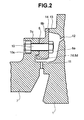
- FIG. 2 Detailed view on the periphery of the spacer 8 is shown in Fig. 2.
- the cooling-air hole 12 for guiding the cooling air onto the turbine first-stage disk 1 is provided opposing to the spacer 8.
- the spacer 8 is jointed to the distant piece 7 through the bolt 10. Since the spacer 8 is a part of the rotary body, for ensuring reliability against axial vibration thereof when being installed, the rotary axis of the spacer 8 is made to be coincident with the rotary axes of the turbine disks 1 and 2, on which the rotor blades 5 and 6 are implanted.
- the faucet or spigot joint is adopted on the attachment surface between the spacer 8 and the distant piece 7.
- the diameter of the spigot joint portion of the spacer 8 of the convex side is a little bit larger than that of the distant piece 7 of the concave side.
- the spacer 8 makes up a cavity 8a for guiding the cooling air to the blades implanted on the turbine first-stage disk 1 with high efficiency.
- a fin 13 is formed on the turbine first-stage disk 1, while being in contact with the spacer 8, thereby forming the cavity 8a between the front surface of the turbine first-stage disk 1 and the rear-side end surface of the spacer 8. Since the spacer 8 is fitted to the distant piece 7 through the bolt joint and the spigot portions 7d and 8d, a seal 14 is provided on the fin 13 having a contact surface with the turbine first-stage disk 1.
- this seal 14 can be used, such as, an "O" ring seal, for an example.
- the cooling air passes through an inner periphery side of the distant piece 7, and it is guided into the cavity 8a from the joint portion 11.
- the cooling air flowing into the cavity 8a is guided to the respective blades of the first-stage rotor blades 5.
- a cooling hole 12 is machined in the turbine first-stage disk 1 in the same number of pieces of the rotary blades of the rotor impeller.
- the pressure within the cavity 8a must be kept at an appropriate value. I f the sealing is bad between the spacer 8 and the turbine first-stage disk 1, a portion of the cooling air leaks therefrom, and then the cooling air comes to be in short for the rotary blades.
- the centrifugal forces act depending upon the mass and the rotary speed thereof. Namely, if the spacer 8 has a complicated shape, a considerable stress acts on a corner or the like of the spacer 8. Then, for avoiding from such the stress concentration, according to the present embodiment, the spacer 8 is attached on the side of the distant piece 7, thereby achieving both the sealing property and ensuring the reliability thereof.
- the spacer 8 is attached on the side of the distant piece 7, thereby achieving both the sealing property and ensuring the reliability thereof.
- the seal member on the turbine first-stage disk 1 also the property can be improved, in particular, in assembling thereof.
- the distant piece and the spacer are made from separate materials, respectively, therefore it is necessary to make an evaluation on the strength in advance, in particular, on the contact stress at the spigot portion and/or on the stress at the bolt hole, in the stage of designing.
- this evaluation on the strength is not necessary if the distant piece and the spacer are made from the same material.
- a special joint is adopted at the connection portion between the distant piece and the rotor, and therefore, from a viewpoint of machining of the joint, the distant piece and the spacer are made from the separate materials.
- the vertical cross-section configuration (in the radius direction thereof) of the spacer 8 is made up, so that the surface opposing to the turbine first-stage disk 1 lies perpendicular to the rotation shaft of the turbine. If making the cross-section configuration of this spacer 8 into a corn-like shape, so that it inclines to a side of the turbine first-stage disk 1, it is not necessary to provide the fin 13 on the turbine first-stage disk 1. However, the spacer 8 is the rotary body, and bending stress applies on the spacer 8 due to the centrifugal forces caused by the spacer 8 per se.
- the distance in the turbine shaft is made short, from the bolt joint portion with the distant piece 7 up to the seal surface by means of the seal member 14.
- the plate thickness of the seal member 8 is made thin, in particular, at the portion 8a projecting into an outer diameter side thereof, where the seal surface is formed, comparing to that of the periphery portion of the seal member 14, which lies in an inner side than this projection portion.
- the spacer used in the present embodiment is a hollow rotary body, and the centrifugal forces applied thereon come to the maximum at the central hole thereof. Accompanying this, the stress at an edge of the screw hole has also importance. Thus, the larger the masses on the outer diameter side, the greater the centrifugal stress applying at the central hole. Then, according to the present embodiment, the plate thickness is made thin on the outer periphery side, thereby achieving reduction of the centrifugal stress applied thereon.
- the turbine first-stagedisk, theturbinesecond-statedisk, thedistantpiece, and the rotor portion of the compressor are stuck on a center of the rotary shaft, however it is also possible to apply the spacer according to the present embodiment, if no such the central hole is formed in the turbine disks.
- An example thereof is shown in Fig. 4.
- This Fig. 4 is the vertical cross-section view of the connection portion between a distant piece 107 and a turbine first-stage disk 101 and a turbine second-stage disk 102, for showing only principle portions thereof.
- the method for attaching the spacer 108 onto the distant piece 107 is same to that shown in the embodiment mentioned above.
- a cavity 108a is formed, and a fin 113 is formed on the turbine first-stage disk 101, contacting on the seal member.
- No such the central hole is formed in the turbine first-stage disk 101, but through holes for stacking bolts 109 are formed at plural positions in the peripheral direction, in a middle portion of the radial direction thereof.
- the bolt positions must be designed appropriately on the basis of the centrifugal stress thereon.
Landscapes
- Engineering & Computer Science (AREA)
- Mechanical Engineering (AREA)
- General Engineering & Computer Science (AREA)
- Turbine Rotor Nozzle Sealing (AREA)
Applications Claiming Priority (2)
| Application Number | Priority Date | Filing Date | Title |
|---|---|---|---|
| JP2002258372A JP2004092609A (ja) | 2002-09-04 | 2002-09-04 | ガスタービン及びそれに用いるスペーサ部材 |
| JP2002258372 | 2002-09-04 |
Publications (2)
| Publication Number | Publication Date |
|---|---|
| EP1396609A2 true EP1396609A2 (fr) | 2004-03-10 |
| EP1396609A3 EP1396609A3 (fr) | 2005-05-04 |
Family
ID=31712297
Family Applications (1)
| Application Number | Title | Priority Date | Filing Date |
|---|---|---|---|
| EP03019480A Withdrawn EP1396609A3 (fr) | 2002-09-04 | 2003-08-28 | Turbine à gaz avec passage de refroidissement délimité par une entretoise et un disque de rotor de turbine |
Country Status (3)
| Country | Link |
|---|---|
| US (1) | US20040040314A1 (fr) |
| EP (1) | EP1396609A3 (fr) |
| JP (1) | JP2004092609A (fr) |
Families Citing this family (3)
| Publication number | Priority date | Publication date | Assignee | Title |
|---|---|---|---|---|
| US20080010127A1 (en) * | 2006-06-09 | 2008-01-10 | Pitney Bowes Incorporated | Intelligent mail system to coordinate direct mail with other marketing channels using mail prediction and mail control |
| US9109450B2 (en) * | 2012-06-14 | 2015-08-18 | United Technologies Corporation | Rotor assembly with interlocking tabs |
| IT202000004585A1 (it) * | 2020-03-04 | 2021-09-04 | Nuovo Pignone Tecnologie Srl | Turbina e pala perfezionate per la protezione della radice dai gas caldi del percorso del flusso. |
Family Cites Families (8)
| Publication number | Priority date | Publication date | Assignee | Title |
|---|---|---|---|---|
| DE744859C (de) * | 1940-09-26 | 1953-02-23 | Bmw Flugmotorenbau Ges M B H M | Einrichtung zur Kuehlung von Abgasturbinen und deren Wellen |
| GB810459A (en) * | 1955-06-14 | 1959-03-18 | Gen Electric | Improved turbomachine rotor with air-cooled blading |
| US2928650A (en) * | 1953-11-20 | 1960-03-15 | Bristol Aero Engines Ltd | Rotor assemblies for gas turbine engines |
| US3572966A (en) * | 1969-01-17 | 1971-03-30 | Westinghouse Electric Corp | Seal plates for root cooled turbine rotor blades |
| US4086757A (en) * | 1976-10-06 | 1978-05-02 | Caterpillar Tractor Co. | Gas turbine cooling system |
| US4438625A (en) * | 1978-10-26 | 1984-03-27 | Rice Ivan G | Reheat gas turbine combined with steam turbine |
| DE3014279A1 (de) * | 1980-04-15 | 1981-10-22 | M.A.N. Maschinenfabrik Augsburg-Nürnberg AG, 4200 Oberhausen | Einrichtung zur kuehlung des inneren einer gasturbine |
| US6185924B1 (en) * | 1997-10-17 | 2001-02-13 | Hitachi, Ltd. | Gas turbine with turbine blade cooling |
-
2002
- 2002-09-04 JP JP2002258372A patent/JP2004092609A/ja active Pending
-
2003
- 2003-08-28 EP EP03019480A patent/EP1396609A3/fr not_active Withdrawn
- 2003-09-04 US US10/653,917 patent/US20040040314A1/en not_active Abandoned
Non-Patent Citations (1)
| Title |
|---|
| None * |
Also Published As
| Publication number | Publication date |
|---|---|
| US20040040314A1 (en) | 2004-03-04 |
| EP1396609A3 (fr) | 2005-05-04 |
| JP2004092609A (ja) | 2004-03-25 |
Similar Documents
| Publication | Publication Date | Title |
|---|---|---|
| US6860110B2 (en) | Gas turbine shaft and heat shield cooling arrangement | |
| JP4582472B2 (ja) | タービンフレーム組立体 | |
| US8191374B2 (en) | Two-shaft gas turbine | |
| US4086757A (en) | Gas turbine cooling system | |
| US6746204B2 (en) | Turbine rotor | |
| US5259727A (en) | Steam turbine and retrofit therefore | |
| JPS6130132B2 (fr) | ||
| AU2020400781B2 (en) | Composite seal structure for a machine, and method of manufacturing the composite seal structure | |
| EP0902163B1 (fr) | Dispositif d'étanchéité entre un boulon de fixation et le trou dans un disque de rotor | |
| EP0921277A1 (fr) | Structure d'etancheite montee entre les disques d'une turbine a gaz | |
| EP2405100A1 (fr) | Agencement d' étanchéité et d'équilibrage combiné pour disque de turbine | |
| EP1079067B1 (fr) | Système d'alimentation en air de refroidissement pour un rotor | |
| US8210823B2 (en) | Method and apparatus for creating seal slots for turbine components | |
| US8062000B2 (en) | Fastening arrangement of a pipe on a circumferential surface | |
| CN100395431C (zh) | 在透平部件的导向叶环和转子叶环之间具有密封件的燃气轮机 | |
| US20040040314A1 (en) | Gas turbine and spacer member for the use therein | |
| EP0911491A1 (fr) | Joint de rotor d'extremite a pression differentielle elevee | |
| JP2000186502A (ja) | ガスタービン | |
| JPS6229701A (ja) | ガスタ−ビン | |
| JP2000274261A (ja) | ガスタービン | |
| JP2007046540A (ja) | タービンのシール構造 | |
| EP3835545A1 (fr) | Rotor de turbine | |
| JPS58214068A (ja) | ラビリンスシ−ル |
Legal Events
| Date | Code | Title | Description |
|---|---|---|---|
| PUAI | Public reference made under article 153(3) epc to a published international application that has entered the european phase |
Free format text: ORIGINAL CODE: 0009012 |
|
| 17P | Request for examination filed |
Effective date: 20030828 |
|
| AK | Designated contracting states |
Kind code of ref document: A2 Designated state(s): AT BE BG CH CY CZ DE DK EE ES FI FR GB GR HU IE IT LI LU MC NL PT RO SE SI SK TR |
|
| AX | Request for extension of the european patent |
Extension state: AL LT LV MK |
|
| PUAL | Search report despatched |
Free format text: ORIGINAL CODE: 0009013 |
|
| AK | Designated contracting states |
Kind code of ref document: A3 Designated state(s): AT BE BG CH CY CZ DE DK EE ES FI FR GB GR HU IE IT LI LU MC NL PT RO SE SI SK TR |
|
| AX | Request for extension of the european patent |
Extension state: AL LT LV MK |
|
| AKX | Designation fees paid |
Designated state(s): DE FR GB SE |
|
| 17Q | First examination report despatched |
Effective date: 20070312 |
|
| STAA | Information on the status of an ep patent application or granted ep patent |
Free format text: STATUS: THE APPLICATION IS DEEMED TO BE WITHDRAWN |
|
| 18D | Application deemed to be withdrawn |
Effective date: 20070724 |