EP1396996A2 - Ajustement de la saturation pour signal RGB - Google Patents
Ajustement de la saturation pour signal RGB Download PDFInfo
- Publication number
- EP1396996A2 EP1396996A2 EP03255429A EP03255429A EP1396996A2 EP 1396996 A2 EP1396996 A2 EP 1396996A2 EP 03255429 A EP03255429 A EP 03255429A EP 03255429 A EP03255429 A EP 03255429A EP 1396996 A2 EP1396996 A2 EP 1396996A2
- Authority
- EP
- European Patent Office
- Prior art keywords
- saturation
- vector
- colour
- colour tone
- rgb
- Prior art date
- Legal status (The legal status is an assumption and is not a legal conclusion. Google has not performed a legal analysis and makes no representation as to the accuracy of the status listed.)
- Withdrawn
Links
Images




Classifications
-
- H—ELECTRICITY
- H04—ELECTRIC COMMUNICATION TECHNIQUE
- H04N—PICTORIAL COMMUNICATION, e.g. TELEVISION
- H04N9/00—Details of colour television systems
- H04N9/64—Circuits for processing colour signals
- H04N9/643—Hue control means, e.g. flesh tone control
-
- H—ELECTRICITY
- H04—ELECTRIC COMMUNICATION TECHNIQUE
- H04N—PICTORIAL COMMUNICATION, e.g. TELEVISION
- H04N1/00—Scanning, transmission or reproduction of documents or the like, e.g. facsimile transmission; Details thereof
- H04N1/46—Colour picture communication systems
- H04N1/56—Processing of colour picture signals
- H04N1/60—Colour correction or control
- H04N1/6002—Corrections within particular colour systems
- H04N1/6005—Corrections within particular colour systems with luminance or chrominance signals, e.g. LC1C2, HSL or YUV
-
- H—ELECTRICITY
- H04—ELECTRIC COMMUNICATION TECHNIQUE
- H04N—PICTORIAL COMMUNICATION, e.g. TELEVISION
- H04N1/00—Scanning, transmission or reproduction of documents or the like, e.g. facsimile transmission; Details thereof
- H04N1/46—Colour picture communication systems
- H04N1/56—Processing of colour picture signals
- H04N1/60—Colour correction or control
- H04N1/6077—Colour balance, e.g. colour cast correction
-
- H—ELECTRICITY
- H04—ELECTRIC COMMUNICATION TECHNIQUE
- H04N—PICTORIAL COMMUNICATION, e.g. TELEVISION
- H04N23/00—Cameras or camera modules comprising electronic image sensors; Control thereof
- H04N23/80—Camera processing pipelines; Components thereof
- H04N23/84—Camera processing pipelines; Components thereof for processing colour signals
- H04N23/86—Camera processing pipelines; Components thereof for processing colour signals for controlling the colour saturation of colour signals, e.g. automatic chroma control circuits
-
- H—ELECTRICITY
- H04—ELECTRIC COMMUNICATION TECHNIQUE
- H04N—PICTORIAL COMMUNICATION, e.g. TELEVISION
- H04N9/00—Details of colour television systems
- H04N9/64—Circuits for processing colour signals
- H04N9/68—Circuits for processing colour signals for controlling the amplitude of colour signals, e.g. automatic chroma control circuits
-
- H—ELECTRICITY
- H04—ELECTRIC COMMUNICATION TECHNIQUE
- H04N—PICTORIAL COMMUNICATION, e.g. TELEVISION
- H04N9/00—Details of colour television systems
- H04N9/77—Circuits for processing the brightness signal and the chrominance signal relative to each other, e.g. adjusting the phase of the brightness signal relative to the colour signal, correcting differential gain or differential phase
Definitions
- the present invention relates a method of adjusting the colour saturation level of a pixel of an RGB format image signal.
- the luminance and chromatic component Y , U, V colour system also known as the luminance and colour difference colour system ( Y , R - Y , B - Y ) is the colour system that is most widely used in video systems.
- the Y , U , and V signals of a video are compressed and transmitted.
- U o and V o now represent colour adjusted chroma signals.
- RGB colour saturation adjustment is performed using the colour saturation adjustment circuit 12 shown in Figure 2.
- Each RGB input sample vector is converted to a YUV sample value, and the colour saturation adjusting method shown in Figure 1 is performed on each YUV sample value.
- the output colour saturation adjusted RGB sample vectors are then obtained by converting the Y 0 ,U 0 ,V colour sample values to RGB colour sample vectors. As can be seen, considerable computation is required for the conversions.
- a method according to the present invention does not involve converting pixel data from RGB to YUV format and is characterised by processing the RGB data C for said pixel to produce at least one value w representing the whiteness of the pixel and three values C T representing the colour tone of the pixel, processing the colour tone representing values by multiplication with a saturation adjustment parameter, regenerating RGB data C o for said pixel from the whiteness representing value or values w and the result of said processing of the colour tone representing values, and outputting the RGB format image signal with the regenerated RGB data for said pixel instead of the original RGB data for said pixel.
- the method is applied to all of the pixels of an image and may also be applied to video, i.e. moving, images.
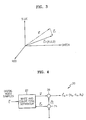
- Figure 3 shows a graphical representation of this decomposition.
- the range of the colour samples is assumed to be 0 ⁇ R, G, B ⁇ 255, however, the invention can be used with colour samples having any range. Note that the direction of the colour tone vector C T is associated with the "hue", while the magnitude of the colour tone vector C T is associated with the "saturation".
- P is a saturation adjustment parameter, which when multiplied against the colour tone vector C T , works to adjust the saturation of the colour tone vector C T .
- the vector P ⁇ C T represents a saturation adjusted colour tone vector C o T .
- the vector C o is a saturation adjusted RGB colour sample vector, which can be output to represent a pixel of an output image.
- the saturation adjustment parameter P can take the form of a colour saturation adjusting gain ⁇ .
- This colour saturation adjusting gain ⁇ can be obtained from the actions of a user of the system or from a circuit constructed to set the colour saturation adjusting gain ⁇ .
- the saturation adjustment parameter P can alternatively include two factors, namely a colour saturation adjusting gain ⁇ and a saturation limiting parameter ⁇ , which are multiplied together.
- the saturation adjustment parameter P can be a variable denoted by r.
- the saturation adjustment parameter P can also take the form of a real colour adjusting gain x.
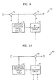
- FIG. 4 shows a block diagram of a circuit 20 for performing the example of the first embodiment of the method for colour saturation adjustment in which the saturation adjustment parameter P takes the form of a colour saturation adjusting gain ⁇ .
- the saturation adjusted RGB colour sample vector C o is obtained from the vector summer 26, which adds the white vector w and the saturation adjusted colour tone vector C o T .
- FIG. 5 shows a block diagram of a circuit 30 for performing the first embodiment of the method in which the decomposition described in equation (3) is performed.
- the white vector calculation circuit 32 calculates a luminance value Y from the RGB colour sample vector C and constructs a white vector w . Each component of the white vector w is equal to the luminance value Y.
- the vector summer 34 subtracts the white vector w from the RGB colour sample vector C to obtain the colour tone vector C T
- the multiplier 36 multiplies the colour tone vector C T by the colour saturation adjusting gain ⁇ to obtain the saturation adjusted colour tone vector C o T .
- the vector summer 38 adds the saturation adjusted colour tone vector C o T and the white vector w to obtain the saturation adjusted RGB colour sample vector C o . It is assumed that the colour saturation adjusting gain ⁇ is equal to or greater than zero.
- the saturation adjusted RGB colour sample vector C o may not be a grey value depending on the choice of the colour tone vector C T or equivalently on the choice of the white vector w .
- the saturation adjusted RGB colour sample vector C o is a grey value.
- P is the saturation adjustment parameter and C o T is a saturation adjusted colour tone vector.
- C o T is a saturation adjusted colour tone vector.
- the second embodiment of the method for colour saturation adjustment is equivalent to the first embodiment except for the fact that additional steps are performed.
- the grey mixing ratio ⁇ g is multiplied with the white vector w before the summation is performed, and the term Y ⁇ (1- ⁇ g ) is included in the summation.
- the term Y ⁇ (1- ⁇ g ) is defined as a grey level adjusted vector.
- the saturation adjusted RGB colour sample vector C o approaches ( Y,Y,Y ) as ⁇ approaches 0. Therefore, the saturation adjusted RGB colour sample vector C o becomes a grey value whose gradation level is Y . Note that the saturation adjusted RGB colour sample vector C o in equation (6b) is equivalent to that in equation (2b) when ⁇ 1.
- FIG. 6 shows a block diagram of a circuit 40 for performing this example of the second embodiment of the method for colour saturation adjustment.
- the minimum value selection circuit 46 obtains the minimum value selected from one and the colour saturation adjusting gain ⁇ , and provides the result as the grey mixing ratio ⁇ g .
- the output signal of the mixer 48 is Y ⁇ (1- ⁇ g )+ w ⁇ g .
- the saturation adjusted RGB colour sample vector C o is obtained from the adder 50, which adds the saturation adjusted colour tone vector C o T and the term Y ⁇ (1- ⁇ g )+ w ⁇ g obtained from the mixer 48.
- Figure 7 shows a block diagram of a particular implementation of the circuit 50 for performing the second embodiment of the method for colour saturation adjustment.
- the circuit 50 implements equation (3) to perform the decomposition.
- the white vector calculation circuit 52 calculates a luminance value Y from the RGB colour sample vector C and constructs a white vector w . Each component of the white vector w is equal to the luminance value Y.
- the vector summer 54 subtracts the white vector w from the RGB colour sample vector C to obtain the colour tone vector C T .
- the multiplier 56 multiplies the colour tone vector C T by the colour saturation adjusting gain ⁇ to obtain the saturation adjusted colour tone vector C o T .
- the minimum value selection circuit 58 chooses a minimum value from one and the colour saturation adjusting gain ⁇ , and provides the result as the grey mixing ratio ⁇ g .
- the output signal of the mixer 60 is Y ⁇ (1- ⁇ g )+ w ⁇ g .
- the saturation adjusted RGB colour sample vector C o is obtained from the adder 62, which adds the saturation adjusted colour tone vector C o T and the term Y ⁇ (1- ⁇ g ) + w ⁇ g that is obtained from the mixer 60.
- an optionally provided feature of the invention is the development of colour saturation limiting functions that can be incorporated into the method for colour saturation adjustment in an RGB colour system.
- Figure 8 shows two multipliers 60 and 62 connected to perform the operation described in equation (9). Accordingly, when using the first embodiment of the method for calculating the saturation adjusted colour tone vector C o T in conjunction with the first embodiment of the method for colour saturation adjustment as expressed in equation (2a), we define the saturation adjustment parameter P as being ⁇ . Similarly, when using the first embodiment of the method for calculating the saturation adjusted colour tone vector C o T in conjunction with the second embodiment of the method for colour saturation adjustment as expressed in equation (6a), we define the saturation adjustment parameter P as being ⁇ .
- the saturation adjustment parameter P is chosen to be the colour saturation adjusting gain ⁇ multiplied by the saturation limiting parameter ⁇ .
- Figure 9 shows a block diagram of a circuit 70 for performing the first embodiment of the method of calculating the saturation adjusted colour tone vector C o T .
- the multiplier 72 multiplies the colour tone vector C T by the colour saturation adjusting gain ⁇ .
- the saturation calculation circuit 74 calculates the saturation level S ( ⁇ C T ) and the ⁇ -selection circuit 76 chooses the value of the saturation limiting parameter ⁇ in accordance with equation (14).
- the saturation adjusted colour tone vector C o T is obtained from the multiplier 78, which multiplies ⁇ and ⁇ C T .
- Figure 10 shows a block diagram of a circuit 80 for performing the second method of calculating the saturation adjusted colour tone vector C o T .
- the saturation calculation circuit 82 calculates the saturation level S ( C T ) and the r -selection circuit 84 chooses the value of r in accordance with equation (16).
- the saturation adjusted colour tone vector C o T is obtained from the multiplier 86, which multiplies r and C T .
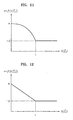
- the mathematical function f ( S ( C T )) can be any function that satisfies the following conditions:
- the saturation adjustment parameter P is the real colour adjusting gain x .
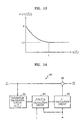
- Figure 14 shows a block diagram of a circuit 90 for performing the third embodiment of the method for calculating the saturation adjusted colour tone vector C o T .
- the saturation calculation circuit 92 calculates the saturation level S ( C T ) .
- the circuit 94 for calculating f ( S ( C T )) evaluates f ( S ( C T )) at the saturation level S ( C T ).
- the real colour adjusting gain circuit 96 chooses the value of x in accordance with equation (18).
- the saturation adjusted colour tone vector C o T is obtained from the multiplier 98, which multiplies x and C T .
- the saturation adjustment parameter P is the real colour adjusting gain x .
- FIG. 15 is a flowchart illustrating the steps used to implement the fourth embodiment of the method for calculating the saturation adjusted colour tone vector C o T in accordance with equations (17) and (20).
- step 1 the colour saturation adjusting gain ⁇ and the colour tone vector C T are acquired.
- step 2 it is determined whether the colour saturation adjusting gain ⁇ is equal to or less than 1. If so, the real colour adjusting gain x is set equal to ⁇ in step 9. If the colour saturation adjusting gain ⁇ is not equal to or less than 1, then in step 3, the saturation level of the colour tone vector C T is determined.
- step 4 it is determined whether the saturation level of the colour tone vector C T is greater than the predetermined limit L.
- step 5 the real colour adjusting gain x is set equal to 1. If the saturation level of the colour tone vector C T is not greater than the predetermined limit L, then in step 6, a first value is obtained by evaluating the mathematical function f at the value of the saturation level of the colour tone vector C T and a second value is obtained by dividing the predetermined limit L by the saturation level of the colour tone vector C T . Additionally in step 6, a minimum value is selected from the first value and the second value and the real colour adjusting gain x is set equal to this minimum value. As can be seen in Figure 15, step 7 can follow either step 9, 5, or 6.
- a saturation adjusted colour tone vector C o T is obtained by multiplying the real colour adjusting gain x with the colour tone vector C T .
- the saturation adjusted colour tone vector C o T can then be used in equation (2a) to perform the first embodiment of the method for colour saturation adjustment, or in equation (6a) to perform the second embodiment.
- Step 8 causes the procedure to loop back to step 1 to obtain the next colour tone vector C T , which may represent another pixel of the same input image, or which may possibly represent the first pixel of a subsequent input image.
- a circuit for performing the fourth embodiment of the method for calculating the saturation adjusted colour tone vector C o T can be constructed similarly to the circuit 90 shown in Figure 14. The difference will be that the real colour adjusting gain circuit 96 will choose the value of x in accordance with equation (20).
Landscapes
- Engineering & Computer Science (AREA)
- Multimedia (AREA)
- Signal Processing (AREA)
- Processing Of Color Television Signals (AREA)
- Color Image Communication Systems (AREA)
- Facsimile Image Signal Circuits (AREA)
Applications Claiming Priority (2)
| Application Number | Priority Date | Filing Date | Title |
|---|---|---|---|
| US10/230,827 US7042521B2 (en) | 2002-08-29 | 2002-08-29 | Method for color saturation adjustment in an RGB color system |
| US230827 | 2002-08-29 |
Publications (2)
| Publication Number | Publication Date |
|---|---|
| EP1396996A2 true EP1396996A2 (fr) | 2004-03-10 |
| EP1396996A3 EP1396996A3 (fr) | 2006-09-13 |
Family
ID=31715267
Family Applications (1)
| Application Number | Title | Priority Date | Filing Date |
|---|---|---|---|
| EP03255429A Withdrawn EP1396996A3 (fr) | 2002-08-29 | 2003-08-29 | Ajustement de la saturation pour signal RGB |
Country Status (4)
| Country | Link |
|---|---|
| US (2) | US7042521B2 (fr) |
| EP (1) | EP1396996A3 (fr) |
| KR (1) | KR100509494B1 (fr) |
| CN (1) | CN1224276C (fr) |
Cited By (3)
| Publication number | Priority date | Publication date | Assignee | Title |
|---|---|---|---|---|
| WO2008080434A1 (fr) * | 2006-12-29 | 2008-07-10 | Robert Bosch Gmbh | Appareil, processus et programme informatique pour limiter la longueur de vecteurs de couleur |
| US7430061B2 (en) * | 2005-01-06 | 2008-09-30 | Toshiba Corporation | System and method to eliminate clipping during color conversion |
| CN102158715A (zh) * | 2010-02-12 | 2011-08-17 | 瑞昱半导体股份有限公司 | 饱和度调整装置及其方法 |
Families Citing this family (20)
| Publication number | Priority date | Publication date | Assignee | Title |
|---|---|---|---|---|
| US7042521B2 (en) * | 2002-08-29 | 2006-05-09 | Samsung Electronics Co., Ltd. | Method for color saturation adjustment in an RGB color system |
| US7355753B2 (en) * | 2003-07-14 | 2008-04-08 | Xerox Corporation | Color saturation adjustment |
| KR20070039032A (ko) * | 2004-07-05 | 2007-04-11 | 코닌클리케 필립스 일렉트로닉스 엔.브이. | 카메라 컬러 잡음 감소 방법 및 회로 |
| KR100691466B1 (ko) * | 2004-09-20 | 2007-03-09 | 삼성전자주식회사 | 영상표시장치에서 색상 및 휘도를 조절하는 방법 및 장치 |
| US7483082B2 (en) * | 2005-04-21 | 2009-01-27 | Kolorific, Inc. | Method and system for automatic color hue and color saturation adjustment of a pixel from a video source |
| TW200643848A (en) * | 2005-06-01 | 2006-12-16 | Wintek Corp | Method and apparatus for four-color data conversion |
| US7746411B1 (en) * | 2005-12-07 | 2010-06-29 | Marvell International Ltd. | Color management unit |
| KR101329140B1 (ko) * | 2007-08-27 | 2013-11-14 | 삼성전자주식회사 | Rgbw 영상 신호의 채도 향상 시스템 및 방법 |
| CN101561991B (zh) * | 2008-04-18 | 2011-06-15 | 群康科技(深圳)有限公司 | 显示装置及其色彩调整方法 |
| CN101729913B (zh) * | 2008-10-14 | 2012-11-28 | 华映视讯(吴江)有限公司 | 影像饱和度的调整方法与系统 |
| CN101742337B (zh) * | 2008-11-17 | 2012-05-23 | 联想(北京)有限公司 | 色彩调节方法和装置 |
| TWI399100B (zh) | 2009-03-06 | 2013-06-11 | 勝華科技股份有限公司 | 影像處理方法 |
| CN101841724B (zh) * | 2009-03-20 | 2011-09-28 | 胜华科技股份有限公司 | 图像处理方法 |
| TWI424751B (zh) * | 2010-08-02 | 2014-01-21 | Realtek Semiconductor Corp | 飽和度調整裝置及其方法 |
| CN102752605A (zh) * | 2011-09-30 | 2012-10-24 | 新奥特(北京)视频技术有限公司 | 一种调整图像/视频色彩饱和度的方法和系统 |
| TWI550593B (zh) * | 2013-08-14 | 2016-09-21 | 友達光電股份有限公司 | 顯示裝置 |
| JP2015154459A (ja) * | 2014-02-19 | 2015-08-24 | 三星ディスプレイ株式會社Samsung Display Co.,Ltd. | 画像処理装置および画像処理方法 |
| US9858845B2 (en) * | 2014-10-22 | 2018-01-02 | Snaptrack, Inc. | Display incorporating dynamic saturation compensating gamut mapping |
| IL273893B2 (en) | 2017-10-09 | 2025-11-01 | Univ Ramot | Modulators of potassium ion and trpv1 channels and uses thereof |
| CN114928730B (zh) * | 2022-06-23 | 2023-08-22 | 湖南国科微电子股份有限公司 | 图像处理方法和图像处理装置 |
Citations (1)
| Publication number | Priority date | Publication date | Assignee | Title |
|---|---|---|---|---|
| US5384601A (en) * | 1992-08-25 | 1995-01-24 | Matsushita Electric Industrial Co., Ltd. | Color adjustment apparatus for automatically changing colors |
Family Cites Families (16)
| Publication number | Priority date | Publication date | Assignee | Title |
|---|---|---|---|---|
| DE3629396C2 (de) * | 1986-08-29 | 1993-12-23 | Agfa Gevaert Ag | Verfahren zur elektronischen Bildverarbeitung |
| DE3629469C2 (de) * | 1986-08-29 | 1994-10-06 | Agfa Gevaert Ag | Verfahren zur Einstellung der Farbsättigung bei der elektronischen Bildverarbeitung |
| US5317678A (en) * | 1989-03-15 | 1994-05-31 | Hitachi, Ltd. | Method for changing color of displayed images by use of color components |
| US5081529A (en) * | 1990-12-18 | 1992-01-14 | Eastman Kodak Company | Color and tone scale calibration system for a printer using electronically-generated input images |
| JP2699711B2 (ja) * | 1991-09-17 | 1998-01-19 | 松下電器産業株式会社 | 階調補正方法および装置 |
| JP3134660B2 (ja) * | 1994-04-14 | 2001-02-13 | 松下電器産業株式会社 | 色変換方法および色変換装置 |
| DE19506595C1 (de) * | 1995-02-24 | 1996-02-01 | Schneider Rundfunkwerke Ag | Verfahren zur Farbtransformation und ein Farbvideosystem |
| US6188788B1 (en) * | 1997-12-09 | 2001-02-13 | Texas Instruments Incorporated | Automatic color saturation control in video decoder using recursive algorithm |
| US20020145610A1 (en) * | 1999-07-16 | 2002-10-10 | Steve Barilovits | Video processing engine overlay filter scaler |
| KR100314097B1 (ko) * | 1999-10-08 | 2001-11-26 | 윤종용 | 백색 신호 성분을 구하고 영상의 밝기를 조절하는 방법 및 장치 |
| JP3634730B2 (ja) * | 2000-09-18 | 2005-03-30 | 三洋電機株式会社 | 色調補正回路および色相補正回路 |
| DE50112268D1 (de) * | 2001-02-09 | 2007-05-10 | Imaging Solutions Ag | Digitale lokale Bildeigenschaftssteuerung mittels Masken |
| US6868179B2 (en) * | 2001-07-06 | 2005-03-15 | Jasc Software, Inc. | Automatic saturation adjustment |
| JP2004054250A (ja) * | 2002-05-29 | 2004-02-19 | Matsushita Electric Ind Co Ltd | 画像表示方法及びその装置 |
| BRPI0302384B1 (pt) * | 2002-07-20 | 2018-06-19 | Samsung Electronics Co., Ltd. | "método para intensificar de forma adaptativa uma cor, e equipamento para intensificar de forma adaptativa a cor de uma imagem" |
| US7042521B2 (en) * | 2002-08-29 | 2006-05-09 | Samsung Electronics Co., Ltd. | Method for color saturation adjustment in an RGB color system |
-
2002
- 2002-08-29 US US10/230,827 patent/US7042521B2/en not_active Expired - Fee Related
-
2003
- 2003-02-28 KR KR10-2003-0012696A patent/KR100509494B1/ko not_active Expired - Fee Related
- 2003-08-29 CN CNB031255647A patent/CN1224276C/zh not_active Expired - Fee Related
- 2003-08-29 EP EP03255429A patent/EP1396996A3/fr not_active Withdrawn
-
2005
- 2005-11-10 US US11/272,158 patent/US7570308B2/en not_active Expired - Fee Related
Patent Citations (1)
| Publication number | Priority date | Publication date | Assignee | Title |
|---|---|---|---|---|
| US5384601A (en) * | 1992-08-25 | 1995-01-24 | Matsushita Electric Industrial Co., Ltd. | Color adjustment apparatus for automatically changing colors |
Cited By (4)
| Publication number | Priority date | Publication date | Assignee | Title |
|---|---|---|---|---|
| US7430061B2 (en) * | 2005-01-06 | 2008-09-30 | Toshiba Corporation | System and method to eliminate clipping during color conversion |
| WO2008080434A1 (fr) * | 2006-12-29 | 2008-07-10 | Robert Bosch Gmbh | Appareil, processus et programme informatique pour limiter la longueur de vecteurs de couleur |
| CN102158715A (zh) * | 2010-02-12 | 2011-08-17 | 瑞昱半导体股份有限公司 | 饱和度调整装置及其方法 |
| CN102158715B (zh) * | 2010-02-12 | 2013-01-30 | 瑞昱半导体股份有限公司 | 饱和度调整装置及其方法 |
Also Published As
| Publication number | Publication date |
|---|---|
| KR20040019847A (ko) | 2004-03-06 |
| US7570308B2 (en) | 2009-08-04 |
| EP1396996A3 (fr) | 2006-09-13 |
| US20040041950A1 (en) | 2004-03-04 |
| US7042521B2 (en) | 2006-05-09 |
| KR100509494B1 (ko) | 2005-08-22 |
| CN1496131A (zh) | 2004-05-12 |
| CN1224276C (zh) | 2005-10-19 |
| US20060061692A1 (en) | 2006-03-23 |
Similar Documents
| Publication | Publication Date | Title |
|---|---|---|
| EP1396996A2 (fr) | Ajustement de la saturation pour signal RGB | |
| EP1017241B1 (fr) | Methode de compensation de couleur d'image lors de l'ajustement du contraste d'une image couleur numérique | |
| EP0971314B1 (fr) | Procédé conservant les détails d'une image digitale dont le contraste est ajusté | |
| US7023580B2 (en) | System and method for digital image tone mapping using an adaptive sigmoidal function based on perceptual preference guidelines | |
| EP0843465B1 (fr) | Appareil et procédé de traitement d'image | |
| US6507372B1 (en) | Image enhancement circuit and method using mean matching/quantized mean matching histogram equalization and color compensation | |
| US5544258A (en) | Automatic tone correction of images using non-linear histogram processing | |
| US5661575A (en) | Gradation correction method and device | |
| EP1377029A2 (fr) | Amélioration des caractéristiques de gradation des images numérique | |
| US7319798B2 (en) | Apparatus generating 3-dimensional image from 2-dimensional image and method thereof | |
| US6167165A (en) | Method for adjusting image detail to compensate for an applied tone scale | |
| EP1111907A2 (fr) | Procédé pour rehausser une image numérique avec réglage de la texture en fonction du bruit | |
| EP1392063A2 (fr) | Dispositif et procédé de réglage de la saturation de couleur | |
| EP1017229B1 (fr) | Procédé de préservation de détails spatiaux et des informations de couleur pendant le réglage d'échelle de tonalité d'une image en couleur numérique | |
| US7652808B2 (en) | Spatially varying luminance compression gamut mapping system and method | |
| US5726682A (en) | Programmable color space conversion unit | |
| EP1021032A2 (fr) | Procédé pour le réglage de l'échelle de tonalité d'une image numérique | |
| US20020136464A1 (en) | Method and circuit arrangement for enhancing the contrast of an image | |
| US4785347A (en) | Method for emphasizing sharpness of a picture image by forming and processing sharp and unsharp signals from a picture image signal | |
| US20070086650A1 (en) | Method and Device for Color Saturation and Sharpness Enhancement | |
| JP2876934B2 (ja) | 画像のコントラスト強調方法及び装置 | |
| EP1017228A2 (fr) | Procédé concervant les détails d'image lors du réglage de l'échelle de tonalités d'une image numérique en couleurs | |
| US6931161B2 (en) | Method for making an exposure adjustment on a rendered image | |
| JPH10173958A (ja) | 映像信号処理装置 | |
| KR101257369B1 (ko) | 디지털 영상 처리 장치에서 선택적인 색상 억압 시스템 |
Legal Events
| Date | Code | Title | Description |
|---|---|---|---|
| PUAI | Public reference made under article 153(3) epc to a published international application that has entered the european phase |
Free format text: ORIGINAL CODE: 0009012 |
|
| AK | Designated contracting states |
Kind code of ref document: A2 Designated state(s): AT BE BG CH CY CZ DE DK EE ES FI FR GB GR HU IE IT LI LU MC NL PT RO SE SI SK TR |
|
| AX | Request for extension of the european patent |
Extension state: AL LT LV MK |
|
| RAP1 | Party data changed (applicant data changed or rights of an application transferred) |
Owner name: SAMSUNG ELECTRONICS CO., LTD. |
|
| RIC1 | Information provided on ipc code assigned before grant |
Ipc: H04N 1/60 20060101ALI20060519BHEP Ipc: H04N 9/68 20060101AFI20060519BHEP |
|
| PUAL | Search report despatched |
Free format text: ORIGINAL CODE: 0009013 |
|
| AK | Designated contracting states |
Kind code of ref document: A3 Designated state(s): AT BE BG CH CY CZ DE DK EE ES FI FR GB GR HU IE IT LI LU MC NL PT RO SE SI SK TR |
|
| AX | Request for extension of the european patent |
Extension state: AL LT LV MK |
|
| AKX | Designation fees paid | ||
| 17P | Request for examination filed |
Effective date: 20070308 |
|
| RBV | Designated contracting states (corrected) |
Designated state(s): DE FR GB NL |
|
| REG | Reference to a national code |
Ref country code: DE Ref legal event code: 8566 |
|
| 17Q | First examination report despatched |
Effective date: 20070903 |
|
| RAP1 | Party data changed (applicant data changed or rights of an application transferred) |
Owner name: SAMSUNG ELECTRONICS CO., LTD. |
|
| STAA | Information on the status of an ep patent application or granted ep patent |
Free format text: STATUS: THE APPLICATION IS DEEMED TO BE WITHDRAWN |
|
| 18D | Application deemed to be withdrawn |
Effective date: 20130709 |